24
TC1044SCP
A
4580D
4580D
ON
ON
ON
ON
ON
ON
ON
ON
.1J63
.1J63
1J63
1J63
503 0D
503 0D
WD 09
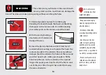
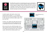
This kit comes with 24" of lead wire.
Cut the wire into six, 2" sections and nine 1" sections.
Strip around 3/32" off both ends of all wires with
.6mm/22gauge stripper.
The 2" sections will attach the in, out and DC jacks
at the top of the PCB and the 1" sections will attach
the breakout board to the bottom center of the PCB.
Insert the stripped ends of the wires into the holes
on the component side of the PCB and solder them on
the back.
9
9
StewMac’s PCB
Holder (#0500)
is perfect for soldering
tiny parts and wires.
With two free hands
and the ability to rotate
the board, you’ll easily
find the perfect angle
to work angle.
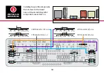
INSTALL 13
LEAD WIRES
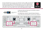
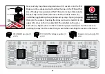
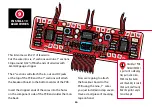
Now we’re going to attach
the breakout board to the
PCB using the nine, 1" wires
you just installed in step seven.
Have a small piece of masking
tape on hand.


