background image


  Stewart Filmscreen 

– Visionary 


CEILING MOUNT   


Professional mounting techniques should be used. Stewart Filmscreen cannot be liable for 
substandard or faulty installations. 

Failure to comply with the instructions and guidance 

contained in this manual may result in voiding the warranty. 


1.  Use a magnetic stud finder, or similar appropriate means, to 

identify the location of solid ceiling joists. If the joists or 

rafters are parallel to the screen case, blocking is required 

between structural elements. 

2.  Mounting hardware must be mounted into solid wood. If no 

joists are available then the ceiling must be blocked.   

3.  Lift the case up to the ceiling and screw the ceiling brackets 

into the joists on both ends of the case (see Figure 3) or 
suspend the case (see Figure 2).  

4.  Ensure that all four mounting holes are being utilized to 

maximize mounting strength.   

5.  For the minimum clearance dimensions for ceiling mount, 

(see Figure 4). 


CAUTION


During installation, do not place the unit on an unstable cart, stand, table or ladder. 

The unit may fall, causing injury to you or others as well as cause possible damage 

to the unit.  

Do not mount to drywall only. There must be wood joists behind the drywall to 

secure the screen. 


Figure 2.

  Visionary unit 

suspended from ceiling    

Figure 3.

  Visionary bottom view 

fastened to ceiling joints 

Summary of Contents for Visionary

Page 1: ...1 Stewart Filmscreen Visionary Retractable Above Ceiling Self Finishing Screen System with Two Piece Construction ...

Page 2: ...ake changes to the product specified in this document Sizes and specifications subject to change without notice at the manufacturer s discretion From time to time this document is updated Current versions of documentation are posted on the Stewart Filmscreen website at www StewartFilmscreen com Revision 1 01 03 Date 04 26 2022 ...

Page 3: ...IMC 12 IMC Wiring Diagram 14 Optional Low Voltage Control LVC 15 Optional Low Voltage Control with IR 16 LVC Wiring Diagram 17 Optional High Voltage Wall Switch HVS 18 Optional Video Interface Control System VICS 19 Installing the Screen Assembly into the Case 20 Operating the Screen 21 Limit Switch Adjustment 22 Caring for and Cleaning the Screen 24 Troubleshooting 25 One 1 Year Limited Warranty ...

Page 4: ...w this manual It will guide you through the installation and the operation of your screen and will also provide you with detailed instructions on how to care for your screen s viewing surface From all of us at Stewart Filmscreen we would like to thank you for choosing Visionary Should you have any questions please don t hesitate to contact our customer service department at 1 310 784 5300 or toll ...

Page 5: ...minal connection must be made as shown in wiring diagrams Proper short circuit and overload protection must be provided at the circuit breaker distribution panel You may use up to a 20 amp maximum circuit breaker with adequate short circuit breaking capacity for your installation USING THIS MANUAL FOR INSTALLATION If you are using this manual to install the Visionary screen you should be aware tha...

Page 6: ...he screen to be installed so that you can plan for the number of people required for installation You will need at least two people to mount a small screen More are needed for larger heavier screens Read everything before you do anything What s inside the box Inside your Visionary unit box you will find everything needed to get started enjoying your Stewart screen Visionary unit preassembled and p...

Page 7: ...r surrounding the screen case Do not remove the wrapping paper surrounding the screen roller You should remove it only after the unit is hung and all electrical connections have been made Removing the screen assembly from the case The unit is shipped with the screen assembly fastened inside Prior to mounting the unit you must remove the screen assembly from the case Using the supplied wrench loose...

Page 8: ...no joists are available then the ceiling must be blocked 3 Lift the case up to the ceiling and screw the ceiling brackets into the joists on both ends of the case see Figure 3 or suspend the case see Figure 2 4 Ensure that all four mounting holes are being utilized to maximize mounting strength 5 For the minimum clearance dimensions for ceiling mount see Figure 4 CAUTION During installation do not...

Page 9: ...Stewart Filmscreen Visionary 9 CEILING MOUNT CONTINUED Figure 4 Ceiling mount detail with minimum clearance ...

Page 10: ... location MOTOR WIRING The Visionary screen system s motor is prewired at the factory No additional motor wiring is required The following pages will outline standard and optional control types for Visionary Connections The following Stewart Filmscreen control options are available for Visionary when placing your order Please refer to the appropriate section to learn more about each control system...

Page 11: ...e 5 Feed the incoming AC Romex or service cord through the Romex connector on the housing Connect the pigtail with wire nuts on the inside of the housing The AC connection to this pigtail should never be made on the outside of the enclosure as this would violate NEC electrical code and UL standards Figure 5 Molex connector unplugged with electrical source ready CAUTION Make sure to finish all wiri...

Page 12: ...k up cable 4 conductor bell wire or cat 5 cable is typically used for long runs o Cat 5 multi conductor unshielded similar type electronic cable can be used to connect the 3 button switch to the LVC The recommended wire gauge is 20 to 24 AWG Use plenum rated cable when required Making the connection 1 Mount the IMC control box near the screen 2 Connect the IMC control box to the screen by connecti...

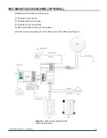
Page 13: ...able with the IMC as options are IR sensor and remote IR wall switch and remote E Node for IP connectivity IBT 100 for RS 232 serial connectivity All of the accessories plug into the CS Bus port of the IMC see Figure 7 Figure 7 IMC wiring diagram from smart accessories ...

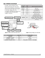
Page 14: ...Neutral NC Pin 3 Motor RED Line NC Pin 4 Motor BLACK Line NC Pin 5 Motor Neutral GREEN NC Connect Ground to Grounding lug on IMC housing Also connect ground wire from motor housing to same lug LVC Contacts IMC 100 COMMANDS COMMON Pin 1 COMMON CHANNEL 1 INPUT Pin 2 UP CHANNEL 2 INPUT Pin 3 DOWN SCREEN TRIGGER INPUT Pin 4 TRIGGER 3 15 VDC w COMMON AC and Motor Fuse Pins 1 2 AC In Pin 1 Pins 3 5 Moto...

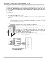
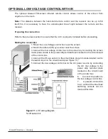
Page 15: ...r long runs o Cat 5 multi conductor unshielded similar type electronic cable can be used to connect the 3 button switch to the LVC The recommended wire gauge is 20 to 24 AWG Use plenum rated cable when required Making the connection 1 Mount the low voltage control box near the screen 2 Connect the low voltage control box to the screen by connecting the screen motor power leads to the power strip t...

Page 16: ... near the screen 2 Mount the infrared IR eye sensor near the screen 3 Connect the low voltage control box to the screen by connecting the screen motor power leads to the power strip terminal block located on the circuit board of the control box 4 Connect the IR eye sensor to the small black plug in module located next to the switch input on the circuit board see Figure 11 5 Connect the low voltage...

Page 17: ...Stewart Filmscreen Visionary 17 LVC WIRING DIAGRAM For ease of readability refer to complete LVC wiring diagram below see Figure 12 Figure 12 LVC complete wiring diagram ...

Page 18: ... The switch alternates directions of screen motion by means of the hot lead using the 3 position switch Preparing the connection Before making the electrical connections you will need An available AC constant power source A 4 conductor Romex or motor connector cable Making the connections 1 Connect the wall switch to the AC constant power source 2 Connect the wall switch to the screen unit s elect...

Page 19: ...ductor 18 ga minimum Romex cable or electrical service cord SJO is advised for this connection Use the supplied wire nuts for connecting the motor leads to this cable 2 Connect a 2 conductor Approx 22 ga wire from the 5 to 12 volt DC trigger output of your projector Use the supplied 3 5 mm phono plugs to terminate the ends of the wire The tip of the plug is positive 3 Next plug in the main AC powe...

Page 20: ...sing the wrench provided secure the screen assembly to the case using bolts inside each end of the screen slot As you tighten the bolts the screen assembly ceiling cover will move forward and lock into place on the case CAUTION During installation of the Visionary screen into the mounted housing be advised that damage can occur to the screen Perform the following actions to avoid damage When lifti...

Page 21: ...shut off to prevent damage from overheating If the motor occasionally needs to be run more than normal i e during initial setup and positioning allow time for the motor to cool down In general when the screen is not in use you should store it in the fully retracted position to protect the screen s surface It is best practice however to deploy the screen for extended periods Periodic deployment on ...

Page 22: ...trol switch to raise the screen up a foot or so before attempting a motor limit switch adjustment If the screen is operated by a screen trigger you must reduce this white limit switch when the screen is stopped in its fully retracted up position Turn the down motor limit switch clockwise to reduce top masking settings Turning the motor limit switch counterclockwise will increase or extend the scre...

Page 23: ...hang freely underneath the screen roller tube The batten bar cannot contact or press against the projection screen roll Make sure to check and correctly adjust the yellow or up limit switch to avoid screen damage from a compacted batten bar Switches are sensitive Go slowly and do quarter turns at all times with the 5 32 hex driver to prevent damage to the motor and to the screen Counterclockwise a...

Page 24: ...in this cleaning kit see Figure 17 For tougher spots you can make a cleaning solution using a water based detergent and warm water To make the solution mix one part Simple Green 409 or other water based industrial cleaner with three parts warm water Moisten a clean cotton cloth or cotton swab with this solution moisten the stained area and gently lift off the stain Never use an aggressive scrubbin...

Page 25: ...hatters when power is activated Can be caused by voltage drop bad connections or a defective switch Have an electrician or qualified service person check all hookups including outboard wiring The unit hums in up mode The screen batten is retracting too far into the case Failure to correct can damage the motor and the screen Do not use the unit until this problem is resolved Have a qualified servic...

Page 26: ... more Heat gain is cumulative and takes time to dissipate If motor use is initiated before it has cooled completely The motor will shut down again when it reaches maximum temperature Dirt fingerprints marks etc on the screen surface Improper handling of screen Lightly brush off or use a mild water based detergent solution with a clean rag or cotton swab Indentions appear on screen surface Debris o...

Page 27: ...enses to and from Stewart are payable by the purchaser Stewart is not responsible for damage in shipment To protect against damage or loss in transit insure the product and prepay all transportation expenses This warranty is in lieu of all other warranties expressed or implied including warranties as to fitness for use or merchantability Any implied warranties of fitness for use or merchantability...

Page 28: ...ww StewartFilmscreen com 1161 W Sepulveda Blvd Torrance CA 90502 USA l 800 762 4999 l Tel 310 784 5300 l Fax 310 326 6870 l Email request stewartfilmscreen com 2022 Stewart Filmscreen Specifications are subject to change without notice ...

Reviews: