


Stewart Filmscreen
– Visionary
14
IMC WIRING DIAGRAM
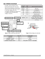
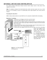
The IMC comes prewired from the
factory to the motor and to the power
cable. For your reference, in the case of
servicing, we broke down the pin layout
for the high voltage side of the
connections (see Figure 9). Always have
a qualified electrician handle high
voltage connections.
AC load
side
IMC
100
Motor Power Connectors
BLACK
Pin 1
AC Line +
WHITE
Pin 2
AC Neutral
NC
Pin 3
Motor RED Line
NC
Pin 4
Motor BLACK Line
NC
Pin 5
Motor Neutral
GREEN
NC
Connect Ground to
“Grounding” lug on IMC
housing. Also connect ground
wire from motor housing to
same lug
LVC Contacts
IMC 100
COMMANDS
COMMON
Pin 1
COMMON
CHANNEL 1 INPUT
Pin 2
UP
CHANNEL 2 INPUT
Pin 3
DOWN
SCREEN TRIGGER INPUT
Pin 4
TRIGGER 3-15 VDC w/ COMMON
AC and Motor Fuse
Pins 1-2
AC In
Pin 1
Pins 3-5 Motor
Connection
LV Contacts
Pin 1
LED
Discovery Button
CS-Bus Downlink
RJ25
CS-Bus Uplink
RJ25
Up
Line
Down
Motor
Common
AC
Pin
1
Neutral
Figure 8.
IMC control board schematic
Figure 9.
High voltage pin schematic


