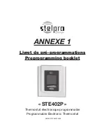
background image

INSSTE402P0711

2

1. Description

The electronic thermostat STE402P can be used to 

control electric heating units such as electric base-

boards, convectors, or aeroconvectors. It keeps the 

temperature of the room at the desired set point with 


WARNING


Before installing and operating this product, 

the owner and/or installer must read, under-

stand and follow these instructions and keep 

them handy for future reference. If these in-

structions are not followed, the warranty will 

be considered null and void and the manu-

facturer deems no further responsibility for 

this product. 

Moreover, the following in-

structions must be adhered to in order to 

avoid personal injuries or property dam-

ages, serious injuries and potentially fa-

tal electric shocks.

 All electric connections 

must be made by 

a qualified electrician

according to 

the electrical and building 

codes

 effective in your region. Do NOT con-

nect this product to a supply source other 

than 120 VAC to 240 VAC, and do not exceed 

the load limits specified. Protect the heating 

system with the appropriate circuit breaker 

or fuse. You must regularly clean dirt accu-

mulations on the thermostat. Do NOT use 

fluid to clean thermostat air vents. 

Note: 

This handling description is printed prior to 

product development. When a part of the product 

specification must be changed to improve operability 

or other functions, priority is given to the product 

specification itself.  In such instances, the instruction 

manual may not entirely match all the functions of 

the actual product.
Therefore, the actual product and packaging, as well as 

the name and illustration, may differ from the manual. 
The screen/LCD display shown as an example in this 

manual may be different from the actual screen/LCD 

display.

a high degree of accuracy. It has an easy user inter-

face and can manage up to four programming periods 

a day. This product is designed for installations with 

electrical current − with a resistive load − ranging from 

1.2 A to 16.7 A at 120/240 VAC.

This thermostat is not compatible with the 

following installations:

•   electrical current higher than 16.7 A with a resistive 

load (4000 W @ 240 VAC and 2000 W @ 120 VAC);

•   electrical current lower than 1.2 A with a resistive 

load (300 W @ 240 VAC and 150 W @ 120 VAC);

•   inductive load (presence of a contactor or a relay); 
•   central heating system.

Parts supplied:

•   one (1) thermostat;
•   two (2) mounting screws; 
•   two (2) solderless connectors suitable for copper wires.

2. Installation

Selection of thermostat location

The thermostat must be mounted on a connection box 

on a wall facing the heating unit, at around 1.5 m (5 

feet) above the floor level, on a section of the wall ex-

empt from pipes or air ducts.

Do not install

 the thermostat in a location where 

temperature measurements could be altered. For 

example:

•   close to a window, on an external wall, or close to a 

door leading outside;

•   exposed  directly  to  the  light  or  heat  of  the  sun,  a 

lamp, a fireplace or any other heat source;

•   close or in front of an air outlet;
•  close to concealed ducts or a chimney; 
•   in a location with poor air flow (e.g. behind a door), or 

with frequent air draft conditions (e.g. head of stairs).

Summary of Contents for STE402P

Page 1: ...INSSTE402P0711 STE402P Programmable electronic thermostat User s guide www stelpro com For further information or to consult this guide online please visit our Web site ...

Page 2: ...l may not entirely match all the functions of the actual product Therefore the actual product and packaging as well as the name and illustration may differ from the manual The screen LCD display shown as an example in this manual may be different from the actual screen LCD display a high degree of accuracy It has an easy user inter face and can manage up to four programming periods a day This prod...

Page 3: ... which means that any wire can be connected to the other Two wire installation Four wire installation 4 Using a screwdriver loosen the screw retaining the mounting base and front part of the thermo stat Remove the front part of the thermostat from the mounting base by tilting it upward 5 Align and secure the mounting base to the con nection box using the two screws supplied 6 Reinstall the front p...

Page 4: ...rature 0 5 degree Tempera ture can be displayed in degrees Celsius or Fahren heit see Display in degrees Celsius Fahrenheit Temperature set point The figures displayed above the icon indicate the temperature set point It can be displayed in degrees Celsius or Fahrenheit see Display in de grees Celsius Fahrenheit ...

Page 5: ... Press and hold down the Mode button 3 Do not press down any button during 1 minute The adjustment of the hour and the day of the week can be done from any of the three modes In case of a power failure the thermostat is self sufficient for 2 hours If the failure lasts less than 2 hours the thermostat saves the adjustment of the hour and the day of the week When the power is restored after an exten...

Page 6: ...nt can change automatically up to 4 times a day The period order is not important From this mode the screen displays the tempera ture the set point the heating power used the hour the day of the week and the current pro grammed period number 1 to 4 displayed on the right hand side of the hour Programming procedure of the Automatic mode 1 To access the Programming mode press down the day of the wee...

Page 7: ...e Then you must press down the Mode button for at least 5 seconds The anticipated start icon will appear or disappear to indicate the activation or the deactivation of the mode This modification will apply to the Auto as well as the Pre Prog mode If you modify the temperature set point manually when these modes are activated the anticipated start of the next period will be cancelled Note Please no...

Page 8: ...xt set point change an ticipated by the preprogramming Note that if the set point is lowered to off the programming will not be effective From this mode the screen displays the tempera ture the heating power used the set point the hour the day of the week and the letter and the current number of the pre programming A0 to Z1 and 0 to 9 displayed on the right hand side of the hour see appendix 1 att...

Page 9: ... exits the View mode At any time it is possible to change the day to be viewed by pressing down the desired day button Fan mode When the thermostat is used to control a heating system equipped with a fan the Fan mode MUST be activated This mode prevents the system to continuously start and stop which could cause fan failure The Fan mode is by default deactivated at the factory The status of this m...

Page 10: ...nd buttons during more than 10 seconds The icon will then disappear indicating that the Security mode is deactivated Temperature control The thermostat controls the temperature of a room with a high degree of accuracy The level of power used to maintain the tempera ture at the set point is expressed as a percentage indicated by the number of bars in the thermome ter displayed The heating power use...

Page 11: ... unit has a switch If so ensure that this switch is turned on The display turns off a few minutes and then turns on again The thermal protection of the heating unit has deactivated the unit due to overheating Ensure that the heating unit is in good condition of operation and that clearance around the appliance is according to the manufacturer s specifications The display has low contrast when heat...

Page 12: ...ty If at any time during this period the unit be comes defective it must be returned to its place of purchase with a copy of the invoice or simply contact our customer service department with a copy of the invoice in hand In order for the warran ty to be valid the unit must have been installed and used according to instruc tions If the installer or the user modifies the unit he will be held respon...

Page 13: ...ANNEXE1STE402P0408 STE402P Thermostat électronique programmable Programmable Electronic Thermostat ANNEXE 1 Livret de pré programmations Preprogramming booklet ...

Page 14: ...ANNEXE1STE402P0408 Pré programmations de base et Pré programmations avancées Standard preprogrammings and advanced preprogrammings ...

Page 15: ...rog Semaine Week Fin de semaine Week end 6am 10pm 8am 12am 2 20 16 20 16 3 22 18 22 18 Horaire commençant à 7h00AM la semaine Week schedule begin at 7h00AM N pre prog Semaine Week Fin de semaine Week end 7am 11pm 7am 11pm 4 20 16 20 16 5 22 18 22 18 N pre prog Semaine Week Fin de semaine Week end 7am 11pm 9am 1am 6 20 16 20 16 7 22 18 22 18 Horaire commençant à 8h00AM la semaine Week schedule begi...

Page 16: ...maine Week Fin de Semaine Week End 7am 1am 8am 2am C8 18 14 18 14 C9 19 15 19 15 D0 20 16 20 16 D1 21 17 21 17 D2 22 18 22 18 D3 23 19 23 19 D4 24 20 24 20 N pre prog Semaine Week Fin de Semaine Week End 7am 1am 9am 3am D5 18 14 18 14 D6 19 15 19 15 D7 20 16 20 16 D8 21 17 21 17 D9 22 18 22 18 E0 23 19 23 19 E1 24 20 24 20 Horaire commençant à 7h00AM la semaine Week schedule beginning at 7h00AM N ...

Page 17: ...ne Week Fin de Semaine Week End 7am 12am 8am 1am J1 18 14 18 14 J2 19 15 19 15 J3 20 16 20 16 J4 21 17 21 17 J5 22 18 22 18 J6 23 19 23 19 J7 24 20 24 20 N pre prog Semaine Week Fin de Semaine Week End 7am 12am 9am 2am J8 18 14 18 14 J9 19 15 19 15 K0 20 16 20 16 K1 21 17 21 17 K2 22 18 22 18 K3 23 19 23 19 K4 24 20 24 20 Horaire commençant à 7h00AM la semaine Week schedule beginning at 7h00AM N p...

Page 18: ...aine Week Fin de Semaine Week End 7am 11pm 8am 12am P4 18 14 18 14 P5 19 15 19 15 P6 20 16 20 16 P7 21 17 21 17 P8 22 18 22 18 P9 23 19 23 19 Q0 24 20 24 20 N pre prog Semaine Week Fin de Semaine Week End 7am 11pm 9am 1am Q1 18 14 18 14 Q2 19 15 19 15 Q3 20 16 20 16 Q4 21 17 21 17 Q5 22 18 22 18 Q6 23 19 23 19 Q7 24 20 24 20 Horaire commençant à 7h00AM la semaine Week schedule beginning at 7h00AM ...

Page 19: ...eek Fin de Semaine Week End 7am 10pm 8am 12am V7 18 14 18 14 V8 19 15 19 15 V9 20 16 20 16 W0 21 17 21 17 W1 22 18 22 18 W2 23 19 23 19 W3 24 20 24 20 N pre prog Semaine Week Fin de Semaine Week End 7am 10pm 9am 1am W4 18 14 18 14 W5 19 15 19 15 W6 20 16 20 16 W7 21 17 21 17 W8 22 18 22 18 W9 23 19 23 19 X0 24 20 24 20 Horaire commençant à 7h00AM la semaine Week schedule beginning at 7h00AM N pre ...

Page 20: ...anada Téléphone 1 866 628 5776 Sans frais Télécopieur 450 441 1969 Courriel contact stelpro com Site Web www stelpro com Customer service Stelpro Design Inc 1041 Parent Street St Bruno Quebec J3V 6L7 Canada Tel 1 866 628 5776 toll free Fax 450 441 1969 Email contact stelpro com Web site www stelpro com ...

Reviews: