ENO
CILI
S
R
A
E L
C
. Z
O . L
F 2 /
1 t e
N
0 2 5
1 3 .
o N
m
e t I
. A .
S . U
N I E
D
A
M
NOTE:
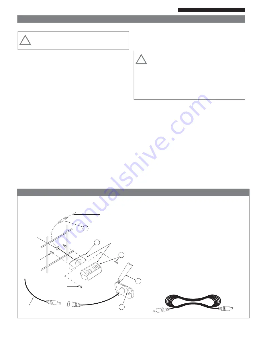
Location of the sensor is as follows:
a) Single tier seating - 6 feet above floor.
b) Double tier seating - 7 feet above floor.
No. 8 Plastic
anchors
5/8” Hole
Cable to
Steam Generator
Temperature
Sensor and Housing
(Shipped Assembled)
No. 8 Screws
1” Long
2
3
4
5
STEPS TO INSTALL SENSOR:
1) Take new sensor assembly and connect to 50’
sensor cable. Please observe polarity of the 50’ cable.
Make sure the male end of the cable is routed toward
the sensor in the steam room.
2) Peel off adhesive backing from sensor.
3) Carefully apply silicone sealant around rear edge.
4) Feed wires back into wall and press sensor firmly to
wall (be careful to align plate holes with anchor holes).
5) Install screws, and snap chrome cover back into
place.
6) Temperature sensor assembly must form a 100%
water tight seal to the wall using silicone supplied.
1
50 Foot Sensor Cable
Male end
50’ sensor cable
Male end
05/13
Pub. No. 601-C
- 8 -
Figure 5 - Sensor Installation - Inside Steamroom
Owners Manual
Digital Command Center Installation
Models: HC-9 thru HC-24 with DCCP Control
VI. Digital Command Center Installation:
WARNING:
All the electrical power to the steam
generator MUST be turned OFF before proceeding with
installation.
A) The DCCP comes factory wired for either one or two
steam rooms. The following installation instructions are
typical for both room installations. The configuration for
one or two room is set at the factory. When the generator
is configured for two rooms (SRP-Second Room Package
must be ordered) it will have 2 room temperature sensors
(one per room), two electric steam valves, two USER
BYPASS CONTROLs, and two steam heads. The electric
steam valves will be labeled 1 and 2. The connections for
the sensors, USER BYPASS CONTROL(s), and aroma
pumps, will all be labeled for room 1 and room 2. It is very
important to pay attention not get the connection to room
1 and room 2 crossed. If the generator is configured for
one room there will not be any special markings.
B) USER BYPASS CONTROL(s): The USER BYPASS
CONTROL should be located outside the steam room
door convenient to the bather. This control gives the
bather limited control of the steam room. The system will
operate without this control but this function is lost. See
the operating instructions for further information on this
function. Route the USER BYPASS CONTROL wire from
the selected mounting area to the control board in the
steam generator (see Figue 6 and 7). The USER
BYPASS CONTROL mounts to 2-1/8” or 55 mm round
hole in the wall.
C) DIGITAL COMMAND CENTER is intended to be used
solely by the manager. It should be located at a conve-
nient height for programming. It may be mounted on the
wall of the utility room near the steam generator, in the
manager’s office, or the front desk. The factory supplied
wire is 50 feet long, therefore the generator must be
located within its reach.
IMPORTANT:
The digital command center is unique
and not to be confused with the USER BYPASS
CONTROL wires or the sensor wires. The Digital
Command Center uses a 4 wire connector, the USER
BYPASS CONTROL uses a 6 wire connector and the
room sensor uses a 2 wire connector. Route the Digital
Commander Center wire from the selected mounting
location to the control board located in the steam
generator (see Figure 6 and 7). The Digital Command
Center mounts to a hole in the wall 2-1/2”w x 7-7/8”h.
D) Room Temperature Sensor(s): The room temperature
sensor is required for operation. The sensor must be
located in the steam room approximately six feet above
the floor and never closer than one foot to the ceiling or
the corner of the room. Route the cable from this location
to the control module on the steam generator. The sensor
mounts to a 5/8” hole in the wall (see Figure 5 for more
detail).
!
!


