STC TECHNOLOGY Co.,Ltd.
STC12C5A08/16/32/60
8-bit micro-controller
This document contains information on a new product under development by STC.STC reserves the right to change or discontinue this
product without notice. 2007/12 version A1
Serial Peripheral Interface(SPI)
The device provides another high-speed serial communication interface, the SPI interface. The SPI is a
full-duplex, high-speed, synchronous communication bus with two operation modes:
Master
mode and
Slave
mode. Up to 3Mbit/s can be supported in either
Master
or
Slave
mode under the Fosc=12MHz.
Two status flags are provided to signal the transfer completion and write-collision occurrence.
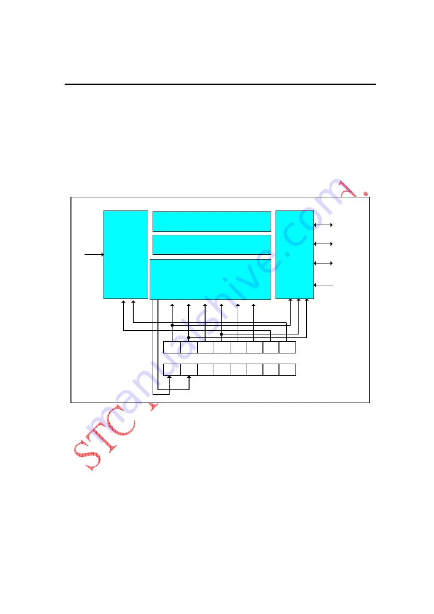
There are three pins implementing the SPI functionality, one of them is SCLK(P1.7), next is MISO(P1.6),
the other is MOSI(P1.5). An extra pin SS(P1.4) is designed to configure the SPI to run under
Master
or
Slave
mode. Data flows from master to slave via MOSI(Master Out Slave In) pin and flows from slave to
master via MISO(Master In Slave Out) pin. The SCLK plays as an output pin when the device works
under
Master
mode, while as an input pin when the device works under
Slave
mode. If the SPI system is
disabled, i.e.
SPEN
(
SPCTL
.6)=0, these pins are configured as general-purposed I/O port(P1.4 ~ P1.7).
Two devices with SPI interface communicate with each other via one synchronous clock signal , one
input data signal, and one output data signal. There are two concerns the user could take care, one of
them is latching data on the negative edge or positive edge of the clock signal which named
polarity
, the
SPICTL
SPR0
SPR1
CPHA
CPOL
MSTR
DORD
SPEN
SSIG
SPI Control
Shift In Register
Shift Out Register
Clock Divider
I/O control
SPISTAT
-
-
-
-
-
-
WCOL
SPIF
P1.6
(MISO)
P1.5
(MOSI)
P1.7
(SPICLK)
P1.4
(SS)
4,
16,
64
128
Fosc
SPI block diagram
http://www.DataSheet4U.net/
datasheet pdf - http://www.DataSheet4U.net/


