background image

8 / 48 

13

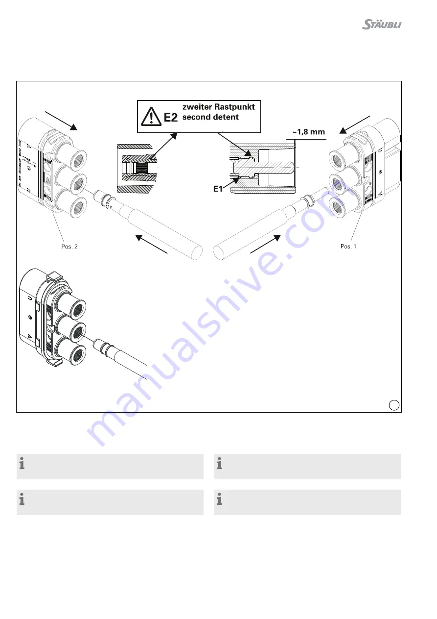
Montage in die Kontaktträger

Assembly in insulator

(ill. 13)

Leitung mit angecrimptem Kontakt von Hand hinten in die Isola-

tion stossen bis zum spürbaren Einrasten am zweiten Rastpunkt 

(E2) (siehe Kontrollmaß)�

(ill. 13)

By hand press cable with crimped-on contact part into the insu-

lation from the back until it perceptibly engages into place to the 

second detent (E2) (see control dimension)�


Hinweis:


Die mittlere Kontaktkammer ist für den PE-Kontakt und daher 

die Buchsenseite “voreilend” ausgeführt�


Note:


The middle contact chamber is intended for the PE, therefore 

mating first and breaking last on the socket side�


Hinweis:


Leere Kontaktkammern (ohne Stift bzw� Buchse) müssen mit 

Blindstopfen verschlossen werden�


Note:


Unpopulated contact chambers have to be sealed with blind 

plugs�

OK

RobiFix-FZEM Vorderteil

RobiFix-FZEM front part

Summary of Contents for RobiFix

Page 1: ...keinbaudose RobiFix B ID 37 Schweißkoffer Umformerschrankeinbau 38 Sonderfall Einbau am Roboterfuß J1 44 Montage von doppelten Schlauchpaketen an Schweißtransformator 46 47 Modification history 48 Content Product overview 2 Safety Instructions 3 4 Tools required 4 Cable preparation 6 Crimping 7 Assembly in insulator 8 Fitting Removing the blind plugs 9 Mounting the cable strain relief 10 Mounting ...

Page 2: ...g Cable strain relief 2 4 RobiFix SS RobiFix Schulterschrauben M5 RobiFix shoulder screws M5 4 5 KM SHR M5x25 Montageschrauben für Pos 3 Mounting screws for Pos 3 4 6 Leiter 25 mm2 50 mm2 Cable 25 mm2 50 mm2 7 Buchse BP8 Socket BP8 3 8 Stift SP8 Pin SP8 3 9 6 kant Mutter M5 Hexagonal nut M5 4 PRODUKTÜBERSICHT PRODUCT OVERVIEW Bisherige Ausführung 2020 09 Previous version 2020 09 Aktuelle Ausführun...

Page 3: ... note that all certifications are voided when such a plug combination is used Stäubli Electrical Connectors Stäubli lehnt jegliche Haftung infol ge Nichteinhaltung dieser Warnhinweise ab Stäubli Electrical Connectors Stäubli does not accept any liability in the event of failure to observe these warnings IEC 60417 6182 Installation elektrotechnisches Fachwissen Installation electrotechnical experti...

Page 4: ... in verschmutztem Zustand miteinander gesteckt werden Unmated plug connectors must be protected from moisture and dirt The male and female parts must not be plugged together when soiled Nützlicher Hinweis oder Tipp Useful hint or tip Weitere technische Daten entnehmen Sie bitte dem Produktkata log www staubli com electrical For further technical data please see the product catalog www staubli com ...

Page 5: ... System CAS MTB11 25 50 18 3023 Crimpeinsatz Crimping die 25 mm 4 AWG MTB13 35 50 18 3024 Crimpeinsatz Crimping die 35 mm 2 AWG ALG2 110 18 3043 Akkuladegerät Battery charger 110 120 V AC Hinweis Bedienungsanleitung MA306 www staubli com electrical Note Operating instructions MA306 www staubli com electrical ill 5 ill 4 Crimpzange ill 4 Crimping pliers Hinweis Bedienungsanleitung MA224 www staubli...

Page 6: ...luded in delivery with sleeve expander ill A page 5 over the outer jacket 4 ill 10 einschalig doppelt single double Ø 10 4 10 9 RobiFix RR10 15 A 30 4167 3 Stück pieces 30 4192 100 Stück pieces 5 ill 11 einschalig single Ø 7 5 10 3 Schrumpfschlauch mit Innenkleber S Adhesive lined form shroud S Ø 7 5 mm 9 7 mm DERAY IAKT 3 1 19 0 6 0 mm Ø 8 5 mm 10 3 mm DERAY IAKT 3 1 12 0 4 0 mm Nicht im Lieferum...

Page 7: ...yp 2 zum Einsatz kommen Important The PE cable must be marked in the connection zone with a green yellow shrink on sleeve over the black outer sheath Alternatively a PE cable with a green yellow outer sheath e g type 2 can be used Crimpen Crimping ill 12 Leitung in die Crimphülse einführen und während dem Crimpen festhalten ill 12 Insert cable into the crimping sleeve During the crimping operation...

Page 8: ...perceptibly engages into place to the second detent E2 see control dimension Hinweis Die mittlere Kontaktkammer ist für den PE Kontakt und daher die Buchsenseite voreilend ausgeführt Note The middle contact chamber is intended for the PE therefore mating first and breaking last on the socket side Hinweis Leere Kontaktkammern ohne Stift bzw Buchse müssen mit Blindstopfen verschlossen werden Note Un...

Page 9: ...weise im Batterie oder E Mobility Bereich Note Only needed in special circumstances i e 2 times 2 phases and 1 ground contact chamber would be left empty or in ground free applications as in battery or e mobility Demontage der Blindstopfen Removing the blind plugs ill 15 Ausbauwerkzeug MBA WZ5 Bestell Nr 18 3014 ill 15 Extraction tool MBA WZ5 Order No 18 3014 Blindstopfen von Hand bis zum 2 Einras...

Page 10: ... on one side with a coding tongue K to fit in the corresponding cut out F of the insulation ill 17 Die zweite Hälfte mit 2 Kodierzungen K der Kabelzugentlastung von der gegenüberliegenden Seite über die Leitungen legen und beide Hälften bis zum spürbaren Einrasten zusammenpressen Die 2 Schrauben und Muttern zusammenschrauben und mit zusammenschrauben und mit einem Drehmomentschlüssel anziehen Anzu...

Page 11: ...used without the strain relief screwed in place Kabelabfangung Cable clamping ill 22 Zur Vermeidung von Beschädigun gen am Zuleitungskabel des RobiFix ist eine zusätzliche Kabelabfangung erforderlich Die Kabelabfangung muss entsprechend den Gegebenheiten des Einbauraums erfolgen und ist nicht im Stäubli Lieferumfang enthalten Ill 22 zeigt nur eine schematische Darstellung ill 22 To avoid damage to...

Page 12: ...5 RobiFix LOCK ohne beigelegte Schrauben von Hand auf den gesteckten RobiFix aufstecken ill 25 Mount RobiFix LOCK without enclosed screws by hand onto the connected RobiFix ill 26 Danach Klettband einfädeln und zusätzlich sichern ill 26 Then attach the hook and loop fasteners strip for additional safety Demontage Klettband lösen und RobiFix vom RobiFix LOCK trennen Disassembly Detach the hook and ...

Page 13: ...sichern Then clip the second RobiFix connector pair into RobiFix TwinLock and secure with both cable ties C Variante C Robotermontage Option C Robot mounting ill 28 Befestigungslöcher gemäß Bohrplan bohren ill 27 Drill mounting holes according to drilling plan ill 29 RobiFix LOCK mit den 2 Schrauben auf den Untergrund schrauben RobiFix aufstecken ill 29 Mount RobiFix LOCK with both screws onto a f...

Page 14: ... ill 31 Clip RobiFix TwinPower B into the first RobiFix connector pair ill 32 Dann das zweite RobiFix Steckerpaar in den RobiFix TwinPower B oben einstecken und mit zwei Kabelbinder C sichern ill 32 Then clip the second RobiFix connector pair into RobiFix TwinPower B and secure with both cable ties C ill 33 Die Kabelbinder C werden jeweils durch die am Einzelteil RobiFix TwinPower A angebrachte Nu...

Page 15: ...T TS150 30 0021 ist separat zu bestellen order separately RobiFix B ZEM mit FD50 RobiFix B ZEM with FD50 ill 35 Geeignet für Kabel Außen Ø 27 mm 35 mm Dichtungsdurchführung FD50 mit Schraubendreher an der Ablösrille einstechen ill 35 Suitable for cable of outside Ø 27 mm 35 mm Insert screwdriver in release groove of seal FD50 ill 36 und Verschlussdeckel herausziehen Bei Kabeldurchmesser kleiner al...

Page 16: ...d Kontaktträger RobiFix Zugentlastungs schelle Z auf Kabelmantel befestigen Es ist darauf zu achten dass die Schrauben abwechselnd fest gedreht werden Anzugsdrehmoment 1 N m ill 39 After inserting the seal and contact carrier attach the RobiFix strain relief Z on the cable jacket Take care to tighten the screws alter nately tightening torque 1 N m Hinweis Richtige Montage der FD50 Dichtung kontrol...

Page 17: ...RobiFix B ZEM with WST TS150 ill 42 Wärmeformschrumpfschlauch in die vorgesehene Montagenut M positio nieren Danach gleichmäßig auf Leitung und in Montagenut aufschrumpfen Dichtungsdurchführung FD50 ist über flüssig ill 42 Position heat shrink tube over the groove M Then shrink evenly onto the cable and into the locating groove Seal FD50 is unnecessary Hinweis Weitere Hinweise für die Verarbei tun...

Page 18: ...oad ill 46 Die zusammengesteckten Steckverbin der an die Montagefläche positionieren und M5 Zylinderschrauben mit Drehmo mentschlüssel anziehen Anzugsdrehmoment 3 N m ill 46 Position the mated connectors on the mounting surface and screw up the M5 screws with a torque wrench tightening torque 3 N m Hinweis Die Befestigungsschrauben im Be reich der Kabelzugentlastung dienen zur mechanischen Abstütz...

Page 19: ...ocket contact carrier RobiFix B FZEM mit Kabelverschraubung M40 RobiFix B FZEM with cable gland M40 ill 47 M40x105 Klemmbereich Ø 18 mm bis Ø 35 mm Schlüsselweite 53 mm Drehmomentschlüssel Bestell Nr 18 3050 und Einsatz SW53 Bestell Nr 18 3051 Drehmomente Hutmutter 17 N m Gewindeeinsatz zum RobiFix FZEM Gehäuse 20 N m ill 47 M40x105 Clamping range Ø 18 mm up to Ø 35 mm Width across flats 53 mm Tor...

Page 20: ...ce to the second detent E2 see control dimension ill 13 page 8 ill 49 Vorderteil und Rückteil bis zum spürbaren Verrasten zusam menschieben A Nach dem Einrasten Kabelverschraubung mit Gabelschlüssel SW53 18 0350 18 0351 anziehen ill 49 Push the front and back parts together until they engage A After locking tighten cable gland with an open end wrench 53 mm 18 0350 18 0351 Wichtig Manche Leitungen ...

Page 21: ...eren und mit Heißluftgebläse 2500 W schrumpfen ill 50 Pull on the WST TS150 and FZEM housing back shell over the cable Crimp the sockets BP8 xx on each conductor ill 11 page 7 By hand press cable with crimped on contact part into the insulation from the back until it perceptibly engages into place to the second detent E2 see control dimension ill 13 page 8 Push the front and back parts together un...

Page 22: ...lso re move the cable strain relief ill 52 Den vormontierten Stiftkontaktträger RobiFix S mit leichtem Druck in die dafür vorgesehenen Positionierstege P drücken ill 52 Gently press the pre assembled pin contact carrier RobiFix S into the positioning studs P ill 53 Nach dem Fixieren des Kontaktträgers den Deckel schräg einfä deln und Schrauben mit Drehmomentschlüssel anziehen Anzugsdrehmoment 5 N ...

Page 23: ... torque wrench Tightening torque 3 N m Flanschmontage Flange mounting RobiFix B FZEM A und RobiFix S FZEE B mit Flanschplatte ill 54 A Zuleitung am Roboter Achse 1 B im Roboter Achse 1 RobiFix B FZEM A and RobiFix S FZEE B with flange plate ill 54 A supply lead on robot Joint 1 B in robot Joint 1 Bohrplan Flanschplatte Drilling plan for flange plate Flanschplatte gemäß Bohrplan fertigen Make flang...

Page 24: ...g single conductors for power supply ill 58 Kabelzugentlastung RobiFix FEJ1 in korrekter Position auf die untere Befestigungsklammer aufsetzen Kodierung K beachten und mit den Befestigungsschrauben S M5x28 2x mit 5 N m anziehen ill 58 Position RobiFix FEJ1 properly onto the mating clamp underneath observe coding K and tighten both M5x28 screws S with 5 N m torque Die Positionszapfen P erleichtern ...

Page 25: ... sind für RobiFix S FZEE Stiftseite auf Roboterseite ill 59 Drilling plan and dimensions for RobiFix FEJ1 Dimensions with correspond to the RobiFix S FZEE male connector on robot side Befestigungsschrauben M5x20 mit 3 N m anziehen Tighten the M5x20 mounting screws to 3 N m Flanschbefestigung RobiFix B FEJ1 angeschraubt RobiFix B FEJ1 flanged strain relief screwed on ...

Page 26: ... dresspack are to be plugged to jack eted cable transformer connection Transformatorseite Transformer side RobiFix S ZEM Roboterseite Robot side RobiFix B MTB Montage RobiFix S ZEM Assembly RobiFix S ZEM Montageablauf identisch mit RobiFix B ZEM siehe Seite 15 Wobei anstatt RobiFix B MTB RobiFix S MTB mit Stiftkontak ten montiert wird Assembly procedure identical with RobiFix B ZEM see page 15 Exc...

Page 27: ... FZEE ist identisch mit Montage vom RobiFix S FZEE auf Seite 21 Anstelle von Stiftkontraktträger RobiFix S wird der Buchsenkon taktträger RobiFix B mit Buchsenkontakten in das RobiFix FZEE Gehäuse montiert Assembly of RobiFix B FZEE is identical with assembly of RobiFix S FZEE 30 4039 on page 21 Instead of pin contact carrier RobiFix S the socket contact carrier RobiFix B with socket contacts is m...

Page 28: ...svariante k kurz Stiftkontakte 41 mm Connection version k short Pin contacts 41 mm ill 63 Bei der Verwendung der Anschlussstecker S8 M8 41 Ag Ver gussmasse und Gewindebuchsen vorbereiten ill 63 When using connection plug S8 M8 41 Ag prepare casting com pound and threaded sockets Montage TAE1 und Anschlussstecker am Transformator Mounting of TAE1 and connecting plug on the transformer ill 64 Stiftk...

Page 29: ...erwendung des Stiftkontaktes S8 M8 57 Ag Verguss masse und Gewindebuchsen M8 Gewindebuchsen vorbereiten ill 65 When using the pin contact S8 M8 57 Ag prepare casting com pound and threaded sockets M8 primary terminals Anschlussvariante k kurz und Anschlussvariante l lang mit Kodierung TAE1 C Connection version k short and connection version l long with coding key TAE1 C ...

Page 30: ... TAE1 Bestell Nr 30 4133 5 Kombi Schraube K11 SHR M5x20 ISO 4762 DIN912 Bestell Nr 15 5302 4x bereits vormontiert 6 Buchse B8 M8 AG Bestell Nr 30 4160 3x bereits vormontiert ill 67 1 RobiFix transformer angled adapter casing RobiFix TWA G Order No 30 4121 2 Complete angled adapter holding frame supplied loose RobiFix TWA D K Order No 30 4119 3 S8 M8 71 pin contacts preassembled Order No 33002101 3...

Page 31: ...mator Anschlussteckerber binder RobiFix TAE1 aufstecken Kodierung beachten 4 Kombi Schrauben M5x20 mit 3 N m anziehen ill 69 The S8 M8 71 pin contacts are screwed into the B8 M8 sockets to a tightness of 5 N m preassembled Fit the preassembled TWA right angled adapter onto the RobiFix TAE1 transformer terminal connector verify the orienta tion of the coding slot Tighten the 4 M5x20 screws to 3 N m...

Page 32: ...ind um die Phasen U und V nicht zu vertauschen Note Make sure the orientation of the coding slot is the same for the insulator on the transformer as for the insulator on the RobiFix TWA in order not to mix up the phases U and V Halterahmen auf das Gummiteil RobiFix TAE1 anbringen mit den 4 Schrauben an das Gehäuse festschrauben und mit 2 N m anziehen Fit the holding frame to the RobiFix TAE1 rubbe...

Page 33: ...hten Note Additional cable clamping is essential Not included in delivery Guidelines of the end user must be observed RobiFix Transformator Winkeladapter RobiFix transformer Angled adapter RobiFix TWA Kabelabfangung Cable clamping Kabelzugentlastung Cable strain relief Anbaumöglichkeiten an den RobiFix Transformator Einzeladern Options for fitting to RobiFix transformer Single conductors Transform...

Page 34: ...biFix transformer Angled adapter RobiFix TWA Kabelzugentlastung Nicht im Stäubli Lieferumfang Cable strain relief Not included in Stäubli delivery Hinweis Eine zusätzliche Kabelabfangung ist zwingend erforderlich sie ist nicht im Lieferumfang enthalten Montagevorschriften des Automobilherstellers sind zu beachten Note Additional cable clamping is essential Not included in delivery The assembly ins...

Page 35: ...rews to 3 N m Then before plugging on RobiFix B FZEM check that con tacts are free from dirt and cleanse the contact area with a clean lint free cloth if necessary ill 74 Den konfektionierten Stecker RobiFix B FZEM bis zum Anschlag auf die mit RobiFix TAE1 ausgestatte te stationäre Roboter Schweißzange stecken Schrauben mit Drehmomentschlüssel 3 N m anziehen ill 74 Plug ready assembled RobiFix B F...

Page 36: ... free cloth if necessary ill 76 Konfektionierter Stecker RobiFix B ZEM bis zum Anschlag auf die mit RobiFix TAE1 ausgestatte te stationäre Roboter Schweißzange stecken Schrauben mit Drehmomentschlüssel 3 N m anziehen ill 76 Plug ready assembled RobiFix B ZEM into the stationary robot welding gun equipped with RobiFix TAE1 as far as it will go Tighten screws to 3 N m with torque wrench Achtung Nich...

Page 37: ...binets i e energy flow from the inside to the outside or socket side inside and pin side outside Für Sonderfälle kann das Produkt auch am Roboterfuß genutzt werden Da der Energiefluss von außen nach innen geht bzw Buchsenseite außen und Stiftseite innen liegt wird die Montage in gedrehter Form von innen nach außen notwendig Darstellung auf Seiten 43 44 For special cases the product can also be use...

Page 38: ...ld timer cabinet for the RobiFix B ID receptacle Cut out must be clean and free of burrs Schaltschrankanschluss mit montiertem Buchsen teil RobiFix B MTB Cabinet connection with fitted RobiFix B MTB Vorbereitung des RobiFix B MTB bei Außenkontaktierung mit RobiFix S MTB Preparing the RobiFix B MTB for exterior connection with RobiFix S MTB ill 79 Schaltschrankeinbau mit montierten Buchsenteil Robi...

Page 39: ...ung ill 82 Previous version ill 83 Aktuelle Ausführung ill 83 Current version ill 84 85 Die Schrauben um 180 drehen und auf der Unterseite des RobiFix B MTB einstecken ill 84 85 Turn the screws by 180 and insert them on the bottom side of the RobiFix B MTB ill 84 Bisherige Ausführung ill 84 Previous version ill 85 Aktuelle Ausführung ill 85 Current version ...

Page 40: ...Die Zuleitung mit Einzeladern wird mit Hilfe von RobiFix S MTB angeschlos sen RobiFix B MTB ill 86 Assembled RobiFix B ID receptacle The welding power supply with single conductors is connected using the RobiFix S MTB RobiFix B MTB Schaltschrank Außenseite Weld timer cabinet exterior Steckrichtung Plug in direction Schaltschrank Innenseite Weld timer cabinet interior Steckrichtung Plug in directio...

Page 41: ...a plate thickness of 4 5 mm M5 nuts must be used in addition for a plate thickness of 4 mm Anordnungsreihenfolge der Befestigungselemente 4 x in RobiFix B ID bereits vormontiert Arranging the fitting elements in the correct order 4 elements already preassembled in the RobiFix B ID 4 Bohrungen M5 müssen in Schaltschrank wand vorhanden sein There must be four pre drilled M5 holes in the side of the ...

Page 42: ...ur Arretierung in RobiFix B ID Anzugsdrehmoment 1 1 5 N m 2 RobiFix shoulder screws M5 first rotated 180 required to lock into the RobiFix B ID tightening torque of 1 1 5 N m Schaltschrank Innenseite Variante 1 Control cabinet interior version 1 Schaltschrank Außenseite Variante 1 Weld timer cabinet exterior version 1 2 x RobiFix Schulterschraube M5 zur Arretierung in RobiFix B ID Anzugsdrehmoment...

Page 43: ...chaltschrank Innenseite Variante 1 Control cabinet interior version 1 2 x Zylinderschraube M5x40 zuvor um 180 gedreht zur Arretierung in RobiFix B ID Anzugsdrehmoment 1 1 5 N m 2 M5x40 screws first rotated 180 required to lock into the RobiFix B ID tightening torque of 1 1 5 N m Schaltschrank Außenseite Variante 1 Weld timer cabinet exterior version 1 2 x Zylinderschraube M5x40 zur Arretierung in ...

Page 44: ...ix ID receptacle with RobiFix S MTB male Vorbereitung des RobiFix S MTB bei Außenkontaktierung mit RobiFix B MTB Preparing the RobiFix S MTB for exterior contacting with RobiFix B MTB Sonderfall Einbau am Roboterfuß J1 Exception mounting of robot front plate J1 ill 94 Roboterfußeinbau mit montierten Stifteil RobiFix S MTB ill 94 Robot front plate interior fitted with assembled RobiFix S MTB male U...

Page 45: ...iFix S MTB Assembled RobiFix B ID receptacle Sonderfall Einbau am Roboterfuß Exception mounting of robot front plate Steckrichtung Plug in direction Steckrichtung Plug in direction Roboterfuß Außenseite Robot front plate exterior Roboterfuß Innenseite Robot front plate interior Einbaulage für Sonderfall am Roboterfuß Mounting position for special case on robot front plate Roboterfuß Außenseite Rob...

Page 46: ... Lange Abstandshülsen 5 zwischen die RobiFix B MTB Steck verbinder 4 legen und die kurzen Abstandshülsen 6 zwischen RobiFix B MTB Steckverbinder 4 und den Montagewinkel 1 siehe Bild Danach beide Steckverbinder 4 in den Montagewin kel 1 schieben Befestigung erfolgt mit zwei Zylinderschrauben 3 Jeweils an der Ober und Unterseite des Haltewinkels Unterlegscheiben 2 verwenden Die Mutter 7 mit 5 N m fe...

Page 47: ...rs are screwed in place Federscheibe 4 und Unterlegscheibe 3 auf Schraube 5 legen und den Montagewinkel 2 am Schweißtransformator befestigen Anzugsdrehmoment 5 N m Put spring washer 4 and washer 3 on screw 5 then screw mounting bracket 2 in place to the welding transformer Tighten ing torque 5 N m Demontage Disassembly Der Demontagevorgang ist analog zur Montage in umgekehrter Reihenfolge ill 97 Z...

Page 48: ...iFix B ZEM Seite 6 Präzisierung Montage RobiFix B FZEM Seite 20 Präzisierung Sonderfall Roboterfuß Seite 43 03 2021 Index b Erforderliches Werkzeug erweitert Seiten 4 5 Vorbereitung der Leitung aktualisiert Seite 6 RobiFix B FZEM mit Kabelverschraubung M40 Seite 19 RobiFix B FZEM mit WST TS150 Seite 21 11 2020 Index a This edition MA311 09 2020 index a published from 09 2020 cancels and replaces t...

Reviews: