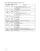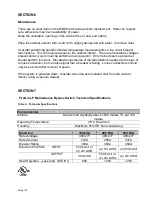
Page | 12
Control Connections
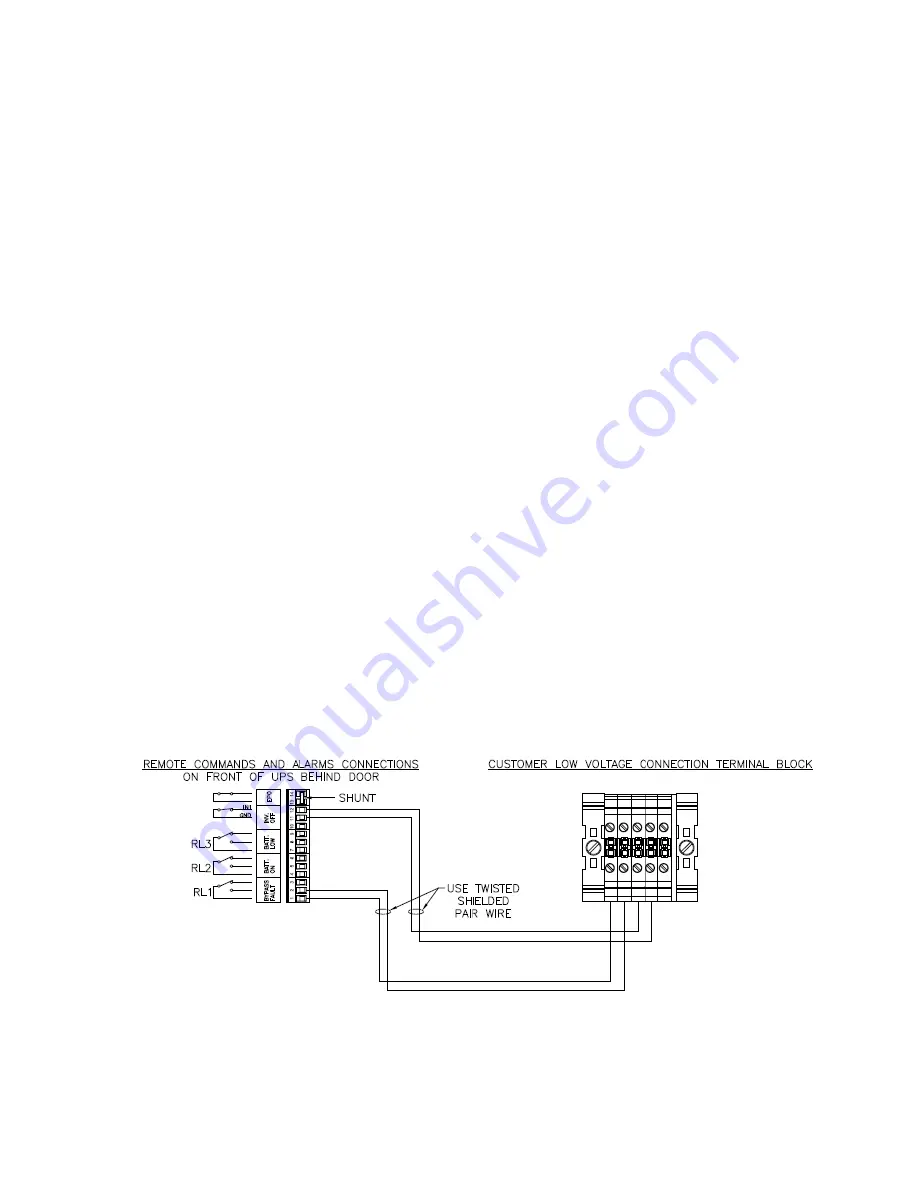
Four control connections must be made between the Maintenance Bypass Switch Cabinet
(MBS) and the UPS in order to provide backfeed protection, a required safety feature
The wiring to these low voltage (“ELV”) connections must be kept separated from the
higher voltage wiring. Refer to
Figure 4
regarding the Low Voltage Terminal Block and to
the UPS manual that shows the connection point in the UPS.
Connections between the Maintenance Bypass Switch Cabinet and the UPS
Since these wires affect the operation of the UPS, they should be protected. Running them
in conduit is a good idea, even if local codes do not require conduit. It is also
recommended that the wires are shielded twisted pairs. Alpha 6010C is a shielded cable
with three twisted pairs and is available from a number of sources in various spool lengths.
Two pairs are required:
Pair 1 - First wire from terminal 2 of the Low Voltage Connection Terminal Block (LVTB) of
the Maintenance Bypass Switch Cabinet to terminal 11 of the Remote Commands and
Alarms Connections on the UPS (RCA-UPS). Second wire from terminal 1 of LVTB to
terminal 12 of RCA-UPS.
Pair 2 – First wire from terminal 3 of LVTB to terminal 1 of RCA-UPS. Second wire from
terminal 4 of LVTB to terminal 2 of RCA-UPS.
Figure 7
is an electrical wiring schematic summarizing the connections to the Low Voltage
Connection Terminal Block.
Terminal Strip Torque Requirements
The terminals on the Customer Low Voltage Connection Terminal Block must be torqued to
5.3 to 7.0 inch-lbs. The terminals on the Control Connections (on the UPS) must be torqued
to 4.4 inch-lbs.
Figure 6 - Customer Low Voltage Connection Terminal Block


