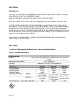
Page | 13
SECTION 5
Operation
Refer to the User's Manual for the UPS for instructions on operating the UPS part of the
system.
If the UPS is part of a parallel system, special operating instructions apply.
Maintenance Bypass Switch (MBS)
The purpose of the Maintenance Bypass Switch (MBS) is to facilitate servicing the UPS
without removing power from the load. The main functional components of the MBS are
three circuit breakers that are used as disconnect switches. We will designate them
“BKR1”, “BKR2”, and “BKR3”, but they are labeled “1”, “2”, and “3” above the breaker
handles on the front inner cover of the cabinet. The breakers each have three positions: off
(down), on (up), and tripped (in between off and on). To turn on a tripped breaker, reset
the breaker by pushing the handle down to the off position, then raise it to the on position.
If a breaker will not reset or trips as being turned on, the backfeed prevention interlock is
active and the proper conditions (as described below) will have to be present before the
breaker can be operated. When closed, BKR1 supplies power from the supply (utility) to
the bypass input of the UPS. For single input UPS configurations, it also supplies power to
the rectifier input. When closed, BKR3 connects the output of the UPS to the load. When
closed, BKR2 bypasses the path through BKR1, the UPS, and BKR3 and connects the
supply directly to the load. BKR2 and BKR3 must never be closed at the same time unless
the UPS is in bypass mode. It does not matter which type of bypass, but bypass via
SWMB is the simplest to engage. There are signals that support an interlock function to
prevent BKR2 from being closed unless BKR3 is open or the UPS is in bypass mode. For
the UPS to be able to issue this signal, the UPS controls must be powered. Always
observe proper switching sequence to avoid loss of power to the load Common switching
operations are also described, below. There are also some problem scenarios listed.
The three switches (Breaker 1, Breaker 2, and Breaker 3) have eight possible combinations
or "States".
Table 7
lists all of the possible states. Note that one possibility (Breaker 1
open, Breaker 2 and Breaker 3 closed) is forbidden as unexpected system behavior could
result, including loss of power to the load. The Overlap State is a transient state. It is the
"make" before the "break". Time spent in this state should be kept to a minimum as
external events could lead to tripping Breaker 2, possibly interrupting power to the load.
Also, please note that the UPS does not condition the power to the load while in bypass
and that battery back-up is not available while in bypass.
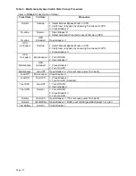
To avoid damage to the UPS and to avoid interrupting power to the load, the procedures
listed in
Table 8
must be used to change from one state to another. The MBS is equipped
with a label (see
Figure 8
) that describes the breaker sequences for two common
operations. The "To place load on maintenance bypass" sequence describes going from
Normal State to Overlap to UPS Unloaded to Maintenance. The "To place load on UPS"
sequence describes going from Maintenance State to UPS Unloaded to Overlap to Normal.


