Page | 8
SECTION 4
Electrical Installation
Overview
Each of the pieces of equipment covered by this manual has four sets of power
connections:
1. Input from the power source, typically, from the electric utility.
2. Power routed to the input of the UPS. If the bypass and rectifier inputs are powered
from separate sources, the bypass input must be fed from the MBS.
3. Power from the output of the UPS.
4. Power to the load
There are four control connections between the Maintenance Bypass Switch Cabinet and
the UPS that must be made. The required control connections are described later in this
section.
A user accessible disconnect device must be provided (by other’s) between the output of
this cabinet and the load. Refer to
Table 5
for current requirements.
WARNING
Only qualified service personnel (such as a licensed electrician) should perform
the installation and initial startup. There is a risk of electrical shock.
Wiring Preparation
1. Verify that the equipment is the proper type. The equipment covered by this manual
is 480 V 60 Hz input and output, only. The Maintenance Bypass Switch Cabinet
(MBS) can be used in delta-delta or wye-wye applications, but the UPS must be
properly configured (refer to the UPS manual). For delta-delta applications where an
input neutral is not provided, the output neutral connection must not be used and the
MBS to UPS neutral connections should be omitted.
2. Plan the locations of conduits. Two Conduit landing plates are provided at the top
(see
Figure 1
) and bottom of the cabinet. Connections between the MBS and UPS
must be made at the bottom. The landing plates in the rear must be used for the
power connections. As noted above, there are four sets of power connections and
one set of control connections. The low voltage control connection wires must be
routed through the bottom landing plate in the front of the cabinet to ensure physical
separation between them and the power wiring.
3. All wiring is to be in compliance with all applicable codes.
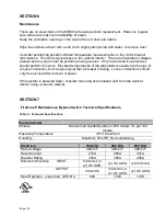
4. Verify that the source circuit capability is in compliance with the requirements shown
in
Table 3
and
Table 4
.


