


Note corresponding coloured labels
instALLAtion ProCedure
Be aware that the system you are installing may differ from the example below. A major point of difference is
that there may be 2 control units supplied. This is the case for example for dispensers with 3 taps, or systems
where 2 dispensers connect to a single chiller. The installation process for the second controller is the same as
shown below.
steP A - PLACe disPenser into the hoLe in the benCh
1. Uncoil the fluid product lines and data cables;
2. Lower Dispenser into the hole in the bench.
NOTE: The Dispenser will be set in place with
silicone or similar sealant in Step G.
steP b - ConneCt drAin hose
1. Push the drain hose onto the barb connector
underneath the sink and attach hose clamp;
2. Route the drain hose to a drain and cut hose
to length.
IMPORTANT:
For good drainage ensure adequate
fall and avoid sags in the hose. Ensure the end of
the drain hose cannot become submerged in the
drain.
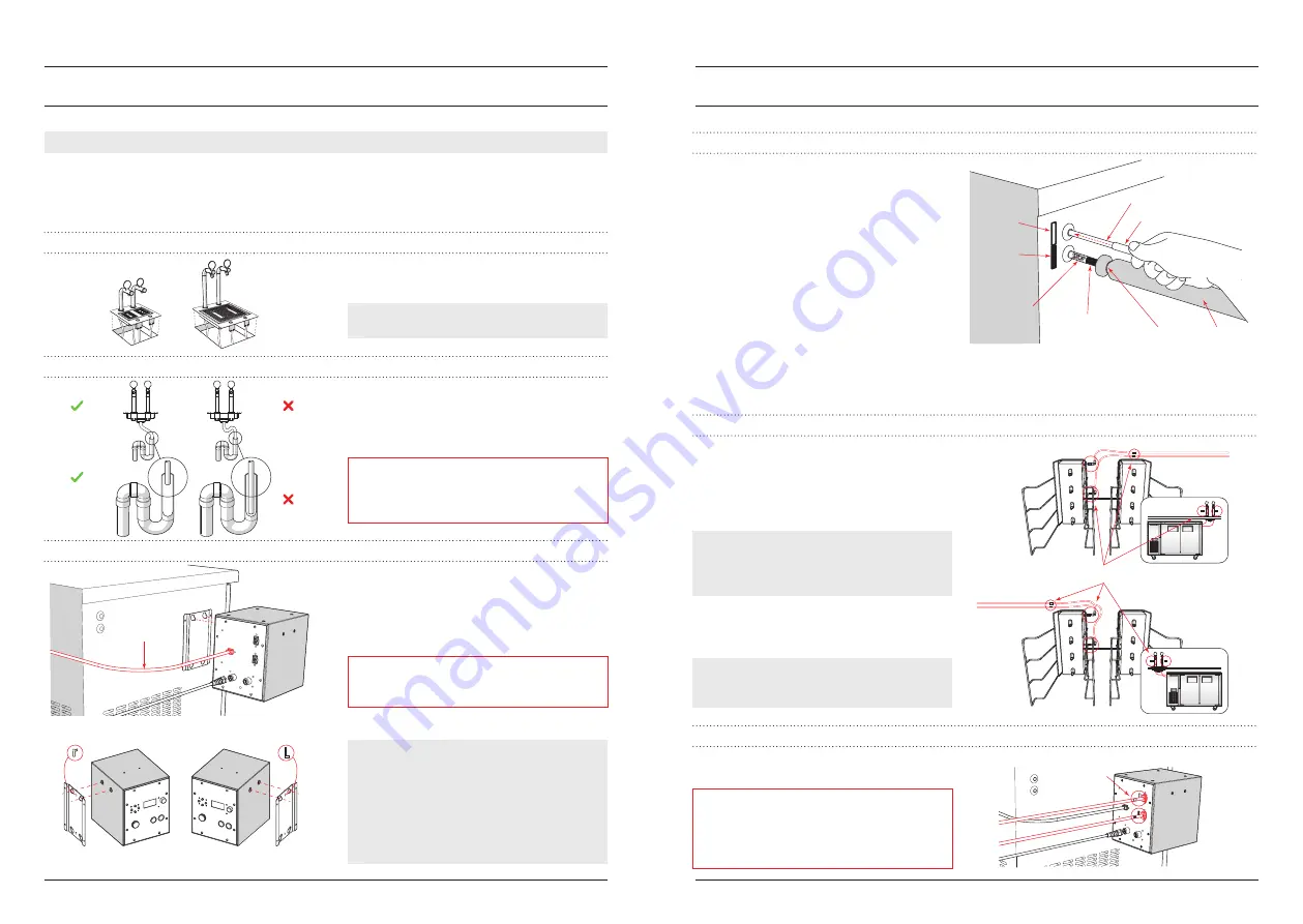
steP C - Mount ControL unit And ConneCt ControL to PuMP CAbLe
1. Mount the Control Unit on the Control Unit
mounting bracket;
2. Uncoil the Control to Pump cable from the
rear of the Chiller and connect to the rear of
the Control Unit;
IMPORTANT:
To avoid malfunction ensure the
small catch on the male connector clips over the
retaining lug on the female connector.
3. Push the Chiller into place.
NOTE: Freepour generally ships with the Control
Unit mounting bracket and Control to Pump cable
set for a LHS installation. If the Control Unit is to
be set on the RHS of the Chiller or elsewhere the
Control Unit mounting bracket can be removed
from the Chiller and repositioned. The Control to
Pump cable can also be rerouted in the conduit on
the rear of the Chiller.
Installation Overview & Procedure
l
13
12
l
Installation Overview & Procedure
steP d - ConneCt FLuid ProduCt Lines to ChiLLer
1. Feed the blue protective sleeves over the fluid
product lines. Push the sleeves firmly up to
the fitting at the base of the tap. Observe the
stickers on the protective sleeves showing the
tap and Chiller ends of the sleeve;
2. Feed insulation over the fluid product lines.
Fasten in place with cable ties at both ends;
3. Punch out the centre of the rubber openings
in the side of the Chiller (inside and outside)
and push the fluid product lines through
the openings until the STOP sticker on
the protective sleeve contacts the rubber
opening. It can be helpful to wet the product
lines with water and dishwashing soap before
pushing them through the openings.
steP e - ConneCt FLuid ProduCt Lines inside ChiLLer
To account for all Freepour variants, fluid product
lines are supplied long and need to be cut before
connecting to the manifold inside the Chiller.
1. Determine the length for the fluid product
lines inside the Chiller and cut them to length;
NOTE: The length of the fluid product lines inside
the Chiller is correct when they are not too long
and risk being kinked inside the Chiller and not
too short making connection difficult.
2. Plug '
A'
fluid product line into the top
connector on the manifold and '
B'
fluid
product line into the lower connector.
NOTE: Ensure that the fluid product lines are
pushed FULLY into the fittings in the side of the
manifold so this connection does not leak.
steP F - ConneCt dAtA CAbLes
1. Connect the data cables (mentioned in STEP
A) to the rear of the Control Unit.
IMPORTANT:
Ensure the small catch on the male
connector clips over the retaining lug on the
female connector. If this catch does not engage,
the connector may slowly uncouple and cause the
machine to malfunction.
Control
to Pump
cable
Mounting
bracket
Drain hose
not sagging
Drain hose
correct length
Drain hose
sagging
Drain hose
too long
Tap A
coloured label
Tap B
coloured label
Coloured labels are used to identify all fluid and data connections.
Ensure you connect fluid lines and data cables into connectors
with corresponding coloured labels.
Cable tie
Tap B
coloured label
Insulation
STOP sticker
on protective
sleeve
Protective sleeve
Fluid product line
Note corresponding
coloured labels
Summary of Contents for Freepour
Page 16: ......


