background image

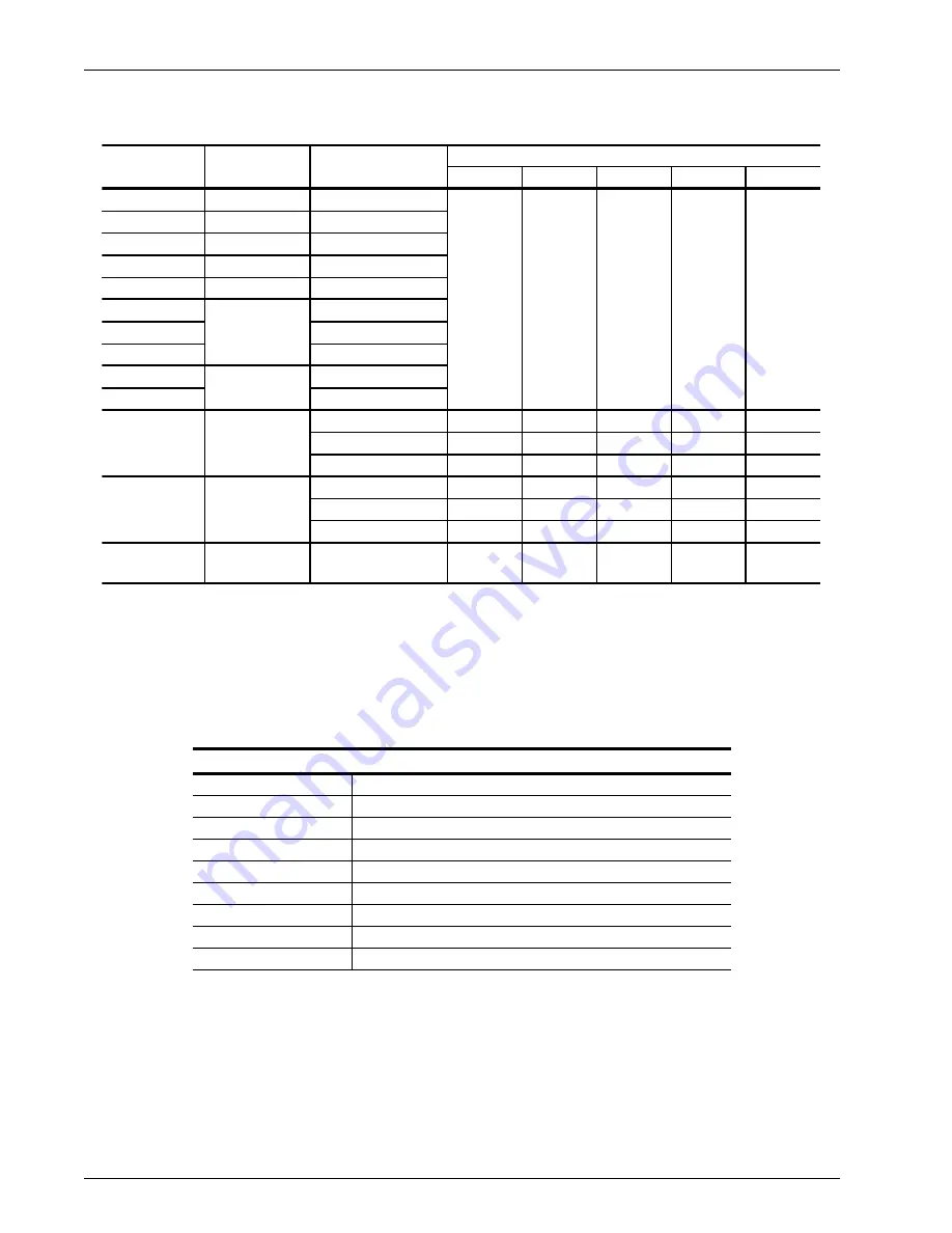
6x84

6x72

6x48

6x36

6x24

410SS

LL900127

CELCON

LL900129

BRASS

LL916284

17-7 SS

LL900124

PEEK

LL118683

410SS

LL125801

BRASS

LL918089

17-7 SS

LL919100

CELCON

LL900133

PEEK

LL121856

N/A

8

4

N/A

2

128675M1

N/A

2

2

N/A

N/A

128675M2

N/A

2

2

N/A

N/A

LL926752

N/A

8

4

N/A

2

LL926752M1

N/A

2

2

N/A

N/A

LL926752M2

N/A

2

2

N/A

N/A

POLY

For 5-1/4” 
shaft only

LL3005185

N/A

12

8

N/A

2

HE100-004

QUANTITY

MATERIAL

REMARKS

PART NO.

DELRIN

16

12

8

For 5-1/4” 
shaft only

For 5-1/4” 
shaft only

28

24

410SS

Open Style 

with holes

Open Style

PART NUMBER

DESCRIPTION

LL927603

Corrosion Prevention

LL725499

Caution/Warning Shaft Guard

LL119170

Danger - Contents Under Pressure

LL125098

3-A Label

LL119169

Safety Instructions

LL930514

SPX/WCB Logo Horizontal

LL930513

SPX/WCB Logo Vertical

LL931360

Caution/Warning Product Head Locking Latch (Vertical)

LL931407

Caution/Warning Product Head Locking Latch (Vertical)

Parts Lists

Waukesha Cherry-Burrell 

Page 78

95-03057

11/2012

Votator II Blades

Labels

Summary of Contents for Votator II

Page 1: ...FPO INSTRUCTION MANUAL Votator II SCRAPED SURFACE HEAT EXCHANGER FORM NO 95 03057 REVISION 11 2012 READ AND UNDERSTAND THIS MANUAL PRIOR TO OPERATING OR SERVICING THIS PRODUCT...

Page 2: ...any means electronic or mechanical including photocopying and recording for any purpose without the express written per mission of SPX Corporation Copyright 2005 2012 SPX Corporation All Rights Reserv...

Page 3: ...hanical Seal Design 11 Flush Fluid Requirements 12 Piping 12 Guidelines for Piping 12 Suggested Media Piping for Steam 12 Suggested Media Piping for Water or Liquid 13 Refrigeration Piping Installatio...

Page 4: ...artup Procedure 35 Heating Liquid Cooling Applications 35 Refrigeration Applications Pumped and Gravity Systems 35 Shutdown Procedure 36 Preventing Tube Scoring 36 Maintenance 37 Routine Maintenance C...

Page 5: ...condary Seal Head Insert Removal and Installation 58 One Piece Primary Seal Body Rotating Seal Face 59 Removable Seal Body Insert Rotating Seal Face 59 Assembly of Removable Primary Seal Body 59 Assem...

Page 6: ...t limitation any warranty of merchantabil ity of fitness for a particular purpose The foregoing sets forth Seller s entire and exclusive liability and Buyer s exclusive and sole remedy for any claim o...

Page 7: ...pment before working on or near exposed circuit parts Locking and Interlocking Devices These devices should be checked for proper working condition and capa bility of performing their intended functio...

Page 8: ...ch do not exceed concentrations of 150 ppm available chlorine do not exceed contact time of 20 minutes and do not exceed temperatures of 104 F 40 C Corrosion discoloration deposits or pitting may occu...

Page 9: ...uter tube is called the jacket and contains working fluid to heat or cool the contents of the inner product tube The product tube provides a heat exchange surface for the product Standard product tube...

Page 10: ...tions for Vertical Votator II The Vertical Votator II cylinder assembly is shipped for on site installation on the mounting pole When receiving the shipment check for the following or multiples of dep...

Page 11: ...leveled lengthwise along the length of the cylinder and crosswise by adjusting the feet on the legs For units that will perform CIP set the level for a forward pitch of 0 3 degrees 1 16 inch per foot...

Page 12: ...nical Seal Design on page 11 for units furnished between 2005 and 2012 See 2012 Mechanical Seal Design on page 11 for standard units finished from 2012 to the present Certain Votator II units have als...

Page 13: ...12 Mechanical Seal Design Standard units furnished starting in 2012 have removable rotary seal faces in solid carbon silicon carbide tungsten carbide and narrow face tungsten carbide materials The sta...

Page 14: ...y valve to protect jacket Provide temperature indicators on both sides of Votator II unit Provide pressure gauge on discharge side of pump When using liquid coolant provide a method to introduce heati...

Page 15: ...urce flow to the actual heat exchange requirements to provide maximum control of the process Figure 9 Suggested Media Piping Water or Liquid TC TY TE TI TI PI MS TI PI TI 1 2 3 4 5 6 7 HE100 057 Table...

Page 16: ...rated capacity of cylinder Do not connect to a header already in use by other equipment with widely varying loads CAUTION A suction trap or auxiliary receiver should be installed in the line to preve...

Page 17: ...liquid refrigerant and modulates or shuts off the liquid flow Minor adjustments in the level response can be made by adjusting the spring tension of the expansion valve seat If a refrigerant level flo...

Page 18: ...solenoid valve when opened allows liquid refrigerant to flow into the jacket of the heat exchanger The flow is regulated by a manually set flow control valve Cooling is achieved when the pressure cont...

Page 19: ...receiver is stored in a surge drum located above the Votator II The level in the surge drum is automatically controlled by the level system provided with the equipment Gravity forces the refrigerant...

Page 20: ...l Switch 3 High Pressure Regulating Valve see Item 14 14 Dual Pressure Regulating Valve includes Items 2 3 and 20 4 To Low Pressure Receiver 15 Hot Gas Reducing Valve 5 6 Electric Control Signal or In...

Page 21: ...le for correct sizing of starter coil and thermal overload protection based on motor nameplate voltage frequency FLA s service factor and horsepower X 2 2 3 3 3 1 1 Current sensing relay and plug in b...

Page 22: ...Freeze Protection Components CURRENT SENSE RELAY CURRENT METER II XX 1 2 3 4 5 6 7 9 8 10 11 TRIP CURRENT ADJUST SLIGHTLY BELOW MAXIMUM OR FULL LOAD FINE TUNING TO BE DONE AT SYSTEM STARTUP SEE PRODUC...

Page 23: ...Cherry Burrell Installation 11 2012 95 03057 Page 21 Gravity Refrigeration with Level Master Control LMC Figure 14 Suggested Electrical Schematic Gravity Refrigeration with Level Master Control LMC HE...

Page 24: ...Installation Waukesha Cherry Burrell Page 22 95 03057 11 2012 Gravity Refrigeration with Level Switch Figure 15 Suggested Electrical Schematic Gravity Refrigeration with Level Switch HE100 108...

Page 25: ...Waukesha Cherry Burrell Installation 11 2012 95 03057 Page 23 Liquid Overfeed Refrigeration System Figure 16 Suggested Electrical Schematic Liquid Overfeed Refrigeration System HE100 102...

Page 26: ...pressurize to 40 to 50 psig then close valve 6 Check again for leaks at front back and all piping connections Special Considerations for Vertical Votator II The customer is responsible for securing t...

Page 27: ...rior to use vibrations during shipment may cause them to loosen Check and Adjust Hydraulic Cylinder After heat exchanger cylinders are mounted to the pole check to ensure the proper distance is mainta...

Page 28: ...is fully clockwise Valve is locked in place with a 9 16 jam nut and adjusted with a 5 32 Allen Head set screw It maintains pressure on hydraulic cylinder when hydraulic pump is off or in neutral posit...

Page 29: ...the Votator II cylinders A crane or other lift device is needed to lift the accumulator mounting bracket in place for installation Lift the mounting bracket in place with a sling Bolt the accumulator...

Page 30: ...T APPLICATION ONLY 6 x 36 CYLINDER DIM A DIM B DIM C 6 x 48 6 x 72 119 9 16 3037mm 59 7 8 1521mm 61 1 2 1562mm 95 9 16 2427mm 35 7 8 911mm 37 1 2 952mm 83 9 16 2122mm 23 7 8 606mm 25 1 2 648mm CYLINDE...

Page 31: ...RELIEF VALVE 1 FPT 3 SUCTION OIL DRAIN 3 4 FPT ELEC CONN 1 2 FPT EQUALIZER CONN 1 4 FPT 5 8 DIA 2 HOLES 16 406mm CYLINDERS DIM A 104 2642mm 6 3 16 171mm 20 508mm 2 1 6 7 8 175mm 96 2438mm NUMBER OF D...

Page 32: ...R BY CUSTOMER BY SEE DETAIL 4 FLOOR PIPE BY CUSTOMER WELDED BY CUSTOMER DETAIL ITEM 4 A S M E BOILER AND PRESSURE VESSEL CODE ACCUMULATORS BEARS A S M E STAMP FOR COMPLIANCE WITH NOTES DETAIL ITEM 2 H...

Page 33: ...715mm 36 914mm 43 1 2 1105mm DIM H FRAME SINGLE ROW 2 CYL 38 965mm 18 457mm 40 1016mm 1 OVER 1 2 CYL NA 54 1372mm 36 914mm DIM D 30 762mm NA NA 40 3 4 1035mm 22 3 4 578mm DIM K DIM A DIM E BETWEEN CEN...

Page 34: ...ED LOOSE WITH UNIT 6 SEE VII HYDRAULIC SCHEMATIC BOTTOM OF THE POLE TO BE SECURED TO THE FLOOR WITH A 3 4 INCH LAG BOLT OR 3 4 STUD WITH A NUT ON IT RESERVOIR NOT SHIPPED WITH HYDRAULIC OIL CUSTOMER W...

Page 35: ...Waukesha Cherry Burrell Installation 11 2012 95 03057 Page 33 Vertical Hydraulic Schematic B A P T M CYLINDER DIRECTIONAL VALVE POWER UNIT COUNTER BALANCE VALVE HE100 051...

Page 36: ...temperature and pressure are at required values and there is an adequate supply of heating cooling media Check to determine if product is available and pressures are at required values For Refrigerat...

Page 37: ...d and Gravity Systems 1 Start product pump using product or compatible liquid such as water 2 After product flow is established start Votator II mutator shaft motor Do not run Votator II without produ...

Page 38: ...provide a surge tank or a recirculation line With continuous operations a steam line connected to the product line can enable steam to soften and remove product in the tube at shut down The final opt...

Page 39: ...m lift cradle or remove two scraper blades from mid section of mutator shaft and raise mutator shaft so that the center of one set of blade pins is positioned in the middle of the bayonet ring 9 Insta...

Page 40: ...aft in the unit carefully guide the blades in the cylinder while the mutator is raised It may be necessary to turn the mutator shaft slightly to align the spline in the motor drive WARNING To avoid in...

Page 41: ...quire replacement refer to pages 56 and 72 or pages 57 and 70 When assembling the single mechanical seal place the wave spring on the shaft followed by the seal backing ring and the u cup with the ope...

Page 42: ...east once a week Always use the removal trough skid to avoid bottom blades scoring the heat transfer tube Replace the mechanical seal shell O rings Product Tube Inspect the tube s inner chrome surface...

Page 43: ...en Mutator Shaft Bearing The Votator II has only one serviceable ball bearing assembly located in the Opposite Drive End Head of the unit Lubrication of this bearing while in service is done through t...

Page 44: ...Table 6 The gearbox SK 4282 or SK 5282 is indicated on the identification plate Blades Blades that have developed a heel greater than WCB specifications should be sharpened per instructions in this ma...

Page 45: ...done by an ASME coded machine shop with certified welders will void the warranty and possibly void insurance SPX has all required certifications necessary for repair of ASME coded parts The removable...

Page 46: ...such as salt sugar detergents etc Using dull blades or blades that have been sharpened below minimum width specifications Using blades other than those furnished by Waukesha Cherry Burrell Worn mutato...

Page 47: ...Remove the O rings and clean the grooves thoroughly of all residue and buildup Care must be taken in cleaning the flanges as they are part of the seal mechanism of the unit Install new O rings any ti...

Page 48: ...ure 25 The blades must be maintained to achieve maximum performance When the heel of the blade reaches a maximum of 1 16 1 6 mm on metal blades or 1 8 3 2 mm on plastic blades they must be replaced or...

Page 49: ...eaded See Figure 27 7 Insert HRT as shown in Figure 28 and slide the head and bearing off the shaft to protect the stationary seal face during disassembly Figure 28 Use of Head Removal Tool HRT HE100...

Page 50: ...aintenance on page 56 4 Install all scraper blades on mutator shaft NOTE Blades should be kept in the same position on mutator shaft throughout life of blade Make sure blades are removed and reinstall...

Page 51: ...etainer and secure with clamp 14 Install shaft nut onto shaft nut is left hand threaded and tighten nut against bearing s inner race 15 Lift the shaft and head place over the tube ring and position ba...

Page 52: ...9 6 Take four 4 bolts and thread them into the B holes The B holes are located at the 12 3 6 and 9 o clock locations DO NOT TIGHTEN 7 Using an X pattern gradually tighten bolts to withdraw tube from j...

Page 53: ...nstall latch hardware 10 Install drive end head 11 Install shaft with mechanical seals 12 Install opposite drive end head Maintenance of Vertical Votator II DANGER Before doing any maintenance work on...

Page 54: ...end of shaft out of unit 11 Place shaft and head assembly on a table or suitable frame for servicing 12 Scraper blades can be removed and serviced at this time Shaft Installation Vertical Unit 1 Chec...

Page 55: ...e splines are meshed correctly 11 Continue to raise shaft until head is about six 6 inches from being engaged 12 Once the last set of blades has been started in tube remove alignment tool if used 13 C...

Page 56: ...nder to allow tube to move down NOTE Tube may slide out easily or it may need coaxing out 10 Lower lift arm slightly to allow tube to move down At the 12 6 3 and 9 o clock positions tube flange is thr...

Page 57: ...d 13 Lubricate and install new O rings on both ends of tube 14 Install new packing ring on steam or liquid tubes 15 To reinstall tube reverse the procedure 16 Torque bolts to 240 in lbs 20 ft lbs NOTE...

Page 58: ...new insert lubricate the o rings and the inside bore Insert in the head with an even distribution of force on the face The face must be protected with plastic to avoid damage Seal Body Insert Rotatin...

Page 59: ...own see Double Mechanical Seal on page 70 Units furnished before 2005 had a removable seal body insert as described below In 2005 all single and double mechanical seals were furnished with a one piece...

Page 60: ...nsert or use a soft cloth to catch it to prevent it from dropping when removed NOTE To prevent damage to the seal face do not place seal face down on any surface during maintenance To install a new pr...

Page 61: ...housing Figure 65 4 Vent trapped air by placing a small flat screwdriver blade between seal ring and outside O ring NOTE Air can be become trapped behind Primary Seal Insert after assembly This air mu...

Page 62: ...32 inches 0 015 above the stub shaft surface The secondary seal body is held in place by one seal drive pin It should be 3 32 inch 0 015 above the stub shaft surface It is extremely important that th...

Page 63: ...rvicing the seal The bottom mechanical seal can be serviced with the mutator shaft in the unit by using the shaft clamp See Figure 72 1 Lower shaft approximately two 2 feet or to a convenient height 2...

Page 64: ...d shaft nut guard 9 While supporting head remove shaft nut Nut is left hand threaded 10 Grasp head with both hands remove it from shaft 11 Seals can now be serviced See Mechanical Seal Maintenance on...

Page 65: ...acer 3 LL2200321 39 Stud 1 LL2200277 40 Hexagon Head Shoulder Screw 1 LL925499 52 Spacer Washer 1 LL931315 APPLICATION DESCRIPTION PART Opposite Drive End Concentric 3 I Line LL923245 Concentric 3 Fla...

Page 66: ...057 11 2012 Cylinder Assembly HE100 039b 19 20 21 23 22 13 15 12 14 16 36 24 25 19 20 21 22 23 Extra Heavy Duty Bearing Option B 23 21 19 20 HE100 124 B 26 22 24 Spider Head Option obsolete after 2009...

Page 67: ...Heavy Duty Votator II obsolete after 2009 LL118393 Extra Heavy Duty Votator II Current design 128476 19B Clamp Ring 1 Spider Head Only LL117678 20 Shaft Nut Guard 1 Horizontal LL923212 W Shaft Heater...

Page 68: ...1 4 dia NA 5 1 4 dia NA 6 x 48 Single Mechanical 2 1 2 dia LL935987 Double Mechanical 2 1 2 dia NA 4 dia LL936764 4 dia LL936743 4 1 2 dia LL936765 4 1 2 dia LL936786 5 1 4 dia LL935921 5 1 4 dia NA E...

Page 69: ...ECC NI CR NA 6 X 72 BWS UM NI CR 600 PSI LL929756 UM 316 SS TW WO RINGS LL929263 UM 316 SS TW CR WO RINGS LL930735 UM CS CR LL121057 UM ECC NI CR LL935827 UM ECC TW CR WO RINGS LL123513 UM OVAL NI CR...

Page 70: ...Cherry Burrell Page 68 95 03057 11 2012 2012 Double Mechanical Seal 32 4 11A 44 3 1 5 7 45 6 7A 9 10 8 11 HE100 113 43 HE100 116 HE100 115 ODE Head Installation Removal Tool LL121191 Seal Installation...

Page 71: ...eat installation Used on Double Mechanical Seal only ITEM DESCRIPTION QTY PER SEAL MATERIAL OPTION PART 1 Spring VII Product Seal Wavy Washer 1 Standard LL922313A 3 O ring 1 Buna N75237 EPDM E70237 FK...

Page 72: ...Parts Lists WaukeshaCherry Burrell Page 70 95 03057 11 2012 Double Mechanical Seal 6 4 11A 11 32 44 43 45 1 3 10 7 5 HE100 114 HE100 116 ODE Head Installation Removal Tool LL121191...

Page 73: ...934871 5 Seal Body Secondary if required 1 All LL932357 6 Seal Head Insert O ring Primary 2 Buna N75044 Fluoroelastomer V70044 680 EPDM E70044 7 Seal Head Insert Primary 1 Ceramic LL934873 10 One Piec...

Page 74: ...Parts Lists WaukeshaCherry Burrell Page 72 95 03057 11 2012 Single Mechanical Seal...

Page 75: ...r LL700014A08 EPDM LL700014A03 3 Seal Keeper O ring 1 Buna N75226 Fluoroelastomer V70226 680 EPDM E70226 4 Flushing Lip Seal 1 All LL925472 5 Retaining Ring 1 All LL930685 6 Seal Head Insert O ring 2...

Page 76: ...Parts Lists WaukeshaCherry Burrell Page 74 95 03057 11 2012 Vertical Refrigeration Piping...

Page 77: ...AR 2 1 2 Male LL700017A62 10 Refrigeration Flange Gasket AR 2 1 2 LL710260 11 Square Head Machine Bolt 4 per flg 3 4 10 x 3 1 2 Lg LL723931 12 Hex Nut 4 per flg 3 4 10 LL710112 13 S W Refrigeration F...

Page 78: ...r Kit Only 1 LL928737 1 16 Shaft Stop Clamp 1 4 Shaft LL935529 4 1 2 Shaft LL931279 5 1 4 Shaft LL935191 22 Hydraulic Cylinder 1 6 x 24 Cylinder LL121897 6 x 36 Cylinder LL121898 6 x 48 Cylinder LL121...

Page 79: ...24 Cylinder 1 LL123001 6 x 36 Cylinder 1 LL112278E 6 x 48 Cylinder 6 x 72 Cylinder 6 x 84 Cylinder 49 Heater Pipe Support 6 x 24 Cylinder 1 LL936930 6 x 36 Cylinder 1 LL934075 6 x 48 Cylinder 1 LL936...

Page 80: ...QUANTITY MATERIAL REMARKS PART NO DELRIN 16 12 8 For 5 1 4 shaft only For 5 1 4 shaft only 28 24 410SS Open Style with holes Open Style PART NUMBER DESCRIPTION LL927603 Corrosion Prevention LL725499...

Page 81: ...ulator and other oil separators oil legs or pots in refrigeration system Steam on jacket super heated Use only dry and saturated steam Oil deposits on transfer tube Remove heat transfer tube and clean...

Page 82: ...correct O ring contact WCB Damaged seal head insert Replace entire seal Recess in head for seal head insert damaged Contact WCB for repair instructions Leakage across seal body O ring twisted when ins...

Page 83: ...rn or missing Replace with new seal drive pin Seal retaining ring out of place Inspect retaining ring and lip seal Replace as necessary Insufficient spring pressure to hold body and insert together af...

Page 84: ...hooting Chart on page 79 for cause and solution aids Water and Air in Refrigeration System Water and ammonia combine to form ammonium hydroxide which combines with oil to form sludge Sludge is extreme...

Page 85: ......

Page 86: ...nges without notice or obligation Design features materials of construction and dimensional data as described in this bulletin are provided for your information only and should not be relied upon unle...

Reviews: