16
Commissioning
7.4.3.2 Maximum Current Mode
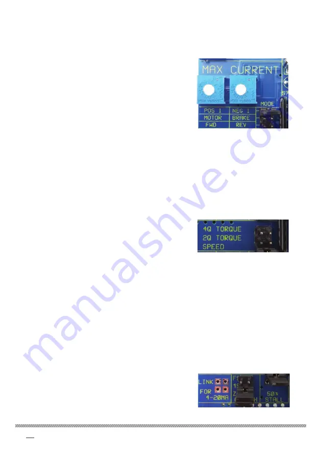
There are three link positions which determine the function of the MAX CURRENT
presets (P6 and P10).
POS I/NEG I:
When the link is in this position, P6 sets the
positive current limit and P10 sets the negative
current limit irrespective of the direction of
rotation of the motor. This is the default position.
MOTOR/BRAKE:
With the link in this position, P6 sets the current
limit when motoring and P10 sets the current
when generating irrespective of the direction of
motor rotation and the polarity of current.
FWD/REV:
With the link in this position, P6 sets the current limit in the forward direction and
P10 sets it for the reverse direction irrespective of the polarity of current or whether
motoring or regenerating.
4Q TORQUE:
When the link is in this position, the voltage on T6
sets the maximum positive and negative currents
(±5V = ±100% of calibrated current).
2Q TORQUE:
With the link in this position, the voltage on T6 sets the maximum positive current (+10V
= +100% of calibrated current). The maximum negative current is only limited by the
setting of the negative current preset.
SPEED:
With the link in this position, the voltage on terminal 6 is an auxiliary input to the speed
loop demand summing amplifier that bypasses the ramp. Positive for forward rotation.
Refer to "8.1 Torque Control Mode" on page 20.
7.4.3.4 4/20 mA and 0/20 mA Modes
There are two links which can be used to configure the unit for current loop operation
with T2 the input and T5 the return.
If just the lower link is fitted 0 - 20 mA operation is
selected. With both links fitted 4 - 20 mA operation
is possible but only if the MIN SPEED preset is
adjusted such that there is a 250 Ω resistance
between T2 and T5.
7.4.3.3 Torque/Speed Mode
There are three positions for this link which determine the function of the AUX
analogue input on T6.


