background image

DR

AFT

35

Spohn & Burkhardt 

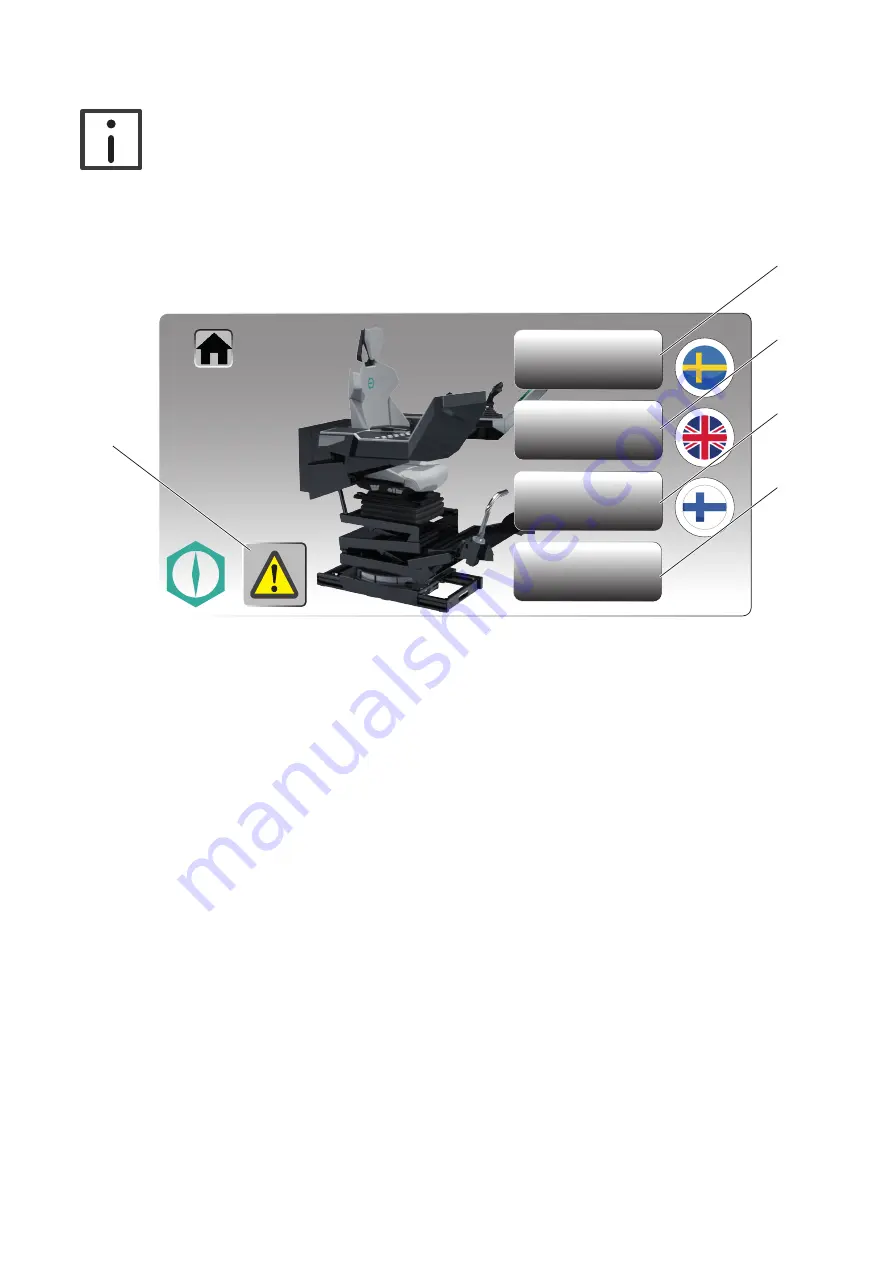
3.3.6. Motor supervision

Note

The settings for monitoring the motors are configured by Spohn & Burkhardt before the 
delivery of the control stand and are not allowed to be changed. For changes to the mo-
tor settings, contact Spohn & Burkhardt (

for address see Imprint, page 2

).

Figure 10. 

Sensor settings

User Admin.

System settings

Motor

supervision

6.14

6.15

6.17

6.16

6.18

Administrator – Motor supervision (actual product may vary from figure)

1.  Log in as the administrator, 

see section 3.3.1 "Administrator login", page 31

.

2.  Press the touch-button (

6.17

) "Motor supervision".

• The page for monitoring the motors and motor cards appears on the display (

6

).

Summary of Contents for FSMMD

Page 1: ...Steuerstand FSMMD Control Stand FSMMD Betriebsanleitung Operating Instructions DRAFT ...

Page 2: ...u Schadenersatz Alle Rechte für den Fall der Patent Gebrauchsmuster oder Designeintragung vorbehalten Version 12 2020 Imprint Impressum Spohn Burkhardt GmbH Co KG Mauergasse 5 89143 Blaubeuren Germany Spohn Burkhardt GmbH Co KG Mauergasse 5 89143 Blaubeuren Germany Subject to further development and technical changes without notice Changes mistakes and printing errors do not justify any claims for...

Page 3: ...Montage im Einbauraum 16 3 2 Elektrischer Anschluss 18 4 Inbetriebnahme 20 4 1 Funktionsprüfung 20 5 Bedienung 21 5 1 Einstellung Arbeitsposition elektrisch 21 5 2 Einstellung Arbeitsposition manuell 23 5 2 1 Sitz und Sitzkissen einstellen 23 5 2 2 Pultpositionen einstellen 23 5 2 3 Stierhörner Fußstützen 24 5 3 Memory System Arbeitsposition speichern 25 5 4 Memory System Gespeicherte Arbeitsposit...

Page 4: ... 6 1 4 Motorteile und Motorspindel schmieren 31 6 2 Komponenten 31 7 Reparatur 32 7 1 Steuerstand 32 7 2 Komponenten 32 8 Ersatzteile 32 9 Demontage 32 9 1 Elektrischen Anschluss lösen 32 9 2 Mechanische Demontage 33 9 2 1 Vorarbeiten 33 9 2 2 Demontage aus dem Einbauraum 35 10 Entsorgung 36 11 Mitgeltende Dokumente 36 12 Einbauerklärung 37 ...

Page 5: ...erstanden haben Diese Betriebsanleitung muss allen Personen die mit und an dem Gerät arbeiten stets in einem leserli chen Zustand zur Verfügung stehen Für Schäden aus einer nicht bestimmungsgemäßen Verwendung sowie eigenmächtigen Veränderun gen am Gerät die zu Personen oder Sachschäden führen übernimmt der Hersteller keine Haftung 1 3 Fachpersonal Alle Arbeiten an dem Gerät sowie die Einbindung de...

Page 6: ...wei se von allen Personen die mit und an dem Gerät arbeiten beachtet und eingehalten werden Gefahr durch elektrischen Stromschlag Beachten Sie vor allen Arbeiten am Gerät die fünf Sicherheitsregeln in der folgenden Rei henfolge Freischalten Gegen Wiedereinschalten sichern Spannungsfreiheit prüfen Erden und Kurzschließen Benachbarte unter Spannung stehende Teile abdecken oder abschranken Quetschgef...

Page 7: ...erden Gefahr Ist ein Sicherheitsgurt vorhanden muss dieser vor dem Arbeitseinsatz angelegt werden Nach einem Unfall muss die Funktion des Sicherheitsgurtes überprüft werden Ist die voll ständige Funktion nicht gewährleistet muss der Sicherheitsgurt getauscht werden Bei Sicherheitsgurten mit zusätzlichem Kontakt ist vor jedem Arbeitseinsatz die elekt rische Funktion zu prüfen Ist die vollständige F...

Page 8: ...betätigt werden Vorsicht Vor jeder Arbeitsaufnahme muss die Funktionsfähigkeit des Steuerstandes geprüft wer den Vorsicht Um Langzeitschäden oder Ermüdungserscheinungen durch eine falsche Arbeitsposition zu vermeiden stellen Sie vor Arbeitsbeginn die für Sie optimale Arbeitsposition ein Achtung Achten Sie darauf dass alle Leitungen ordnungsgemäß ohne Knicke und Scheuerstellen verlegt sind Achten S...

Page 9: ... Durch die Berück sichtigung aller ergonomischen Anforderungen ermöglichen die Steuerstände FSMMD ein entspann tes und ermüdungsfreies Arbeiten Die Sitz und Pultpositionen sind elektrisch längs höhen und nei gungsverstellbar Die Steuerstände FSMMD ermöglichen eine konstante Arm und Sitzhaltung durch das optimale Zusammenspiel von Sitz Pult und Federung Mit dem Memory System lassen sich 5 verschied...

Page 10: ...DRAFT 10 Spohn Burkhardt 2 1 Übersicht Abbildung 2 1 2 6 4 22 14 11 11 18 12 10 13 23 16 16 15 5 3 12 17 7 9 7 3 4 18 19 17 18 20 19 21 8 Steuerstand FSMMD Übersicht Beispiel ...

Page 11: ... Stierhörner schwenken Fußstützen 8 Klemmhebel Längsverstellung Pult 20 Schaltschrank 9 Bedienelemente 21 Sitzunterbau 10 Pultunterteil Hutze 22 Federung 11 Pultträgersystem 23 Drehkranz 12 Monitor 1 2 2 Technische Daten Hinweis Die technischen Daten für weitere Varianten und individuelle Anpassungen entnehmen Sie dem zugehörigen Maßbild und dem zugehörigen Datenblatt siehe Kapitel 11 Mitgel tende...

Page 12: ...e Seite 36 2 3 1 Maße Einstellungen Arbeitspositionen Abbildung 3 1225 340 112 min 447 max 531 min 408 max 602 Ø 15 30 min 15 max 16 1 3 8 mi n 14 m ax 1 0 m in 1 4 m a x 4 5 m in 7 m a x 2 4 m i n 4 m a x 6 5 m a n u e l l min 205 max 346 111 850 Ø 2 0 5 5 4 5 min 1099 max 1199 1249 1349 min 180 max 330 manuell Maße Einstellungen Arbeitspositionen Maße in mm ...

Page 13: ...DRAFT 13 Spohn Burkhardt 2 3 2 Einbaumaße Abbildung 4 360 300 888 519 62 Ø 9 Ø 600 Ø 9 60 120 120 30 Einbaumaße Maße in mm ...

Page 14: ...ksichtigung der ein schlägigen Sicherheitsvorschriften durchgeführt werden Beachten Sie grundsätzlich die Sicherheitshinweise in Kapitel 1 Sicherheit Seite 5 3 1 Mechanische Montage 3 1 1 Vorarbeiten Abbildung 5 34 22 1 22 2 1 22 33 28 27 Vorarbeiten Sitz und Adapterplatte demontieren vereinfachte Darstellung ...

Page 15: ... 5 Lösen Sie die Senkkopfschrauben 34 und heben Sie die Adapterplatte 33 aus dem Steuerstand Abbildung 6 30 3 31 32 29 Vorarbeiten Pulte demontieren vereinfachte Darstellung Sollte der Zugang zum Einbauraum die Maße des Steuerstandes unterschreiten demontieren Sie zu sätzlich die Pulte 3 wie folgt Hinweis Sollte der Zugang zum Einbauraum die Maße des Steuerstandes unterschreiten wird die Verdrahtu...

Page 16: ...m geeigneten Hebewerkzeug Achten Sie beim Transport auf lose Teile des Steuerstandes 5 Befestigen Sie Hebebänder diagonal an mindestens 2 der in Abbildung 7 dargestellten Hebepunkte 6 Heben Sie den Steuerstand in den Einbauraum 3 1 2 Montage im Einbauraum Abbildung 8 24 23 25 14 Mechanische Montage ...

Page 17: ...rauben 27 und den Muttern 28 am Steuerstand Nur für Varianten mit pneumatischer Federung 10 Ziehen Sie den Gummibalg 22 1 nach oben 11 Verbinden Sie den Stecker 22 2 wieder mit der pneumatische Federung Variante mit Verfahrschlitten 1 Bereiten Sie ggf den Einbauraum vor 2 Positionieren Sie den Steuerstand am Einbauort achten Sie dabei auf den richtigen Mindestab stand zu benachbarten Bauteilen Der...

Page 18: ...en oder Steckern Buch sen verdrahtet Der elektrische Anschluss erfolgt individuell nach Anschlussplan den Vorgaben des Be treibers und den zugehörigen Stromlaufplänen siehe Kapitel 11 Mitgeltende Dokumen te Seite 36 1 Schalten Sie die Anlage spannungsfrei 2 Öffnen Sie den Schaltschrank 20 mit dem zugehörigen Schlüssel 20 1 3 Lösen Sie die Mutter der Kabelverschraubung 20 2 und schieben Sie die Mut...

Page 19: ...COMING AC 230V INCOMING DC 24V GENERALLY SUPPLY MOTORCARD 1 SUPPLY MOTORCARD 2 SUPPLY COMPRESSOR LUMBAR SUPPORT USB X01 102 101 PE PE 101 0 F01 102 0 F101 108 0 F102 108 0 F103 107 0 F104 101 0 N 2 001 002 003 X X 102 0 PE 101 0 1 2 1 2 1 2 1 2 Anschlussplan Abbildung 11 Elektrische Anschlüsse ...

Page 20: ...nbetriebnahme durch siehe Kapitel 4 Inbetriebnahme Seite 20 4 Inbetriebnahme Gefahr Alle Arbeiten am Gerät dürfen nur von Fachpersonal und unter Berücksichtigung der ein schlägigen Sicherheitsvorschriften durchgeführt werden Beachten Sie grundsätzlich die Sicherheitshinweise in Kapitel 1 Sicherheit Seite 5 4 1 Funktionsprüfung Gefahr Beschädigte Steuerstände dürfen nicht betrieben werden 1 Prüfen ...

Page 21: ...stellung der Arbeitsposition erfolgt elektrisch über Wipptaster 5 im rechten Pult 3 und ma nuell über Hebel und Taster sowie Stellräder am Sitz 1 Mit dem Memory System können die elekt rischen Einstellungen gespeichert und mit dem jeweiligen Bedien Code jederzeit abgerufen werden Der Bedien Code wird über das Display 6 des Memory Systems eingegeben Auf dem Display 6 des Memory Systems werden die f...

Page 22: ...r zurück zu bewegen Betätigen Sie den Wipptaster R um das rechte Pult nach oben oder unten zu neigen Betätigen Sie den Wipptaster L um das linke Pult nach oben oder unten zu neigen Betätigen Sie den Wipptaster um die Pulte nach oben oder unten zu bewegen Betätigen Sie den Wipptaster um den Sitz nach vorne oder hinten zu neigen Betätigen Sie den Wipptaster um den Sitz nach vorne oder hinten zu verf...

Page 23: ... der eingestellten Position festzustellen Um die Position des Sitzkissens 1 1 nach vorne oder hinten zu schieben gehen Sie wie folgt vor 1 Betätigen Sie den Hebel 1 3 und schieben Sie das Sitzkissen 1 1 nach vorne oder hinten 2 Lassen Sie den Hebel 1 3 los um den Sitz 1 in der eingestellten Position festzustellen 5 2 2 Pultpositionen einstellen Um die Position der Pulte 3 nach innen oder außen zu ...

Page 24: ...nd bringen Sie die Stierhörner Fußstützen 16 in die ge wünschte Position Achten Sie dabei darauf dass die Stierhörner Fußstützen 16 in der eingestell ten Position einrasten 3 Lassen Sie den Rastbolzen 17 los und arretieren Sie die eingestellte Position mit dem Rastbolzen 17 4 Ziehen Sie den Klemmhebel 18 wieder fest Um die Position der Stierhörner Fußstützen 16 nach außen oder innen zu schwenken g...

Page 25: ... mit Nummernblock 6 2 2 Geben Sie Ihren 4 stelligen Bedien Code über den Nummernblock 6 2 ein und bestätigen Sie den Bedien Code mit dem Touch Button Enter 6 4 Hinweis Mit dem Touch Button Zurück 6 3 können Sie eventuelle Tippfehler korrigieren 1 Stellen Sie die gewünschte Arbeitsposition gemäß Abschnitt 5 1 Einstellung Arbeitsposition elekt risch Seite 21 ein 2 Betätigen Sie einen der Touch Butto...

Page 26: ...lay 6 erscheint ein Bedienfeld mit Nummernblock 6 2 2 Geben Sie Ihren 4 stelligen Bedien Code über den Nummernblock 6 2 ein und bestätigen Sie den Bedien Code mit dem Touch Button Enter 6 4 Hinweis Mit dem Touch Button Zurück 6 3 können Sie eventuelle Tippfehler korrigieren 3 Auf dem Display 6 erscheinen die Touch Buttons 1 bis 5 6 5 für die unter diesem Bedien Code gespeicherten Arbeitspositionen...

Page 27: ...g 16 08 21 23 User 08 21 23 1 7 8 9 4 5 6 1 2 3 0 1 2 3 5 4 1234 6 3 6 2 6 4 6 8 6 9 6 Administrator Login Abbildung ähnlich Mit Auslieferung des Steuerstandes erhalten Sie einen Administrator Code Über diesen Code erhalten Sie Zugang zum Hauptmenü des Steuerstandes Melden Sie sich als Administrator wie folgt an 1 Betätigen Sie den Touch Button Logo 6 9 auf dem Display 6 Auf dem Display 6 erschein...

Page 28: ...025 26 1026 27 1027 28 1028 29 1029 30 1030 6 4 6 12 6 13 User password 6 Administrator Bedien Codes verwalten Abbildung ähnlich 1 Loggen Sie sich als Administrator ein siehe Abschnitt 5 5 1 Administrator Login Seite 27 2 Navigieren Sie durch das Menü wie folgt User admin administration Auf dem Display 6 erscheint die Seite zur Verwaltung 3 Betätigen Sie den Touch Button 6 12 mit der gewünschten N...

Page 29: ...nd desWechsels der Arbeitsposition nur die Bedienelemen te zur Einstellung der jeweiligen Arbeitsposition betätigt werden Die Bedienelemente und Joysticks für den Betrieb dürfen während des Wechsels der Arbeitsposition NICHT betätigt werden 1 Stellen Sie sich auf die Fußauflage 15 2 Stellen Sie den Sitz 1 und das Sitzkissen 1 1 in die hinterste Position siehe Kapitel 5 2 Einstellung Arbeitspositio...

Page 30: ... Arbeitsposition elektrisch Seite 21 5 Fahren Sie mit dem Betrieb fort 6 Wartung Gefahr Alle Arbeiten am Gerät dürfen nur von Fachpersonal und unter Berücksichtigung der ein schlägigen Sicherheitsvorschriften durchgeführt werden Beachten Sie grundsätzlich die Sicherheitshinweise in Kapitel 1 Sicherheit Seite 5 6 1 Steuerstand Wartungsmaßnahme Intervall Sichtprüfung Reinigung regelmäßig Funktionspr...

Page 31: ...mpressum Seite 2 2 Prüfen Sie die Funktionen des Steuerstandes gemäß den Vorgaben des Betreibers 6 1 3 Schraubenverbindungen prüfen Prüfen Sie alle Schraubenverbindungen auf festen Sitz Ziehen Sie die Schrauben ggf fest 6 1 4 Motorteile und Motorspindel schmieren Abbildung 19 Schmierstellen Schmieren Sie mindestens einmal jährlich die frei zugänglichen Motorteile und die Motorspindel Schmiermittel...

Page 32: ...rmenanschrift siehe Impressum Seite 2 9 Demontage Gefahr Alle Arbeiten am Gerät dürfen nur von Fachpersonal und unter Berücksichtigung der ein schlägigen Sicherheitsvorschriften durchgeführt werden Beachten Sie grundsätzlich die Sicherheitshinweise in Kapitel 1 Sicherheit Seite 5 9 1 Elektrischen Anschluss lösen Hinweis Der Steuerstand ist nach den Vorgaben des Betreibers auf Klemmen oder Steckern...

Page 33: ...ur für Varianten mit pneumatischer Federung 1 Ziehen Sie den Gummibalg 22 1 an der rechten Seite der Federung 22 hoch 2 Lösen Sie den darunter liegenden Stecker 22 2 für die pneumatische Federung Die nachfolgenden Schritte gelten für Varianten mit pneumatischer Federung und Varianten mit me chanischer Federung 3 Lösen Sie die Muttern 28 von den Schrauben 27 4 Heben Sie den Sitz 1 mit der Federung ...

Page 34: ...Zugang zum Einbauraum die Maße des Steuerstandes unterschreiten wird die Verdrahtung von Spohn Burkhardt entsprechend vorbereitet um das Lösen der elek trischen Anschlüsse der Pulte zu ermöglichen 6 Lösen Sie die elektrischen Leitungen von den Pulten 3 7 Entfernen Sie die Abdeckkappe 31 und lösen Sie die Schraube 32 8 Lösen Sie die Mutter 29 und entfernen Sie die Mutter 29 und die Unterlegscheibe ...

Page 35: ...rschlitten 1 Lösen Sie die 4 Schrauben M8 und Sperrkantscheiben aus den Befestigungsbohrungen 24 im Drehkranz 23 Abbildung 23 Hebepunkte Gefahr Transportieren Sie den Steuerstand mit einem geeigneten Hebewerkzeug Achten Sie beim Transport auf lose Teile des Steuerstandes 2 Befestigen Sie Hebebänder diagonal an mindestens 2 der in Abbildung 23 dargestellten Hebepunk te ...

Page 36: ... 35 dargestellten Hebepunkte 6 Heben Sie den Steuerstand aus dem Einbauraum 10 Entsorgung Das Gerät ist gemäß den nationalen und internationalen Gesetzen und Vorschriften zu entsorgen 11 Mitgeltende Dokumente Technische Daten Zu jeder Ausführung des Steuerstandes FSMMD erhalten Sie die zugehörigen technischen Daten Maßbilder Zu jeder Ausführung des Steuerstandes FSMMD erhalten Sie die zugehörigen ...

Page 37: ...DRAFT 37 Spohn Burkhardt 12 Einbauerklärung ...

Page 38: ...DRAFT 38 Spohn Burkhardt ...

Page 39: ...n 50 3 2 Electrical connection 54 4 Setup 56 4 1 Function test 56 5 Operation 57 5 1 Working position adjustment electrical 57 5 2 Working position adjustment manual 59 5 3 Memory system saving working position 60 5 4 Memory system retrieving saved working position 61 5 5 Memory system administrator functions 62 5 6 Standing working position 64 6 Servicing 65 6 1 Control stand 65 6 2 Components 66...

Page 40: ...DRAFT 40 Spohn Burkhardt 9 Removal 67 9 1 Disconnecting electrical connection 67 9 2 Mechanical removal 68 10 Disposal 71 11 Reference documents 71 12 Declaration of incorporationEinbauerklärung 72 ...

Page 41: ...ing instructions These operating instructions must always be available in a legible state to all persons who work with and on the device The manufacturer will not accept any liability for damage due to abnormal use or unauthorized mod ifications to the device that cause injuries or damage 1 3 Specialist personnel All tasks on the device as well as the integration of the device into systems and mac...

Page 42: ...ons who work with and on the device Hazard due to electric shock Before all work on the device pay attention to the five safety rules in the following order Disconnect from the supply of electrical power Secure against switching back on Check there is no electrical power present Earth and short circuit Cover or cordon off neighboring electrically live parts Crushing hazard All electrically adjusta...

Page 43: ...ctions from the manufacturer and must be approved by Spohn Burkhardt Danger If there is a safety belt it must be put on before starting work The safety belt must be checked after an accident If the full functionality is not available the safety belt must be replaced The electrical function of the contact on safety belts with an additional contact is to be checkedeverytimebeforestartingwork Ifthefu...

Page 44: ...tarting work Caution To prevent long term harm or signs of fatigue due to an incorrect working position ad just to the working position optimal for you before starting work Attention Make sure all wires are laid correctly without kinks or points where they can chafe Make sure the cable markers are not removed and mark new cables so they can be iden tified Fasten together the cables using cable tie...

Page 45: ...he seat and console positions are electrically adjustable for length height and tilt The control stands FSMMD permit a consistent arm posture and sitting posture due to the optimal interaction of seat console and spring system Five different working positions for up to 30 persons can be saved using the memory system and cor respondingly quickly and straightforwardly restored The control stands FSM...

Page 46: ...DRAFT 46 Spohn Burkhardt 2 1 Overview Figure 2 1 2 6 4 22 14 11 11 18 12 10 13 23 16 16 15 5 3 12 17 7 9 7 3 4 18 19 17 18 20 19 21 8 Control stand FSMMD overview example ...

Page 47: ...amping lever console longitudinal adjustment 20 Switch cabinet 9 Controls 21 Seat substructure 10 Bottom part of console cover 22 Spring system 11 Console carrier system 23 Slewing ring 12 Monitor 1 2 2 Technical data Note For the technical data on other variants and individual adaptations refer to the related dimension drawing and the related data sheet see chapter 11 Reference documents page 71 ...

Page 48: ...page 71 2 3 1 Dimensions adjustments working positions Figure 3 1225 340 112 min 447 max 531 min 408 max 602 Ø 15 30 min 15 max 16 1 3 8 mi n 14 m ax 1 0 m in 1 4 m a x 4 5 m in 7 m a x 2 4 m i n 4 m a x 6 5 m a n u a l l y min 205 max 346 111 850 Ø 2 0 5 5 4 5 min 1099 max 1199 1249 1349 min 180 max 330 manually Dimensions adjustments working positions dimensions in mm ...

Page 49: ...DRAFT 49 Spohn Burkhardt 2 3 2 Installation dimensions Figure 4 360 300 888 519 62 Ø 9 Ø 600 Ø 9 60 120 120 30 Installation dimensions dimensions in mm ...

Page 50: ...ions Always pay attention to the safety instruc tions in chapter 1 Safety page 41 3 1 Mechanical installation Danger Transport the control stand using suitable hoisting equipment During transport pay at tention to loose parts of the control stand 3 1 1 Preparatory work Figure 5 34 22 1 22 2 1 22 33 28 27 Preparatory work removing seat and adapter plate simplified illustration ...

Page 51: ... stand 5 Undo the countersunk head screws 34 and lift the adapter plate 33 out of the control stand Figure 6 30 3 31 32 29 Preparatory work removing consoles simplified illustration If the access to the installation space is smaller than the dimensions of the control stand also remove the consoles 3 as follows Note If the access to the installation space is smaller than the dimensions of the contr...

Page 52: ...uipment During transport pay at tention to loose parts of the control stand 5 Fasten the lifting straps diagonally to at least 2 of the lifting points shown in Figure 7 6 Lift the control stand into the installation space 3 1 2 Installation in the installation space Figure 8 24 23 25 14 Mechanical installation ...

Page 53: ...Only for variants with pneumatic spring system 10 Pull up the rubber bellows 22 1 on the right hand side of the spring system 22 11 Connect the connector 22 2 underneath for the pneumatic spring system Variant with slide 1 Prepare the installation space 2 Position the control stand in the installation location during this process pay attention to the cor rect minimum distance to neighboring parts ...

Page 54: ...ockets according to the requirements of the operating organization The electrical connection is made specifically according to the connection diagram the requirements of the operating organization and the related circuit diagrams see chapter 11 Reference documents page 71 1 Disconnect the system from the supply of electrical power 2 Open the switch cabinet 20 using the related key 20 1 3 Undo the ...

Page 55: ...ING AC 230V INCOMING DC 24V GENERALLY SUPPLY MOTORCARD 1 SUPPLY MOTORCARD 2 SUPPLY COMPRESSOR LUMBAR SUPPORT USB X01 102 101 PE PE 101 0 F01 102 0 F101 108 0 F102 108 0 F103 107 0 F104 101 0 N 2 001 002 003 X X 102 0 PE 101 0 1 2 1 2 1 2 1 2 Connection diagram Figure 11 Electrical connections ...

Page 56: ... page 56 4 Setup Danger All tasks on the device are only allowed to be undertaken by specialist personnel taking into account the relevant safety regulations Always pay attention to the safety instruc tions in chapter 1 Safety page 41 4 1 Function test Danger Damaged control stands are not allowed to be operated 1 Check the adjustment functions of the seat as per chapter 5 Operation page 57 If you...

Page 57: ... operating organization The working position is adjusted electrically using rocker switches 5 on the right console 3 and man ually using levers and buttons as well as adjusting wheels on the seat 1 The electrical settings can be saved using the memory system and retrieved at any time using the related operator code The operator code is entered using the display 6 for the memory system The working ...

Page 58: ...cker switch L to move the left console forward or back ward Press the rocker switch R to move the right console up or down Press the rocker switch L to move the left console up or down Press the rocker switch to move the consoles up or down Press the rocker switch to tilt the seat forward or backward Press the rocker switch to move the seat forward or backward Press the rocker switch to raise or l...

Page 59: ...e the lever 1 3 to lock the seat 1 in the position set 5 2 2 Adjusting console positions To swivel the position of the consoles 3 to the inside or outside proceed as follows 1 Hold down the button 7 on the left or right side and push the related console 3 to the inside or outside to the required position 2 As soon as you stop pressing the button 7 the related console 3 is locked in the position se...

Page 60: ... Place the bull s horns footrests 20 in the required position During this process make sure that the bull s horns footrests 20 engage in the position set 7 Release the locking pin 19 to lock the bull s horns footrests 16 in the position set Note Please refer to the related documentation for other adjustments see chapter 11 Refer ence documents page 71 5 3 Memory system saving working position Figu...

Page 61: ...emory system display logging in and retrieving saved working position actual product may vary from figure Retrieve the saved working positions as follows 1 Press the User touch button 6 1 on the display 6 A numeric keypad 6 2 appears on the display 6 2 Enter the 4 digit operator code using the numeric keypad 6 2 and accept the operator code using the Enter touch button 6 4 Note You can correct any...

Page 62: ...be changed Figure 16 08 21 23 User 08 21 23 1 7 8 9 4 5 6 1 2 3 0 1 2 3 5 4 1234 6 3 6 2 6 4 6 8 6 9 6 Administrator login actual product may vary from figure You will receive an administrator code included with the control stand This code gives you access to the control stand s main menu Log in as the administrator as follows 1 Press the logo touch button 6 9 on the display 6 A numeric keypad 6 2...

Page 63: ... 23 1023 24 1024 25 1025 26 1026 27 1027 28 1028 29 1029 30 1030 6 4 6 12 6 13 User password 6 Administrator administering operator codes actual product may vary from figure 1 Log in as the administrator see section 5 5 1 Administrator login page 62 2 Navigate through the menu as follows User admin administration The page for administration appears on display 6 3 Press the touch button 6 12 with t...

Page 64: ...e elements for adjusting the related working position are actuated while changing the working position The controls and joysticks for operation are NOT allowed to be actuated while changing the working position 1 Stand on the footrest 15 2 Move the seat 1 and the seat cushion 1 1 to the rearmost position see chapter 5 2 Working posi tion adjustment manual Seite 59 3 Adjust the footrest 15 to the r...

Page 65: ...tment electrical Seite 57 11 Continue operation 6 Servicing Danger All tasks on the device are only allowed to be undertaken by specialist personnel taking into account the relevant safety regulations Always pay attention to the safety instruc tions in chapter 1 Safety page 41 6 1 Control stand Servicing measure Interval Visual inspection cleaning Regularly Function test Regularly Checking screw j...

Page 66: ...t page 2 2 Check the functions of the control stand as per the requirements of the operating organization 6 1 3 Checking screw joints Check all screw joints for correct seating Tighten the screws if necessary 6 1 4 Lubricating motor parts and motor spindles Figure 19 Lubrication points Lubricate freely accessible motor parts and motor spindles at least once a year Lubricant Gleitmo 746 or equivale...

Page 67: ...ss see Imprint page 2 9 Removal Danger All tasks on the device are only allowed to be undertaken by specialist personnel taking into account the relevant safety regulations Always pay attention to the safety instruc tions in chapter 1 Safety page 41 9 1 Disconnecting electrical connection Note The control stand is wired to terminals or plugs sockets according to the requirements of the operating o...

Page 68: ... variants with pneumatic spring system 1 Pull up the rubber bellows 22 1 on the right hand side of the spring system 22 2 Disconnect the connector 22 2 underneath for the pneumatic spring system The following steps apply to variants with pneumatic spring system and variants with mechanical spring system 3 Undo the nuts 28 from the screws 27 4 Lift the seat 1 with the spring system 22 from the cont...

Page 69: ...s Note If the access to the installation space is smaller than the dimensions of the control stand the wiring is correspondingly prepared by Spohn Burkhardt so that the electrical con nections to the consoles can be disconnected 6 Disconnect the electrical cables from the consoles 3 7 Remove the cap 31 and undo the screw 32 8 Undo the nut 29 and remove the nut 29 and the washer 30 9 Remove the rel...

Page 70: ...d remove detent edged washers from the fastening bores 24 in the sle wing ring 23 Figure 23 Lifting points Danger Transport the control stand using suitable hoisting equipment During transport pay at tention to loose parts of the control stand 2 Fasten the lifting straps diagonally to at least 2 of the lifting points shown in Figure 23 3 Lift the control stand out of the installation space ...

Page 71: ...control stand out of the installation space 10 Disposal The device is to be disposed of as per the national and international laws and regulations 11 Reference documents Technical data You will receive the related technical data for each version of the control stand FSMMD Dimension drawings You will receive the dimension drawings for each version of the control stand FSMMD Circuit diagrams You wil...

Page 72: ...DRAFT 72 Spohn Burkhardt 12 Declaration of incorporation ...

Page 73: ...DRAFT 73 Spohn Burkhardt ...

Page 74: ...Spohn Burkhardt GmbH Co KG Mauergasse 5 89143 Blaubeuren Germany Tel 49 7344 171 0 Web www spobu de Mail info spobu de ...

Page 75: ...Memory System Bedienungsanleitung Operating Instructions Sensor settings User Admin System settings Motor supervision ...

Page 76: ...u Schadenersatz Alle Rechte für den Fall der Patent Gebrauchsmuster oder Designeintragung vorbehalten Version 12 2020 Imprint Impressum Spohn Burkhardt GmbH Co KG Mauergasse 5 89143 Blaubeuren Germany Spohn Burkhardt GmbH Co KG Mauergasse 5 89143 Blaubeuren Germany Subject to further development and technical changes without notice Changes mistakes and printing errors do not justify any claims for...

Page 77: ...ng 8 3 1 Einstellung Arbeitsposition elektrisch 8 3 2 User Funktionen 10 3 2 1 User Login 10 3 2 2 Arbeitsposition speichern 11 3 2 3 Gespeicherte Arbeitsposition abrufen 12 3 3 Administrator Funktionen 13 3 3 1 Administrator Login 13 3 3 2 Sprache einstellen 14 3 3 3 System Settings 14 3 3 4 Bedien Codes verwalten 15 3 3 5 Sensoreinstellungen 16 3 3 6 Motor Überwachung 16 3 3 7 Störmeldungen 17 D...

Page 78: ... haben Diese Betriebsanleitung muss allen Personen die mit und an dem Gerät arbeiten stets in einem leserli chen Zustand zur Verfügung stehen Für Schäden aus einer nicht bestimmungsgemäßen Verwendung sowie eigenmächtigen Veränderun gen am Gerät die zu Personen oder Sachschäden führen übernimmt der Hersteller keine Haftung 1 3 Fachpersonal Alle Arbeiten an dem Gerät sowie die Einbindung des Gerätes...

Page 79: ...wei se von allen Personen die mit und an dem Gerät arbeiten beachtet und eingehalten werden Gefahr durch elektrischen Stromschlag Beachten Sie vor allen Arbeiten am Gerät die fünf Sicherheitsregeln in der folgenden Rei henfolge Freischalten Gegen Wiedereinschalten sichern Spannungsfreiheit prüfen Erden und Kurzschließen Benachbarte unter Spannung stehende Teile abdecken oder abschranken Quetschgef...

Page 80: ...itsgurt getauscht werden Bei Sicherheitsgurten mit zusätzlichem Kontakt ist vor jedem Arbeitseinsatz die elekt rische Funktion zu prüfen Ist die vollständige Funktion nicht gewährleistet muss der Sicherheitsgurt getauscht werden Gefahr Mit dem Administrator Code haben Sie Zugang zum Hauptmenü des Steuerstandes Über das Hauptmenü lassen sich Bedien Codes anlegen löschen und ändern Alle weite ren Ei...

Page 81: ...30 Bediener zu speichern und bei Be darf über den Touchscreen im Pult des Steuerstandes abzurufen Das Memory System ist zusätzlich mit Überwachungs und Alarmfunktionen sowie einem NOT AUS Taster ausgestattet Im Administratorbereich stehen weitere Funktionen zur Verfügung Systemeinstellungen festlegen Bediener Codes anlegen ändern und löschen Bewegungs Limits des Sitzes festlegen Motoren und Motork...

Page 82: ...stellung der Arbeitsposition erfolgt elektrisch über Wipptaster 5 im rechten Pult 3 und ma nuell über Hebel und Taster sowie Stellräder am Sitz 1 Mit dem Memory System können die elekt rischen Einstellungen gespeichert und mit dem jeweiligen Bedien Code jederzeit abgerufen werden Der Bedien Code wird über das Display 6 des Memory Systems eingegeben Auf dem Display 6 des Memory Systems werden die f...

Page 83: ...ck zu bewegen Betätigen Sie den Wipptaster R um das rechte Pult nach oben oder unten zu neigen Betätigen Sie den Wipptaster L um das linke Pult nach oben oder unten zu neigen Betätigen Sie den Wipptaster um die Pulte nach oben oder unten zu bewegen Betätigen Sie den Wipptaster um den Sitz nach vorne oder hinten zu neigen Betätigen Sie den Wipptaster um den Sitz nach vorne oder hinten zu verfahren ...

Page 84: ...m sich als Bediener anzumelden gehen Sie wie folgt vor Hinweis Mit dem Touch Button Zurück 6 3 können Sie eventuelle Tippfehler korrigieren 1 Betätigen Sie den Touch Button User 6 1 auf dem Display 6 Auf dem Display 6 erscheint ein Bedienfeld mit Nummernblock 6 2 2 Geben Sie Ihren 4 stelligen Bedien Code über den Nummernblock 6 2 ein und bestätigen Sie den Bedien Code mit dem Touch Button Enter 6 ...

Page 85: ...Mit dem Touch Button Zurück 6 3 können Sie eventuelle Tippfehler korrigieren 1 Stellen Sie die gewünschte Arbeitsposition gemäß Abschnitt 3 1 Einstellung Arbeitsposition elekt risch Seite 8 ein 2 Betätigen Sie einen der Touch Buttons 1 bis 5 6 5 um der eingestellten Arbeitsposition eine Num mer zuzuweisen 3 Betätigen Sie den Touch Button Speichern 6 6 um die eingestellte Arbeitsposition unter der ...

Page 86: ...eint ein Bedienfeld mit Nummernblock 6 2 2 Geben Sie Ihren 4 stelligen Bedien Code über den Nummernblock 6 2 ein und bestätigen Sie den Bedien Code mit dem Touch Button Enter 6 4 Hinweis Mit dem Touch Button Zurück 6 3 können Sie eventuelle Tippfehler korrigieren 3 Auf dem Display 6 erscheinen die Touch Buttons 1 bis 5 6 5 für die unter diesem Bedien Code gespeicherten Arbeitspositionen 4 Wählen S...

Page 87: ...erkseinstellungen dürfen nicht geändert werden Abbildung 5 08 21 23 User 08 21 23 1 7 8 9 4 5 6 1 2 3 0 1 2 3 5 4 1234 6 3 6 2 6 4 6 8 6 9 6 Administrator Login Abbildung ähnlich Melden Sie sich als Administrator wie folgt an 1 Betätigen Sie den Touch Button Logo 6 9 auf dem Display 6 Auf dem Display 6 erscheint ein Bedienfeld mit Nummernblock 6 2 2 Geben Sie Ihren 4 stelligen Administrator Code S...

Page 88: ...ldung 6 Sensor settings User Admin System settings Motor supervision 6 14 6 15 6 17 6 16 6 18 Administrator System Settings Abbildung ähnlich 1 Loggen Sie sich als Administrator ein siehe Abschnitt 3 3 1 Administrator Login Seite 13 2 Betätigen Sie den Touch Button 6 14 Auf dem Display 6 erscheint die Seite für die Einstellung des Displays z B Helligkeit Hintergrundbeleuchtung etc ...

Page 89: ... der Bediencodes Abbildung 8 1 1111 2 2222 3 3333 4 4444 5 5555 6 6666 7 7777 8 8888 9 9999 10 1010 11 1011 12 1012 13 1013 14 1014 15 1015 16 1016 17 1017 18 1018 19 1019 20 1020 21 1021 22 1022 23 1023 24 1024 25 1025 26 1026 27 1027 28 1028 29 1029 30 1030 6 4 6 12 6 13 User password 6 Administrator Bedien Codes verwalten Abbildung ähnlich 3 Betätigen Sie denTouch Button 6 12 mit der gewünschte...

Page 90: ...mit Spohn Burkhardt ge ändert werden Abbildung 9 Sensor settings User Admin System settings Motor supervision 6 14 6 15 6 17 6 16 6 18 Administrator Sensor settings Abbildung ähnlich 1 Loggen Sie sich als Administrator ein siehe Abschnitt 3 3 1 Administrator Login Seite 13 2 Betätigen Sie den Touch Button 6 16 Sensor settings Auf dem Display 6 erscheint die Seite zur Einstellung der Sensoren ...

Page 91: ...ontaktieren Sie Spohn Burkhardt Firmen anschrift siehe Impressum Seite 2 Abbildung 10 Sensor settings User Admin System settings Motor supervision 6 14 6 15 6 17 6 16 6 18 Administrator Motor supervisions Abbildung ähnlich 1 Loggen Sie sich als Administrator ein siehe Abschnitt 3 3 1 Administrator Login Seite 13 2 Betätigen Sie den Touch Button 6 17 Motor supervision Auf dem Display 6 erscheint di...

Page 92: ...Motor supervision 6 18 Administrator Alarm Abbildung ähnlich 1 Loggen Sie sich als Administrator ein siehe Abschnitt 3 3 1 Administrator Login Seite 13 2 Betätigen Sie den Touch Button 6 18 Alarm Auf dem Display 6 erscheint die Seite mit den Störmeldungen Abbildung 12 Active Alarms Select Name Value State Alarm 28 1 2020 Triggered Not Acked Alarm 26 1 2020 Triggered Not Acked Alarm 29 1 2020 Trigg...

Page 93: ...te Alarm 28 1 2020 Triggered Not Acked Alarm 26 1 2020 Triggered Acked Alarm 29 1 2020 Triggered Not Acked Check Uncheck All Ack Reset Save Filter Hide Not Triggered 6 20 Administrator Störmeldungen zurücksetzen Abbildung ähnlich 4 Betätigen Sie den Touch Button 6 20 Reset um die ausgewählte Störmeldung zurückzusetzen Sollten Sie die Störung nicht zurücksetzen können kontaktieren Sie Spohn Burkhar...

Page 94: ...DRAFT 20 Spohn Burkhardt ...

Page 95: ...king position adjustment electrical 26 3 2 User functions 28 3 2 1 User login 28 3 2 2 Saving working position 29 3 2 3 Retrieving saved working position 30 3 3 Administrator functions 31 3 3 1 Administrator login 31 3 3 2 Setting language 32 3 3 3 System Settings 32 3 3 4 Administering operator codes 33 3 3 5 Sensor Settings 34 3 3 6 Motor supervision 35 3 3 7 Error messages 36 English translatio...

Page 96: ...ctions These operating instructions must always be available in a legible state to all persons who work with and on the device The manufacturer will not accept any liability for damage due to abnormal use or unauthorized mod ifications to the device that cause injuries or damage 1 3 Specialist personnel All tasks on the device as well as the integration of the device into systems and machines are ...

Page 97: ...ons who work with and on the device Hazard due to electric shock Before all work on the device pay attention to the five safety rules in the following order Disconnect from the supply of electrical power Secure against switching back on Check there is no electrical power present Earth and short circuit Cover or cordon off neighboring electrically live parts Crushing hazard All electrically adjusta...

Page 98: ...gives you access to the control stand s main menu Using the main menu you can add delete and change operator codes No other settings factory settings are allowed to be changed Danger To prevent injuries Persons must not stand in the rotating and swiveling area or the linear movement area of the control stand No objects are allowed to be stored in the rotating and swiveling area of the control stan...

Page 99: ...up to 30 operators and open them as necessary via the touchscreen in the console on the control stand The memory system is also equipped with monitoring and alarm functions as well as an EMERGENCY STOP button Further functions are available in the administrator area Configure system settings Add change delete operator codes Specify movement limits for the seat Monitor motors and motor cards Open e...

Page 100: ...e operating organization The working position is adjusted electrically using rocker switches 5 on the right console 3 and man ually using levers and buttons as well as adjusting wheels on the seat 1 The electrical settings can be saved using the memory system and retrieved at any time using the related operator code The operator code is entered using the display 6 for the memory system The working...

Page 101: ...witch L to move the left console forward or back ward Press the rocker switch R to move the right console up or down Press the rocker switch L to move the left console up or down Press the rocker switch to move the consoles up or down Press the rocker switch to tilt the seat forward or backward Press the rocker switch to move the seat forward or backward Press the rocker switch to raise or lower t...

Page 102: ...ary from figure At the start of operation the start screen appears initially on the display 6 To log in as an operator proceed as follows 1 Press the User touch button 6 1 on the display 6 A numeric keypad 6 2 appears on the display 6 2 Enter the 4 digit operator code using the numeric keypad 6 2 and accept the operator code using the Enter touch button 6 4 The functions for the operator are now a...

Page 103: ...c keypad 6 2 appears on the display 6 2 Enter the 4 digit operator code using the numeric keypad 6 2 and accept the operator code using the Enter touch button 6 4 Note You can correct any typing errors using the Back touch button 6 3 3 Set the required working position as per section 3 1 Working position adjustment electrical page 26 4 Press one of the touch buttons 1 to 5 6 5 to assign a number t...

Page 104: ... the display 6 A numeric keypad 6 2 appears on the display 6 2 Enter the 4 digit operator code using the numeric keypad 6 2 and accept the operator code using the Enter touch button 6 4 Note You can correct any typing errors using the Back touch button 6 3 3 The touch buttons 1 to 5 6 5 appear on the display 6 these are for the working positions saved in this operator code 4 Using the touch button...

Page 105: ...o other settings factory set tings are allowed to be changed Figure 5 08 21 23 User 08 21 23 1 7 8 9 4 5 6 1 2 3 0 1 2 3 5 4 1234 6 3 6 2 6 4 6 8 6 9 6 Administrator login actual product may vary from figure Log in as the administrator as follows 1 Press the logo touch button 6 9 on the display 6 A numeric keypad 6 2 appears on the display 6 2 Enter the 4 digit administrator code default code 6474...

Page 106: ... 6 Sensor settings User Admin System settings Motor supervision 6 14 6 15 6 17 6 16 6 18 Administrator System Settings actual product may vary from figure 1 Log in as the Administrator see section 3 3 1 Administrator login page 31 2 Press the touch button 6 14 3 The page for the display settings appears on the display 6 e g Brightness Background lighting etc ...

Page 107: ...ation appears on display 6 Figure 8 1 1111 2 2222 3 3333 4 4444 5 5555 6 6666 7 7777 8 8888 9 9999 10 1010 11 1011 12 1012 13 1013 14 1014 15 1015 16 1016 17 1017 18 1018 19 1019 20 1020 21 1021 22 1022 23 1023 24 1024 25 1025 26 1026 27 1027 28 1028 29 1029 30 1030 6 4 6 12 6 13 User password 6 Administrator administering operator codes actual product may vary from figure 3 Press the touch button...

Page 108: ...ation with Spohn Bur khardt for address see Imprint page 2 Figure 9 Sensor settings User Admin System settings Motor supervision 6 14 6 15 6 17 6 16 6 18 Administrator Sensor settings actual product may vary from figure 1 Log in as the administrator see section 3 3 1 Administrator login page 31 2 Press the touch button 6 16 Sensor settings The page for the sensor settings appears on the display 6 ...

Page 109: ... settings contact Spohn Burkhardt for address see Imprint page 2 Figure 10 Sensor settings User Admin System settings Motor supervision 6 14 6 15 6 17 6 16 6 18 Administrator Motor supervision actual product may vary from figure 1 Log in as the administrator see section 3 3 1 Administrator login page 31 2 Press the touch button 6 17 Motor supervision The page for monitoring the motors and motor ca...

Page 110: ...ision 6 18 Administrator Alarm actual product may vary from figure 1 Log in as the administrator see section 3 3 1 Administrator login page 31 2 Press the touch button 6 18 Alarm The page with the error messages appears on the display 6 Figure 12 Active Alarms Select Name Value State Alarm 28 1 2020 Triggered Not Acked Alarm 26 1 2020 Triggered Not Acked Alarm 29 1 2020 Triggered Not Acked Check U...

Page 111: ...e Value State Alarm 28 1 2020 Triggered Not Acked Alarm 26 1 2020 Triggered Acked Alarm 29 1 2020 Triggered Not Acked Check Uncheck All Ack Reset Save Filter Hide Not Triggered 6 20 Administrator resetting error messages actual product may vary from figure 4 Press the touch button 6 20 Reset to reset the selected error message If you cannot reset the error contact Spohn Burkhardt for address see I...

Page 112: ...Spohn Burkhardt GmbH Co KG Mauergasse 5 89143 Blaubeuren Germany Tel 49 7344 171 0 Web www spobu de Mail info spobu de ...

Reviews: