IM-P192-02
MI Issue 2
50
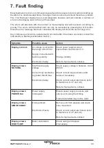
Symptom
Possible cause
Action
Constant 3.8 mA
Error signal set to Low.
Check display for errors
and rectify as above.
Check current output electronics (refer
to Sections 4.6, 4.7 and 4.8).
Constant 22 mA
Error signal set to High. Check display for errors
and rectify as above.
Check current output electronics
(refer to Sections 4.6, 4.7 and 4.8).
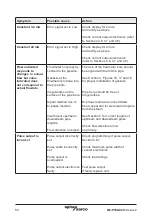
Flow indicated
responds to
changes in
actual
flow but value
indicated does
not correspond to
actual flowrate
Flowmeter not properly
centred in the pipeline.
Gaskets at the
flowmeter protrude into
the pipe bore.
Irregularities on the
surface of the pipe bore.
Signal falsified due to
bi-phase medium.
Insufficient upstream/
downstream pipe
lengths.
Flow direction reversed.
The axis of the flowmeter bore should
be aligned with that of the pipe.
See Section 3, Figures 16, 17 and 18
for proper installation of gaskets.
Pipe bore should be free of
irregularities.
Bi-phase media are not permitted.
Use a separator for wet steam droplets
from the steam.
See Section
3 for correct lengths of
upstream and downstream pipes.
Check flow direction arrow
on primary.
Pulse output is
incorrect
Pulse output incorrectly
set.
Pulse width incorrectly
set.
Pulse output is
overloaded.
Pulse output electronics
faulty.
Check programming of pulse output,
Section 4.6.7.
Check maximum pulse width of
counter electronics.
Check load ratings.
Test pulse output.
If faulty replace unit.


