PulseBlasterESR-PRO
NOTE:
The PulseBlasterESR-PRO requires a 3.3V TTL input signal.
A signal that is more than
3.3V or less than 0V will damage the device
.
Connector Information for 2U BNC Rackmount Enclosure
Connectors for 2U BNC Rackmount Enclosure
This enclosure provides 21 independently controlled output channels through BNC connectors. The
front panel also contains the USB connector, the Trig/Res/Stat DB9 connector, and the ON/OFF toggle
switch which powers on the PulseBlasterESR-PRO-USB-RM. They are arranged in a format which is 3
rows of 8 bits. On the reverse side of the rackmount enclosure is the AC Input.
DB9 Connector (Trig/Res/Stat) for 2U BNC Rackmount Enclosure
The Trig/Res/Stat DB9 connector information is shown in Figure 16 and Table 3, below. The
Hardware Trigger and Hardware Reset are both low-true, so each of these pins would need to be shorted
to ground to cause a trigger or reset, respectively. Please refer to the
and
HW_Trig/Reset Header for SP18A and SP19
, above, for additional information about each pins
functionality.
2019/09/26
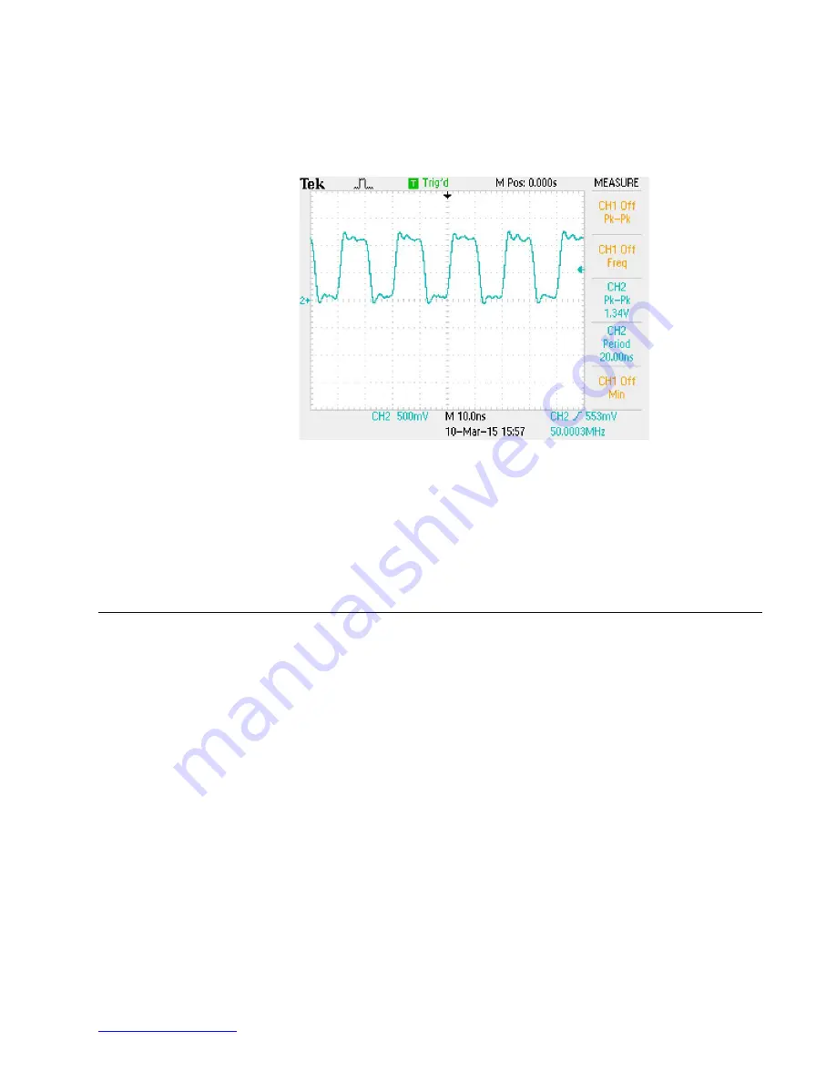
Figure 15:
Example clock signal for SP19. Note that a small degree of
voltage ripple is acceptable, so long as the voltage always remains above
threshold for logical-high signals and below for logical-low signals.


