DXM100 MANUAL
2
118147-001 Rev. D
Remote Programming:
Allows remote programming of
the Output voltage, current, filament limit and preheat level
via the USB, Ethernet or RS232.
X-ray Enable/Interlock:
In local mode,
allows remote
ON/OFF control of the high voltage. In remote mode, the
hardware based dry contact closure must be closed in
order to enable the high voltage via the USB, Ethernet or
RS232.
1.3 System Status and Fault
Diagnostic Display
If a fault occurs, the power supply will revert to the
Shutdown mode indicated by extinguishing of X-ray ON
led and via RS-232 as HV OFF. To reset a fault in local
mode the enable must be reset. To reset a fault in remote
mode a HV ON command must be sent via the RS-232,
USB or Ethernet.
•
OVER CURRENT FAULT:
Indicates the over
current protection circuitry has caused the high
voltage to turn off. This fault will occur if the output
current exceeds 110% of full scale or 110% of current
program value. This fault is indicated by illumination
of over current led status on the front cover and via
RS-232, USB or Ethernet as Over Current.
•
OVERVOLTAGE:
Indicates the over voltage
protection circuitry has caused the high voltage to
turn off. This fault will occur if the output voltage
exceeds 110% of full scale or 110% of program
value. This fault is indicated by over voltage led
status on the front cover and via the RS-232, USB or
Ethernet as Over voltage.
•
ARC FAULT
: Indicates that an arc has occurred.
When a single arc occurs, the high voltage will be
quenched for 150ms and the Arc Fault led will
illuminate for 1 second and be reported via the digital
interface for 1 second as arc fault. If 4 arcs occur
within 10 seconds a HVPS fault will occur and the
HVPS will be shutdown. This fault is indicated by
illumination of Arc Fault led status on front cover and
via RS-232, USB or Ethernet as arc fault.
•
UNDER VOLTAGE:
Indicates a failure in the
voltage regulation circuitry. This fault occurs when
there is a lack of output power to maintain regulation
and will result in shutdown of the HV. This fault will
occur if the output voltage less than 10% below the
program value. This fault is indicated by illumination
of under voltage led status on the front cover and via
RS-232, USB or Ethernet as under voltage.
•
UNDER CURENT:
Indicates failure in the current
regulation circuitry. This fault occurs when the
allowable percentage of error between actual and
programmed emission current is exceeded. This fault
will not cause a shutdown of the HV. This fault will
occur if the output current less than 10% below the
program value. This fault is indicated by illumination
of under current led status on front cover and via RS-
232, USB or Ethernet as under current.
•
OVER TEMPERATURE:
Indicates either a failure
in the cooling system that would cause the internal
heat sink temperature to exceed it’s operating range
or the ambient temperature to exceed 40degC,
resulting in shutdown of HV. This fault is indicated
by over temperature led status on the front cover and
via RS-232, USB or Ethernet as over temperature.
•
Filament Protection:
If the output voltage goes
below 30% of full rating the filament power will be
disable to protect the filament in the users X-ray tube,
but the filament preheat will still be active. This will
cause an undercurrent fault.
•
PS Fault Indication:
PS Faults an open collector
output with a 1k ohm series impedance on J2-1,
indicates that a fault has occurred. High = no faults
•
X-ray On Indication:
X-ray On Signal is an open
collector output a 1k ohm series impedance on J2-14,
indicates X-ray status. High = X-ray Off, Low =X-
ray On
•
X-ray On LED:
when the high voltage status is
“On” state it is indicated by X-RAY ON led status on
the front cover
•
Power On LED:
when the input power is applied to
the unit it is indicated by PWR ON led status on the
front cover
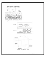
1.4 Interpreting the Model Number:
The model number of the power supply describes its
capabilities. After the series name is:
(1)
The maximum voltage in kilovolts.
(2)
The polarity of the output – positive (P), or
negative (N).
(3)
The maximum output in watts.
(4)
Custom “X” number representing details listed in
a separate specification control drawing.
Summary of Contents for DXM100 Series
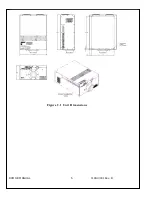
Page 11: ...DXM100 MANUAL 5 118147 001 Rev D Figure 2 1 Unit Dimensions ...
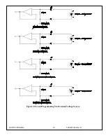
Page 16: ...DXM100 MANUAL 10 118147 001 Rev D Figure 3 3 Local Programming Via External Voltage Source ...
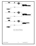
Page 17: ...DXM100 MANUAL 11 118147 001 Rev D Figure 3 4 Remote Monitoring ...
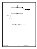
Page 18: ...DXM100 MANUAL 12 118147 001 Rev D RELAY Figure 3 5 Enable Interlock Logic Control ...
Page 37: ...118142 001 Rev B Page 13 of 104 Figure 9 Web Page 1 Contact Information ...


