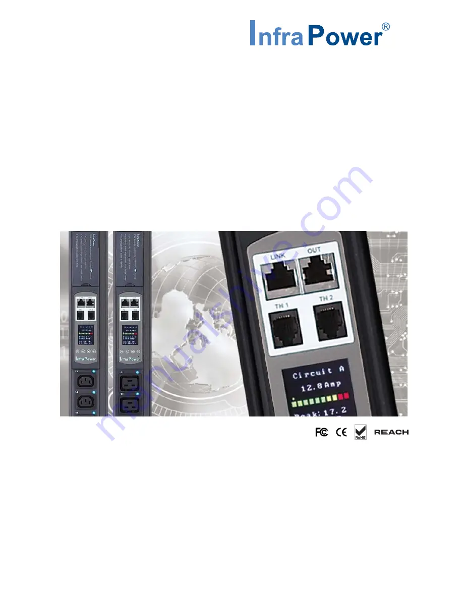
background image

www.austin-hughes.com

UM-IPM-02-Q414V3

IPM-02

  PDU management software

W

 kWh Monitored PDU

WS

 kWh Switched PDU

PDU Inspired by Your Data Center

User Manual

Designed and manufactured by Austin Hughes

Summary of Contents for IPM-02

Page 1: ...www austin hughes com UM IPM 02 Q414V3 IPM 02 PDU management software W kWh Monitored PDU WS kWh Switched PDU PDU Inspired by Your Data Center User Manual Designed and manufactured by Austin Hughes ...

Page 2: ...ce personnel should open the chassis Opening it yourself could damage the equipment and invali date its warranty If any part of the equipment becomes damaged or stops functioning have it checked by qualified service personnel What the warranty does not cover Any product on which the serial number has been defaced modified or removed Damage deterioration or malfunction resulting from Accident misus...

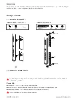
Page 3: ...ut M6 nut Bracket x 2 2 Rackmount W WS PDU x 1 OR Power ON Connect the PDU into an appropriately rated receptacle When the PDU is power on the LED display will light up That means all outlets are activated Keep the equipments in the power off position until it is plugged into the PDU Don t exceed the outlet branch or phase limitations All electrical power and power control wiring must be installed...

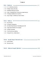
Page 4: ...allation Connection 1 6 Easy Change on PDU Power Feed Position Part II Software 2 1 Key Features 2 2 IP Dongle Configuration 2 3 Hardware Requirements of the Management PC 2 4 Supported OS Platform Language 2 5 Software Download 2 6 First Time Start up Setting 2 7 Change Port no of Web Server Part III System Setup Remote Access 3 1 System Setup 3 2 Remote Access Part IV Software Usage Operation P ...

Page 5: ...www austin hughes com UM IPM 02 Q414V3 Content Part V Events Log Report Part VI SNMP Setup Firmware Upgrade Part VII FAQ Part VIII Troubleshooting P 30 P 33 P 37 P 40 ...

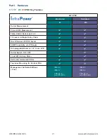
Page 6: ...ingle Daisy Chain One IP Access 16 PDU Levels SNMP Capability via IP Dongle Hot pluggable Meter w 1 8 Color LCD Outlet Switch ON OFF Local kWh Amp Meter Vertical Horizontal PDUs Tool less Mounting for Vertical PDU Management Software Editions Free IPM 03 IPM 02 PPS 02 S via IPD 02S IPM 03 IPM 02 PPS 02 S via IPD 02S Part I Hardware 1 1 W WS PDU Key Features ...

Page 7: ... will not affect any settings and memories 5 3 4 1 PDU cascade port 1 2 All W series PDUs are equipped with a highly advanced and sophisticated component W Meter It provides the cascade ports for daisy chain up to 16 x PDU Furthermore for IP PDU access simply connect 1 x IP Dongle for all daisy chain PDUs to save IP network address Two sensor ports are integrated for temperature humidity monitorin...

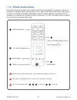
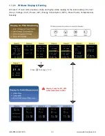
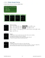
Page 8: ...Si outlet measurement PDU Press to change C F Display 1 1 W meter 1 8 color LCD provides a sharp and highly visible reading for the local reading of Current Amp Voltage Volt Power kW Energy Consumption kWh Power Factor Temperature Humidity 1 2 W Meter Display Setting ...

Page 9: ... allows the user to set the meter buzzer ON OFF by meter s 4 buttons All PDUs are shipped with the buzzer in ON status When the PDU s circuit Amp is over alarm level the buzzer will sound The user can press any button to stop the buzzer sound Screen OFF All PDUs are shipped with the metter LCD in always ON status W meter allows the user to turn off the meter LCD by time setting 1 60 mins 0 always ...

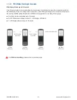
Page 10: ... the local power monitoring but also the connection ports for the PDU daisy chain For daisy chain connection each PDU just simply to be connected in series to the next by Cat5 6 cables Maximum 16 PDUs are supported in one daisy chain group 1st level PDU meter Final level PDU meter 3rd level PDU meter 2nd level PDU meter Cat 5 6 cable Up to 20M Cat 5 6 cable Up to 20M For PDU level setting please r...

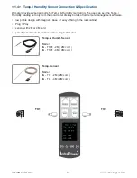
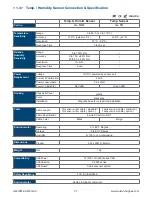
Page 11: ...s 2 sensor ports for Temp Humidity monitoring The user can see the Temp Humidity reading not only from the local meter display but also from remote management software low profile design with magnetic base for easy affixing to the rack cabinet Plug n Play sensor with 2M or 4M cord pair of sensors can be connected to a single W meter 1 4 Temp Humidity Sensor Connection Specification ...

Page 12: ...Power consumption 0 24 Watt Power on indicator Red LED Green LED Housing Chassis Cover plastic Color Dark gray Installation Magnetic base for unrestricted installation Cable Cable Length TH sensor w 2m cable standard TH sensor w 4m cable option T sensor w 2m cable standard T sensor w 4m cable option Cable Specification 4 wired 3 5mm to RJ11 Cable Color Black Beige Environmental Operating 0 to 80 C...

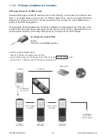
Page 13: ... port IP Dongle Access to 16 PDU Levels Patented IP Dongle provides IP remote access to the PDUs by a true network IP address chain Only 1 x IP dongle allows access to max 16 PDUs in daisy chain which is a highly efficient ap plication for saving not only the IP remote accessories cost but also the true IP addresses re quired on the PDU management Hot Pluggable design facilitates the IP dongle ins...

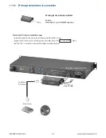
Page 14: ...s plug the RJ 45 connector of IP dongle into the LINK port of the 1st level PDU meter use the CAT 5 6 cable to connect IP dongle to network device 1 5 IP dongle installation connection IP dongle for rackmount PDU Model IPD H02 S with SNMP feature To LINK port of the 1st PDU Rear side of rackmount PDU IP dongle To LAN port of IP dongle Network Hub ...

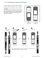
Page 15: ...ibility to simply turnover on top feed PDUs with the use of meter inversion buttons and an alternative membrane B A B A B A Press first button last button to invert display Replace the meter membrane Completed Membrane A Membrane A Membrane B Turn the PDU upside down 1 3 2 4 Please take the reverse steps to change top feed to bottom feed entry Outlet no stickers are provided on request Meter Membr...

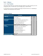
Page 16: ...ter operation Part II Software Features Capacity IP Dongle Group Just 1 for 16 PDU levels 15 PDU number 240 Concurrent Users 5 Enhanced Features Energy Consumption kWh Monitoring Apparent Power kVA Monitoring Power Factor Measurement Circuit Breaker Monitoring SNMP Capability via IP Dongle Basic Features Aggregate Current Amp Monitoring Individual Outlet Switch ON OFF Temp Humid Monitoring Alarm T...

Page 17: ...to configure the IP dongle IP dongle on 1st level PDU To IP dongle LAN port To notebook computer LAN port CAT 5 6 cable Step 4 Click Scan to search the connected IP dongle Step 5 Enter device name in Name min 4 char max 16 char Default is Name Step 6 Enter device location in Location min 4 char max 16 char Default is Rack_001 Step 7 Enter password in Password for authentication min 8 char max 16 c...

Page 18: ... the OS platforms languages as below MS Windows XP Professional with SP3 32bit only MS Windows 7 Professional with SP1 MS Windows 7 Ultimate with SP1 MS Windows Server 2003 R2 Standard Edition with SP2 MS Windows Server 2008 Standard Edition SP2 MS Windows Server 2008 R2 Standard Edition SP1 Ensure the user logins in the management PC as a member of Administrators Group before IPM 02 Installation ...

Page 19: ...ager IPM 02 can support max 5 concurrent login users and manage multi IP don gles max 15 hence the concurrent login users can access remote PDUs max 240 15 IP dongles x 16 level PDUs Software download Please download the free InfraPower Manager IPM 02 to the management PC from the link http www austin hughes com support software infrapower IPM 02 msi IPM 02 msi Double click the IPM 02 msi and foll...

Page 20: ...setting IPM 02 InfraPower Manager 2 6 First Time Start up Setting For MS Windows 7 and MS Windows server 2008 it requires to run a program with administrator rights before execution Right click InfraPower Manager IPM 02 and then select Properties Click the Compatibility tab Tick the box Run this program as an administrator and then click OK ...

Page 21: ...e appropriate no here and follow the instruction in Change port no of web server next page to make the change effective PostgreSQL password can be changed by user The password MUST contain at least three of the following four character groups English uppercase characters A through Z English lowercase characters a through z Numerals 0 through 9 Non alphabetic characters such as 2 6 First Time Start...

Page 22: ...tart up setting is completed Step 1 Go to the path of web server being installed Default C AppServ Apache2 2 conf Step 2 Open httpd conf change Listen 80 to Listen xx where xx means the port users want to use save the change Step 3 Restart Apache services Go to Control Panel Administrative Tools Services Apache2 2 Click Restart Complete Step 4 Refresh the Web browser 2 7 Change Port no of Web Serv...

Page 23: ...3 Enter User name Default is admin Enter Password Default is 00000000 Users can follow below step 1 3 to access the management PC and InfraPower Manager IPM 02 Then users should go to User Setup Alarm General Backup for initial system setup Only Administrator is authorised to access User Setup Alarm General Backup Login user Router or hub 1 2 3 4 5 Login user Login user Login user Login user Manag...

Page 24: ... can create 4 more operators Step 1 Tick Operator 1 Step 2 Input User name User login password Step 3 Input user login password in Confirm password again Step 4 Repeat Step 1 to 3 for other operators if necessary Step 5 Click Apply to save the user setup 3 1 System setup ...

Page 25: ... IP dongle group 01 Step 2 Input IP address password of the IP dongle Step 3 Enable Command password Step 4 Input New command password Default is 00000000 Step 5 Input new command password in Confirm new password again Step 6 Click Apply to finish the IP dongle group setup Step 7 Repeat step 1 to 6 for other IP dongle groups if necessary 3 1 System setup ...

Page 26: ... Step 2 Input SMTP server and SMTP port Step 3 Input User email Step 4 Enable or Disable the SMTP authentication Step 5 Input User name and Password Step 6 Select the SMTP secure None SSL TLS Step 7 Input the Alarm interval Step 8 Input the alarm recipient email account in Alarm mail recipient 01 Step 9 Repeat step 8 for other alarm recipients if necessary Step 10 Click Apply to finish the alarm e...

Page 27: ...P 22 In Backup administrator can Enable or Disable the daily data backup When Enable the backup path can be changed In General administrator can change the Refresh rate Scan rate Temperature unit across all IP dongle groups 3 1 System setup ...

Page 28: ...www austin hughes com UM IPM 02 Q414V3 P 23 Sys log provides past 2000 event records of User Setup Alarm General Backup 3 1 System setup ...

Page 29: ...d Rules select New Rule Select Port Click Next Select TCP then All local ports Click Next Select Allow the connection Click Next Tick all three options Click Next Input the Name Description of the port Click Finish Step 2 Open the web browser of remote client PC Step 3 Input the URL of InfraPower Manager IPM 02 in the address bar e g http 192 168 0 1 IPM 02 If the port no of web server is not 80 p...

Page 30: ...Us in each IP dongle group The real time clock of the PDUs will be synchronized from the management PC during searching process If search fails please refer to P 35 for IP dongle firmware upgrade Scan function to monitor the PDUs status of each IP dongle group ONE by ONE Part IV Software Usage Operation ...

Page 31: ...Change Alarm amp Rising alert amp Low alert amp of PDU s circuits Click Apply Click Reset to reset peak amp or kWh of PDU s circuits Click ON OFF to swich ON OFF outlet WS kWh Switched PDU only View On Off status of each PDU s outlet View aggregated current on the PDU Part IV Software Usage Operation ...

Page 32: ...es com UM IPM 02 Q414V3 P 27 In Outlet setting Change PDU s outlet name Change Power up sequence delay of PDU s outlet WS kWh Switched PDU only Click Apply to finish the above settings Part IV Software Usage Operation ...

Page 33: ...Q414V3 P 28 In TH status View status location lastest reading alarm setting of Temp Humid sensors connected to each PDU The GUI does not show the readings if the TH sensors are not installed activated Part IV Software Usage Operation ...

Page 34: ...Location Rising alert Setting Alarm Setting of Temp Humid sensors Click Apply to finish the above settings The default TH setting is Deactivate When install T or TH sensor please tick Activate Otherwise no readings display DON T activate T or TH sensor if no sensor installed Part IV Software Usage Operation ...

Page 35: ...t 2000 event records of PDUs configuration connection outlet configuration sensors configuration connection in an IP dongle group PDU log provides past 2000 log records of each PDU The software will generate a PDU log record every 10 mins Part V Events Log Report ...

Page 36: ... will generate a TH log record every 10 mins Daily kWh log provides past 2000 daily energy consumption log records of each PDU The record is logged at 00 00 everyday 5 mins for previous day The daily kWh log will not be recorded at 00 00 if the PDU connected less than 24 hours Complete Part V Events Log Report ...

Page 37: ...V format Please follow the steps below to export the log category you want Step 1 Select Category Period Target Step 2 Click Apply Click OK from the pop up window Step 3 Right Click the file name below Select Save target as to download the log file Step 4 Click Close to complete or Open to view the content of log file Complete Part V Events Log Report ...

Page 38: ... file at this URL http www austin hughes com support utilities infrapower IPD MIB mib II Enabling SNMP Support The following procedure summarizes how to enable the IP Dongle for SNMP support Step 1 Connect the IP dongle to a computer Please refer to P 12 Step 2 Open the Internet Explorer I E version 8 0 or above Step 3 Enter the configured IP dongle address into the I E address bar Default IP addr...

Page 39: ...le in SNMP Agent to start the SNMP agent service Step 8 Input Read Community Default is public Step 9 Input Write Community Default is private Step 10 Select disabled or V2Trap in SNMP Traps If select V2Trap please input IP address of the SNMP management station in Station IP Step 11 Click Apply to finish the SNMP settings Part VI SNMP Setup Firmware Upgrade ...

Page 40: ...irmware from the link http www austin hughes com support software infrapower V2395S img Step 2 Connect the IP dongle to the computer Step 3 Open the Internet Explorer I E version 8 0 or above Step 4 Enter the configured IP dongle address into the I E address bar Default IP address is 192 168 0 1 Step 5 Enter Login name Password Default login name password are 00000000 Step 6 Select the Firmware fr...

Page 41: ...rmware upgrade window appears as below Step 8 Click Browse and select the firmware file xxx img from the specific path in the pop up window and Click Open Step 9 Click Upgrade to start the upgrade process It takes a few minutes to complete Step 10 Once complete UI will return to the login page ...

Page 42: ...ore IPM 02 Installation and execution 3 Why user can t login to the Management PC remotely Make sure the port for web server is added in the firewall setting and the services of web server is started in the management PC 4 Which database does the IPM 02 support PostgreSQL 5 What is the PostgreSQL default password for IPM 02 1qaz2WSX 6 How can I receive alarm email and get full log report Ensure th...

Page 43: ... the IP dongle support DHCP Dynamic Host Configuration Protocol No the IP dongle only works with static IP address 4 Will the reset of IP dongle affect the power to the outlets No the IP dongle operates on a separate circuit so the power to the outlets will remain unchanged 5 How can I replace a failed IP dongle As the IP dongle is hot swappable without power disconnection you can unplug the RJ45 ...

Page 44: ...model PDUs can connect together as a cascade chain 4 If one of the cascaded WS kWh switched W kWh Monitored PDU loses power will it affect other PDUs in the same chain No the other cascaded WS kWh switched W kWh Monitored PDUs in upper lower level will not be affected 5 What is the maximum cabling distance between two cascaded PDUs Up to 20 meter 66 feet of CAT 5 6 cable 6 What is the maximum casc...

Page 45: ...hen plug it to the second disconnected PDU to check if the problem caused by the first disconnected PDU 3 GUI shows the whole group of PDU s disconnected Step 1 Cable disconnected loose or defective Check the Cat 5 6 cable connection to PDUs and network devices Make sure the connectors are firmly attached And check if any defects on your cable or not If yes replace a new one Step 2 IP dongle faile...

Page 46: ... new PDU and connect to the device s Step 8 Click Start Connection in Status page for the relevant IP dongle Step 9 Configure the new PDU in Details and TH Sensor page such as Alarm Amp Name Location Step 10 Enable alarm email in Alarm page 3 How to replace a failed certain level PDU with a new one Step 1 Prepare a new PDU and set the PDU level accordingly Please refer to user manual 1 2 display 9...

Page 47: ...s in the last level 5 How to add an extra PDU to an existing PDU group Step 1 Prepare a PDU and set the PDU level accordingly Please refer to 1 2 display 9 1 for the PDU level setting Step 2 Prepare an appropriate length Cat 5 6 cable Step 3 Click Set maintenance in Details page for the affected PDU s which next to the added PDU Step 4 Install and connect the new PDU Step 5 Power on the new PDU St...

Page 48: ... service Check if the port for web server is used by other service If yes please release the port of that particular service and assign another port for it Step 3 Port for web server is added in the firewall of management PC Check if the port is added in the firewall If not please add and enable the connec tion in the firewall Please refer to user manual 3 2 for details 1 8 meter LCD display 1 LCD...

Reviews: