118142-001 Rev B
Page 16 of 104
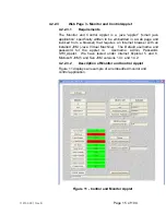
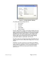
Broadly one can view the screen as a “left” and a “right” with
the left half containing status values (read backs) read from
the DXM100 and the right half containing the values that are
configurable by the user. Notice that the top of the right half
contains the label “Click to Set”. For any configurable setting
you click on the button to the left of the setting, which brings
up the program set point screen. For example, click on the
button labeled, ‘V’ to set the output voltage set point. Refer
to figure 12.
4.2.2.4
Program Set Point Screen
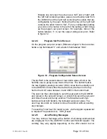
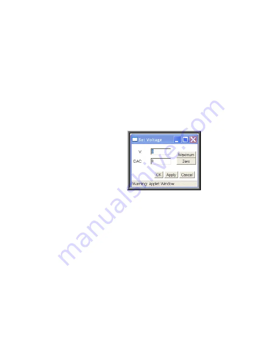
On the program set point screen (Reference figure 12 there are two
fields: a top field labeld ‘V’ and a bottom field labeled ‘DAC’.
Figure 12 - Program Configurable Values Screen
The top field is the scaled value or real world value, which is the
field the user is going to use most of the time. The bottom field is
the raw digital-to-analog converter (DAC) value that is actually sent
to the DXM100. Enter either the desired set point level in the top
field or the DAC value between 0 and 4095 in the bottom field.
The user can then click Apply to send the set point to the DXM100
and remain in the set point screen, or click OK to send the set point
and close the set point entry window. The Maximum and Zero
buttons will set both fields to the indicated end point value. The
user may also click on Cancel to close the window without sending
any changes.
To reset the Total hour On meter to zero via the Applet a password
is required.The password is “SHV_Reset”
4.2.2.5
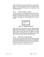
Java Warning Messages
You may notice a message at the bottom of all dialog windows that
are displayed from the DXM100 Control and Monitor Applet. The
wording may vary slightly depending on the JVM version but on
Summary of Contents for DXM100 Series
Page 11: ...DXM100 MANUAL 5 118147 001 Rev D Figure 2 1 Unit Dimensions ...
Page 16: ...DXM100 MANUAL 10 118147 001 Rev D Figure 3 3 Local Programming Via External Voltage Source ...
Page 17: ...DXM100 MANUAL 11 118147 001 Rev D Figure 3 4 Remote Monitoring ...
Page 18: ...DXM100 MANUAL 12 118147 001 Rev D RELAY Figure 3 5 Enable Interlock Logic Control ...
Page 37: ...118142 001 Rev B Page 13 of 104 Figure 9 Web Page 1 Contact Information ...


