background image

Spectralink DECT Server 8000 Installation Guide

14184630 Version 8.0, K016
September, 2015

6

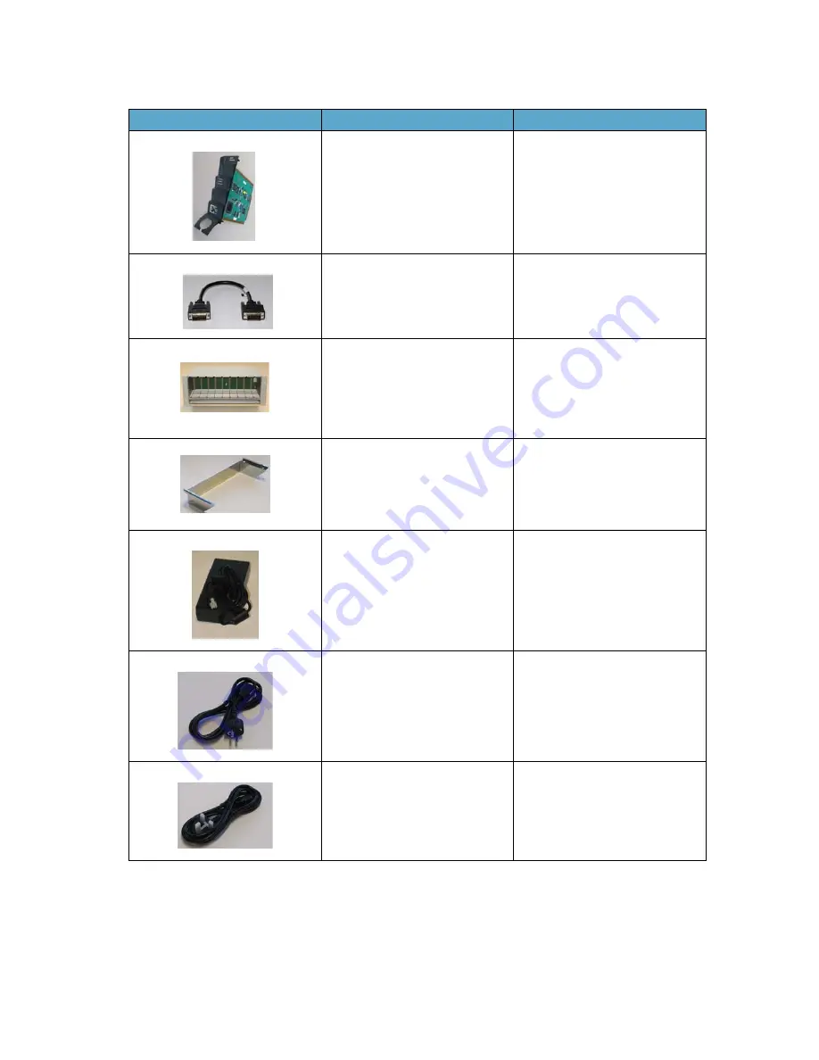
Media Resource Card

0233 9700

Link cable

0233 9400

EU rack

US rack

UK rack

0233 8900

0233 8901

0233 8902

Includes mains adapter and mains 
cable.

Wall hanger

0250 0200

Mains adaptor

8476 9902

EU mains cable

8468 7013

UK mains cable

8468 7014

Table 5

DECT Server 8000 Components

Picture

Description

Part Numbers

Summary of Contents for DECT Server 8000

Page 1: ...Spectralink DECT Server 8000 Installation Guide 14184630 version 8 0 K016 September 2015 ...

Page 2: ...ct identification copyright or other notices Notice Spectralink Corporation has prepared this document for use by Spectralink personnel and customers The drawings and specifications contained herein are the property of Spectralink and shall be neither reproduced in whole or in part without the prior written approval of Spectralink nor be implied to grant any license to make use or sell equipment m...

Page 3: ...Replacing Components 20 Component Replacement 20 Component Replacement Precautions 20 To Replace an Interface Card 20 To Replace or Install a New CPU Card 21 Replacing the Backplane 21 To Replace an AC Adapter 21 Regulatory Notices 22 International Regulatory and Product Information 22 United States Federal Communication Commission FCC 22 United States Safety Construction Details 22 CE Mark R TTE ...

Page 4: ... 0 K016 September 2015 2 Spectralink DECT Server 8000 Installation Guide Analogue Interface Card 33 Base Station Interface Card for 4 channels Base Stations 33 Base Station Interface Card for 8 channels Base Stations 34 ...

Page 5: ...r 8000 on a stable flat surface in the selected location and inspect the package for any damage and report it to the reseller or distributor immediately Specifications Important Make sure only authorized persons have access to the equipment Please review all the safety instructions for important safety and regulatory information The DECT Server 8000 rack can only be installed in a Restricted Acces...

Page 6: ...tion Power consumption Typical AC Power Consumption 90 Watt Max AC Power Consumption Max 360 Watt Table 4 Environment Environment Operating temperature 0 C 40 C 22 104 F Storage temperature 30 C 70 C 40 158 F Relative humidity 20 80 Non condensing Operating altitude Up to 2000 m 6 500 ft Operating ESD level 4 KV ...

Page 7: ... DECT Server 8000 parts and their part numbers Table 5 DECT Server 8000 Components Picture Description Part Numbers Base Station Interface card 8 base stations 0233 9100 Analogue Interface card 16 lines 0233 9200 Analogue Interface card 8 lines 0233 9220 CPU card with link option 0233 9800 Includes two terminator connectors CPU card without link option 0233 9900 ...

Page 8: ...source Card 0233 9700 Link cable 0233 9400 EU rack US rack UK rack 0233 8900 0233 8901 0233 8902 Includes mains adapter and mains cable Wall hanger 0250 0200 Mains adaptor 8476 9902 EU mains cable 8468 7013 UK mains cable 8468 7014 Table 5 DECT Server 8000 Components Picture Description Part Numbers ...

Page 9: ... it can be used as an alternative to the RS232 connection US mains cable 8468 7015 Terminator connector 0250 0300 RS232 cable 13281100 Note Link connections must not be left open You must either plug in a link cable or a terminator connector for protection and for stable functionality Table 5 DECT Server 8000 Components Picture Description Part Numbers Link upwards Link downwards USB Ethernet RS23...

Page 10: ...ctions for AB Lines Figure 4 Media Resource Card Connection General Installation Information The maximum number of DECT Server 8000 units that can be linked together depends on the mounting method and the maximum length of the link cable A RJ45 Connection B RJ45 Connection A RJ45 Connection B RJ45 Connection D RJ45 Connection C RJ45 Connection A Ethernet ...

Page 11: ...pment To minimize risk to service personnel and users the system must be connected to an outlet with a third wire earth connection Ensure that the leveling jacks on the bottom of the rack are fully extended to the floor with the full weight of the rack resting on them In a single rack installation stabilizers should be attached to the rack In multiple rack installations the racks should be coupled...

Page 12: ...ntilation always leave 2 3 U between the Spectralink DECT Server 8000Spectralink DECT Server 8000 units any other units mounted in the rack To Install the Spectralink DECT Server 8000 in a Rack You can install the Spectralink DECT Server 8000 in a rack using one of the two following methods 1 Install the brackets supplied by the rack manufacturer on each side of the rack on which the Spectralink D...

Page 13: ...efore placing the unit carefully turn it upside down and mount the four rubber pads supplied in the package One must be placed at each corner of the bottom plate 3 Place it on a clean flat horizontal surface Installing the Spectralink DECT Server 8000 on a Wall Before you start installation take notice of the following safety precautions Wall Mounting Safety Precautions Ensure the wall quality is ...

Page 14: ...olts or other appropriate fastening methods in relation to the wall material Remove any drilling dust 3 Fit the DECT Server 8000 into the wall hanger and fasten the two front screws Figure 7 Fitting the Spectralink DECT Server 8000 into the wall hanger Connecting the Spectralink DECT Server 8000 Cables When the Spectralink DECT Server 8000 has been mounted the cables can be connected DECT Server 8...

Page 15: ...ables The interface cables must be removed before any interface card is removed or replaced When unplugging power unplug AC mains power first before unplugging the power connector from the Spectralink DECT Server 8000 The AC adapters must never be hanging by their own weight in the AC mains connector or the output connector To Connect Power Cables The Spectralink DECT Server 8000 has four power pl...

Page 16: ... 32ºCelcius 89 6º Fahrenheit and they have free air surrounding them Installing Interface Cards and CPU Cards Before you install an interface or a CPU card ensure to take the following precautions Safety Precautions Cards contain static sensitive circuitry and may be destroyed or damaged by electrostatic discharge ESD Make sure you re using proper ESD equipment to prevent damage to the system Fill...

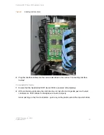
Page 17: ... in the section Conntecting Interface Cables To Install CPU Cards 1 Ensure that the Spectralink DECT Server 8000 is powered off completely 2 With two hands gently slide the card into the unit Give the card a gentle push on the last centimeter so that it enters the backplane connector properly Avoid pushing on the front connectors push only on the plastic parts at the top and bottom ...

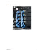
Page 18: ...insert terminator connectors 5 Connect the Spectralink DECT Server 8000 to a PC using theRS232 cable 6 Connect the power and reboot the unit Connecting Interface Cables The front interface of the Spectralink DECT Server 8000 is provided with connectors for the different interfaces provided Please see the Spectralink DECT Server 8000 Configuration Guide for the actual pin out of the different conne...

Page 19: ...Spectralink DECT Server 8000 Installation Guide 14184630 Version 8 0 K016 September 2015 17 Figure 11 Harnessing cables to the back and out ...

Page 20: ...e 14184630 Version 8 0 K016 September 2015 18 Figure 12 Harnessing cables to the side and out Regardless of which way is used for harnessing you must guide the cables through the opening in the plastic front This ensures safe retention of the cable ...

Page 21: ...sion 8 0 K016 September 2015 19 Connecting the Link Cable In installations where 2 or more Spectralink DECT Server 8000 units are linked together it is important that the link cable is plugged into the proper port Figure 13 Link Cable Link upwards Link downwards ...

Page 22: ...rge ESD All maintenance tasks must be performed by qualified authorized personnel only Use only original replacement parts Make sure you are using proper ESD equipment to prevent damage to the system Fill all empty slots with blanking front plates to close the front To Replace an Interface Card 1 Ensure the Spectralink DECT Server 8000 unit is properly earthed 2 Unplug all interface cables on the ...

Page 23: ...s the backplane connector properly Avoid pushing on the front connectors push only on the plastic parts at the top and bottom 7 Plug the interface cables into the card 8 Connect power and reboot the unit Replacing the Backplane The backplane cannot be replaced on site The rack will have to be returned for repair or be replaced with a new one If a new rack is to be installed you can move the cards ...

Page 24: ...d to correct the interference at his or her own expense United States Safety Construction Details All connections are indoor only No direct connections to public networks Unit is intended for RESTRICTED ACCESS LOCATION Unit is to be installed in accordance with the National Electrical Code The branch circuit overcurrent protection shall be rated 20 A for the AC system This equipment has a maximum ...

Page 25: ...ons of the power utility telephone lines and internal metallic water pipe system if present are connected together This precaution may be particularly important in rural areas Caution Users should not attempt to make such connections themselves but should contact the appropriate electric inspection authority or electrician as appropriate Important Safety Instructions and Product Information Before...

Page 26: ...n dropped or cabinet has been damaged If the product exhibits a distinct change in performance Warning 1 Avoid using telephone during an electrical storm There may be a risk of electrical shock from lightning 2 Do not use the telephone to report a gas leak in the vicinity of the leak 3 Do not place the unit near microwave ovens radio equipment or non ground connected televisions These appliances m...

Page 27: ...ternet or otherwise the Software is licensed not sold Customer shall not reverse compile disassemble or otherwise reverse engineer embed within any other software product or modify in any manner with respect thereto the Software in whole or in part THE TERMS AND CONDITIONS APPLICABLE TO Spectralink S LIMITED WARRANTY ARE AS SET FORTH BELOW AND ARE ALSO INCLUDED IN THE DOCUMENTATION PACKAGED WITH N...

Page 28: ...MPLIED EITHER IN FACT OR BY OPERATION OF LAW STATUTORY OR OTHERWISE INCLUDING WARRANTIES TERMS OR CONDITIONS OF MERCHANTABILITY FITNESS FOR A PARTICULAR PURPOSE SATISFACTORY QUALITY CORRESPONDENCE WITH DESCRIPTION AND NON INFRINGEMENT ALL OF WHICH ARE EXPRESSLY DISCLAIMED SPECTRALINK NEITHER ASSUMES NOR AUTHORIZES ANY OTHER PERSON TO ASSUME FOR IT ANY OTHER LIABILITY IN CONNECTION WITH THE SALE IN...

Page 29: ...y SPECTRALINK B V in Europe the Middle East Africa and Asia Pacific or the SPECTRALINK SOFTWARE PRODUCT licensed by SPECTRALINK Inc in the rest of the world collectively referred to herein as SPECTRALINK The SOFTWARE PRODUCT includes computer software as attached hereto and may include associated media printed materials and online or electronic documentation SOFTWARE PRODUCT By clicking I agree or...

Page 30: ...e any transfer must include all prior versions of the SOFTWARE PRODUCT However if the SOFTWARE PRODUCT is marked Not for Resale or NFR you may not resell it or otherwise transfer it for value 2 6 Copyright All title and copyrights in and to the SOFTWARE PRODUCT including but not limited to any images photographs animations video audio music text and applets incorporated into the SOFTWARE PRODUCT t...

Page 31: ...use on more than one PRODUCT 6 WARRANTY AND WARRANTY EXCLUSIONS 6 1 Limited Warranty SPECTRALINK warrants that a the SOFTWARE PRODUCT will perform substantially in accordance with the accompanying documentation for a period of ninety 90 days from the date of receipt by you and b any SUPPORT SERVICES provided by SPECTRALINK shall be substantially as described in applicable written materials provide...

Page 32: ...OWEVER IF YOU HAVE ENTERED INTO A SPECTRALINK SUPPORT SERVICES AGREEMENT SPECTRALINK S ENTIRE LIABILITY REGARDING SUPPORT SERVICES SHALL BE GOVERNED BY THE TERMS OF THAT AGREEMENT 8 DISCLAIMER Some countries states or provinces do not allow the exclusion or limitation of implied warranties or the limitation of incidental or consequential damages for certain products supplied to consumers or the li...

Page 33: ...sire to contact SPECTRALINK for any reason please contact the SPECTRALINK office serving your country 10 4 U S Government Restricted Rights The SOFTWARE PRODUCT and documentation are provided with RESTRICTED RIGHTS The SOFTWARE PRODUCT programs and documentation are deemed to be commercial computer software and commercial computer software documentation respectively pursuant to DFAR Section 227 72...

Page 34: ...lowing table shows the assignments of wire pairs to plug and socket pins of the RJ45 cable Table 1 RJ45 cable wiring Pin Pair Wiring Connector A Connector B Connector C Connector D 1 2 tip 1 5 9 13 2 2 ring 1 5 9 13 3 3 tip 2 6 10 14 4 1 ring 0 4 8 12 5 1 tip 0 4 8 12 6 3 ring 2 6 10 14 7 4 tip 3 7 11 15 8 4 ring 3 7 11 15 ...

Page 35: ...erface Card for 4 channels Base Stations Note Previous version of Digital Base Station was connected using RJ11 at the Base Station The new version of the Digital Base Station are using RJ45 at the Base Station RJ45 to the Spectralink DECT Server 8000 Clip facing DOWN Extensions from the PBX RJ45 to the Spectralink DECT Server 8000 Clip facing DOWN Base Station ...

Page 36: ...Interface Card for 8 channels Base Stations To use all 8 Channels in the Base Station connection must be done as below RJ45 Pins Figure 1 RJ45 Pin Position Note 4 8 channels Base Stations can be mixed in the set up 8 channels needs to be connected to the same RJ45 socket on the Base Station Interface Card ...

Page 37: ...er 8000 Installation Guide 14184630 Version 8 0 K016 September 2015 35 Tables Physical Dimensions 3 Power Supply 3 Power Consumption 4 Environment 4 DECT Server 8000 Components 5 Cable Plugs Overview 14 RJ45 cable wiring 32 ...

Page 38: ...Resource Card Connection 8 Figure 5 Rack Installation 10 Figure 6 Wall hanger positioning 12 Figure 7 Fitting the Spectralink DECT Server 8000 into the wall hanger 12 Figure 8 DECT Server 8000 Power plugs 13 Figure 9 Installing Interface Cards 15 Figure 10 Installing CPU card 16 Figure 11 Harnessing cables to the back and out 17 Figure 12 Harnessing cables to the side and out 18 Figure 13 Link Cab...

Page 39: ...Spectralink DECT Server 8000 Installation Guide 14184630 Version 8 0 K016 September 2015 37 ...

Page 40: ......

Page 41: ......

Page 42: ...14184630 Version 8 0 K016 Rasmussens Bogtrykkeri Ringkøbing ...

Reviews: