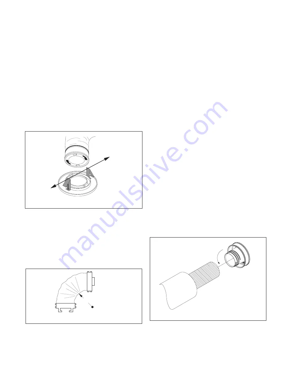
NOTICE: Do not shorten sound attenuating tube
length. The result would be unacceptable noise.
Push the free end of the sound attenuating tube through
the 4" hole until the two toggle springs on the room
terminator snap into place.
Center the two spring clips on a line parallel to the direc-
tion of the tubing routing from the room terminator (see
Figure 2.16). This is important since the weight of the
tubing will have a tendency to cause a part of the termi-
nator to pull away from the ceiling if the clips do not run
parallel to the tubing run.
Then tighten the screws (attached to the terminator) until
the terminator is snug against the ceiling or floor.
Do not
overtighten.
For installations with floors or ceilings
which are thicker than normal, field supplied longer
toggle screws or special mounting plates may be
required.
13
4" MINIMUM RADIUS
FIGURE 2.17: MINIMUM TUBING BEND
TUBING ROUTING
FIGURE 2.16: POSITIONING ROOM TERMINATOR
Supply Tubing Installation
Kwik-connects and balancing orifices are provided in the
Installation Kits. Plenum take-offs, gaskets and fasteners
are supplied in the separate plenum take-off kit.
Avoid sharp bends in the supply tubing (as well as the
sound attenuating tubing). The minimum radius bend is
4" (see Figure 2.17); however, wherever possible, hold to
a larger radius.
TWIST
FIGURE 2.18: KWIK-CONNECT INSTALLATION
At the plenum, all supply tubing connections must be a
minimum of 18" from any plenum tee, plenum elbow or
the fan coil unit.
Individual supply tubing runs must be a minimum of
6-feet, even if the distance between the sound attenuat-
ing tubing and plenum is less than 6 feet.
Supply tubing comes in 100-foot sections (R8 tubing
comes in 50-foot sections and R6 tubing comes in 75-
foot sections) and may be cut to length with a knife or fine
tooth hacksaw.
For each supply tubing run, estimate and cut the length
of tubing that will be needed between the plenum and
sound attenuating tube. At the open end of the supply
tubing a kwik-connect will be installed (see Figure 2.18).
First, push back the cover and the insulation exposing
approximately 4" of the inner core. Fold in any tails or
frays that may be present after cutting the supply tubing.
Second, hand compress the corrugations until they are
densely compacted 1
1
⁄
2
" to 2" from the open end of the
supply tube. Third, thread kwik-connect into the inner
core until snug. Fourth, pull the insulation and cover for-
ward and tuck it into the deep groove on the back side of
the kwik-connect. Fifth, wrap the connection securely
with UL181 approved tape.
When finished, simply twist together (see Figure 2.19)
the kwik-connect on the sound attenuating tube, and
wrap the connection securely with tape.
After attaching the supply tubing to the sound attenuating
tube, bring the open end of the tube to the plenum.
To cut a hole in the plenum, refer to duct installation
instructions supplied with fan coil unit. Sheet metal duct
requires a 2
1
⁄
16
" hole.
Summary of Contents for ESPV2-109
Page 11: ...11 FIGURE 2 9 MODEL ESP V WIRING SCHEMATIC...
Page 26: ...26 NOTES...
Page 27: ...27 NOTES...


