South Bend Tools SB1119 Owner'S Manual Download Page 72

-70-

For Machines Mfd. Since 3/21

South Bend Tools

Model SB1119/SB1120

P A R T S

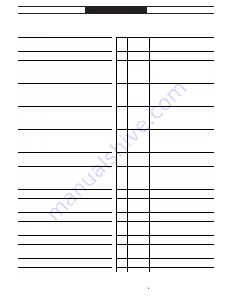
Motor & Handwheel Parts List (Cont.)

REF PART #

DESCRIPTION

REF

PART #

DESCRIPTION

52

PSB1119052 EXT TOOTH WASHER 25MM

111

PSB1119111

CAP SCREW M10-1.5 X 40

53

PSB1119053 BEARING RETAINING NUT M25-1.5

112

PSB1119112

ROLL PIN 4 X 20

54

PSB1119054 TAP SCREW M3 X 6

113

PSB1119113

COMPRESSION SPRING 1 X 12 X 38

55

PSB1119055 DUST COVER

114

PSB1119114

FIXED HANDLE 25 X 90

56

PSB1119056 SENSOR BOX

115

PSB1119115

LOCK NUT M20-1.5

57

PSB1119057

MAGNETIC HEAD

116

PSB1119116

FLAT WASHER 20MM

58

PSB1119058 TAP SCREW M2 X 6

117

PSB1119117

MOTOR BRACKET

60

PSB1119060 GROMMET 12.3 X 18 X 10.4MM

118

PSB1119118

MOTOR BRACKET PIVOT SHAFT

62

PSB1119062 DRAWBAR 5/8-11 X 10-5/16

119

PSB1119119

HOSE CLAMP 3"

68

PSB1119068 HEX NUT M20-1.5

120

PSB1119120

DUST CHUTE 3" X 11-3/4"

69

PSB1119069 STANDOFF-HEX MF M20-1.5 X 44, M12-1.75

121

PSB1119121

TENSION PIVOT SHAFT

70

PSB1119070

FLAT WASHER 12MM

122

PSB1119122

POLY V-BELT 10V X 25L RIBBED

71

PSB1119071

LOCK WASHER 12MM

123

PSB1119123

MOTOR 3HP 230V 3-PH (SB1119)

72

PSB1119072

CAP SCREW M12-1.75 X 80

123-1

PSB1119123-1

MOTOR JUNCTION BOX (SB1119)

73

PSB1119073

BUSHING

123-2 PSB1119123-2 MOTOR FAN COVER (SB1119)

74

PSB1119074

GAS STRUT BRACKET

123-3 PSB1119123-3 MOTOR FAN (SB1119)

75

PSB1119075

ELEVATION HOUSING

123-4 PSB1119123-4 BALL BEARING 6206-2NSE (FRONT) (SB1119)

76

PSB1119076 SET SCREW M5-.8 X 5

123-5 PSB1119123-5 BALL BEARING 6204-2NSE (REAR) (SB1119)

77

PSB1119077

BEVEL GEAR

123

PSB1120123

MOTOR 5HP 230V 3-PH (SB1120)

78

PSB1119078

FLAT WASHER 19.1 X 25.4 X 1.6MM

123-1

PSB1120123-1 MOTOR JUNCTION BOX (SB1120)

79

PSB1119079

KEY 5 X 5 X 12 RE

123-2 PSB1120123-2 MOTOR FAN COVER (SB1120)

80

PSB1119080 WOODRUFF KEY 5 X 20

123-3 PSB1120123-3 MOTOR FAN (SB1120)

81

PSB1119081

HANDWHEEL SHAFT

123-4 PSB1120123-4 BALL BEARING 6206-2NSE (FRONT) (SB1120)

82

PSB1119082 SET SCREW 5/16-18 X 5/16

123-5 PSB1120123-5 BALL BEARING 6204-2NSE (REAR) (SB1120)

83

PSB1119083 COLLAR

124

PSB1119124

FENDER WASHER 10MM

84

PSB1119084 FLAT HD CAP SCR M6-1 X 12

125

PSB1119125

HEX BOLT M10-1.5 X 25

85

PSB1119085 HANDWHEEL TYPE-24 200D X 20B-N X M10-1.5

126

PSB1119126

HEX BOLT M10-1.5 X 55

86 PSB1119086 FOLDING HANDLE 30 X 90, M6-1 X 12

127

PSB1119127

HEX NUT M10-1.5

87

PSB1119087 KNOB BOLT M10-1.5 X 25, 8-LOBE, D60

128

PSB1119128

FIXED HANDLE 38 X 110, M10-1.5 X 15

88

PSB1119088 ELEVATION HOUSING PLATE

129

PSB1119129

TENSION BLOCK

89

PSB1119089 SENSOR MOUNTING BRACKET

130

PSB1119130

HEX BOLT M8-1.25 X 45

90

PSB1119090 CAP

131

PSB1119131

TENSION BRACKET

91

PSB1119091

SET SCREW M8-1.25 X 35

132

PSB1119132

LOCK NUT M8-1.25

92

PSB1119092 HEX NUT M8-1.25

133

PSB1119133

TENSION ASSEMBLY MOUNTING BRACKET

93

PSB1119093 CAP SCREW M10-1.5 X 20

134

PSB1119134

BUTTON HD CAP SCR M8-1.25 X 20

94

PSB1119094 LOCK NUT M10-1.25

173

PSB1119173

KEY 5 X 5 X 25 RE

95

PSB1119095 FENDER WASHER 10MM

174

PSB1119174

MOTOR PULLEY

96

PSB1119096 HEIGHT SENSOR PLATE

175

PSB1119175

FENDER WASHER 8MM

97

PSB1119097

SPACER 10.8 X 20 X 50

176

PSB1119176

CAP SCREW M8-1.25 X 20

98

PSB1119098 BEVEL GEAR

177

PSB1119177

WIRE NUT 10-22 AWG

99

PSB1119099 THRUST BEARING 51202

178

PSB1119178

STRAIN RELIEF TYPE-3 M25-1.5

100 PSB1119100

GASKET

179

PSB1119179

MOTOR CORD 14G 4W 35"

101

PSB1119101

BUSHING

180

PSB1119180

PHLP HD SCR M6-1 X 12

102 PSB1119102

ELEVATION LEADSCREW

181

PSB1119181

SET SCREW M6-1 X 8

103 PSB1119103

ELEVATION GIB

182

PSB1119182

FLAT WASHER 6MM

104 PSB1119104

GAS STRUT

183

PSB1119183

CAP SCREW M6-1 X 12

105 PSB1119105

DUST TRAY

184

PSB1119184

EXT RETAINING RING 20MM

106 PSB1119106

SPINDLE HOUSING

185

PSB1119185

BUTTON HD CAP SCR M5-.8 X 10

107 PSB1119107

LOCK WASHER 10MM

186

PSB1119186

CAP SCREW M8-1.25 X 30

108 PSB1119108

CAP SCREW M10-1.5 X 55

187

PSB1119187

LOCK WASHER 8MM

109 PSB1119109

SPINDLE LOCK SHAFT SEAT

188

PSB1119188

CAP SCREW M8-1.25 X 30

110

PSB1119110

SPINDLE LOCK SHAFT

Summary of Contents for SB1119

Page 1: ...A Tradition of Excellence South Bend Tools May 2021 by South Bend Tools For Machines Mfd Since 3 21 MODEL SB1119 SB1120 3 HP 5 HP SPINDLE SHAPER OWNER S MANUAL...

Page 2: ...on is a process that happens through training and experience If you are not an experienced operator of this type of machinery read through this entire manual then learn more from an experienced operat...

Page 3: ...TY 73 INTRODUCTION 2 Identification 2 Description of Controls Components 3 SB1119 Product Specifications 6 SB1120 Product Specifications 8 SAFETY 10 Understanding Risks of Machinery 10 Basic Machine S...

Page 4: ...Do not use awkward hand positions e Keep fingers away from revolving cutter use fixtures when necessary f Use overhead guard when adjustable fence is not in place Spindle Spindle Control Control Pane...

Page 5: ...wer until instructed to do so later in this manual Untrained users have an increased risk of seriously injuring themselves with this machine Do not operate this machine until you have understood this...

Page 6: ...rack and pinion One turn is approximately 15 8 of movement T Guard Fence Base Lock Knobs Loosen to allow for guard fence base adjustment and tighten to secure U Guard Fence Base Adjusts forward and ba...

Page 7: ...and tighten to secure X Featherboard Guides and supports workpiece as it moves past cutterhead V V X X W W Figure Figure 7 Featherboard controls and components Featherboard controls and components V V...

Page 8: ...x 39 x 58 in Electrical Power Requirement 230V Single Phase 60 Hz Full Load Current Rating 20A Minimum Circuit Size 20A Connection Type Cord Plug Power Cord Included Yes Power Cord Length 120 in Power...

Page 9: ...Depth 3 16 in Table Size Length 39 1 4 in Table Size Width 31 1 2 in Table Size Thickness 3 1 4 in Floor to Table Height 36 1 4 in Table Fence Length 44 1 2 in Table Fence Width 1 1 4 in Table Fence H...

Page 10: ...rical Power Requirement 230V 3 Phase 60 Hz Full Load Current Rating 16 5A Minimum Circuit Size 20A Connection Type Cord Plug Power Cord Included Yes Power Cord Length 120 in Power Cord Gauge 12 AWG Pl...

Page 11: ...Depth 3 16 in Table Size Length 39 1 4 in Table Size Width 31 1 2 in Table Size Thickness 3 1 4 in Floor to Table Height 36 1 4 in Table Fence Length 44 1 2 in Table Fence Width 1 1 4 in Table Fence H...

Page 12: ...are as follows Death or catastrophic harm WILL occur Moderate injury or fire MAY occur Death or catastrophic harm COULD occur Machine or property damage may occur Basic Machine Safety Owner s Manual...

Page 13: ...zard by verifying that all fastening devices are properly secured and items attached to spindles have enough clearance to safely rotate Chuck Keys or Adjusting Tools Tools used to adjust spindles chuc...

Page 14: ...ng Cutter Contact Keep unused portion of cutter below table Use smallest table insert possible Adjust fences and guards as close as practical to cutter or use zero clearance fence or box guard Always...

Page 15: ...process is as follows 1 Unpack the machine and inventory the contents of the box crate 2 Clean the machine and its components 3 Identify an acceptable location for the machine and move it to that loca...

Page 16: ...119 20 Amps Grounding Requirements This machine must be grounded In the event of certain types of malfunctions or breakdowns grounding provides a path of least resistance for electric current in order...

Page 17: ...e Extension Cords Minimum Gauge Size 10 AWG Maximum Length Shorter is Better 50 ft We do not recommend using an extension cord with this machine If you must use one only use it if absolutely necessary...

Page 18: ...agent Inventory NOTICE If you cannot find an item on this list carefully check around inside the machine and packaging materials Often these items get lost in packaging materials while unpacking or t...

Page 19: ...1 Put on safety glasses and disposable gloves 2 Coat all surfaces that have rust preventative with a liberal amount of your cleaner or degreaser and let them soak for a few minutes 3 Wipe off the surf...

Page 20: ...quired by the maintenance and service described in this manual Physical Environment The physical environment where your machine is operated is important for safe operation and longevity of parts For b...

Page 21: ...e power equipment Assembly The machine must be fully assembled before it can be operated Before beginning the assembly process refer to Required for Setup on Page 13 and gather all listed items To ens...

Page 22: ...e 17 Straightedge Table Insert Table Surface Flat Head Screws 1 of 3 Figure Figure 17 Straightedge and surface pattern Straightedge and surface pattern 3 Adjust flat head screws so ends of straightedg...

Page 23: ...iratory illness Reduce your risk by wearing a respirator and capturing the dust with a dust collection system Recommended CFM 400 CFM at Each Port Do not confuse this CFM recommendation with the ratin...

Page 24: ...nexpected results that can lead to serious injury death or machine property damage The test run consists of verifying the following Motor powers up and runs correctly Spindle rotates in correct direct...

Page 25: ...tion If machine does not start safety feature of STOP button is working correctly Congratulations Test run is complete If machine does start immediately turn it OFF and disconnect power Safety feature...

Page 26: ...2 Turns machine OFF To reduce the risk of serious injury when using this machine read and understand this entire manual before beginning any operations The purpose of this overview is to provide the n...

Page 27: ...d yields poor results Excessive Warping Workpieces with excessive cupping bowing or twisting are dangerous to cut because they are unstable and often unpredictable when being cut DO NOT use workpieces...

Page 28: ...most cases the shaper should run in the FOR direction FOR REV Switch FOR REV Switch Figure Figure 32 Location of FOR REV switch Location of FOR REV switch Incorrectly feeding stock feeding WITH rotati...

Page 29: ...and feed rate so the resulting cut is smooth and requires very little sanding to finish Reduce cutter speed or feed rate if your workpiece becomes glazed or burned Increase cutter speed or feed rate i...

Page 30: ...k of injury read and follow entire Owner s Manual carefully and do research on shop made guards and safety jigs Note To make your own box guard see Making Box Guards on Page 43 to find instructions an...

Page 31: ...workpieces start by feeding with your hands then use push sticks to finish the operation so your hands are not on the end of the workpiece as it passes through the cutter Figure Figure 38 Side view of...

Page 32: ...with the table Figure Figure 40 Table inserts front of cutter guard removed Table inserts front of cutter guard removed for clarity for clarity Table Inserts Table Inserts Adjusting Spindle Height The...

Page 33: ...44 Individual fence controls Individual fence controls Fence Fence Lock Handle Lock Handle Fence Fence Lock Knob Lock Knob Operating Spindle Height Digital Readout The Model SB1119 SB1120 is equipped...

Page 34: ...provide support for the workpiece as it passes over the cutter when removing material from the whole face of your workpiece or it can be set up for partial face removal Attempting to operate shaper w...

Page 35: ...8 until workpiece contacts cutter in desired location when pressed against infeed fence Figure Figure 48 Guard fence base adjustment components Guard fence base adjustment components Guard Fence Guard...

Page 36: ...Lock Knob 1 of 2 1 of 2 3 Tighten lock knobs when fence faces will best support workpiece 4 Adjust outfeed fence face to same plane as infeed face 5 Turn shaper ON 6 Run a test piece through shaper se...

Page 37: ...re 54 Cutting with rub collar between cutters Cutting with rub collar between cutters Using Rub Collars Rub collars are used when shaping curved or irregular workpieces such as arched doors or round t...

Page 38: ...shaping Using starting pin for irregular shaping Next swing the work into the cutter while holding the workpiece firmly against the starting pin After the cut has been started the workpiece should be...

Page 39: ...ake a sample cut on a piece of scrap wood 9 If everything is correct feed workpiece along cutter using firm pressure to keep work against rub collar Only feed against cutter rotation Sometimes the sta...

Page 40: ...st decide which rub collars are best suited for your application Always perform test cuts on scrap stock to ensure the pattern works as required Rub Collar Workpiece Template Figure Figure 59 Position...

Page 41: ...install on shaper 3 Position safety guard as low as possible while still clearing cutter or create custom box guard see Making Box Guards on Page 43 4 Adjust infeed and outfeed table featherboards to...

Page 42: ...e best way to reduce the risk associated with shaping inherently dangerous small stock 3 Remove 2 cap screws shown in Figure 61 from each fence mounting bracket Figure Figure 61 Fence mounting bracket...

Page 43: ...ds do not need to get near the cutter to maintain feeding pressure If a kickback does occur featherboards will also slow down or stop the workpiece Figure 63 shows the dimensions of a basic featherboa...

Page 44: ...stick can be used to keep the workpiece firmly against the fence while cutting When using this method only apply pressure before the cutter otherwise pushing the workpiece against or behind the cutter...

Page 45: ...making a custom box guard The thickness of your workpiece will determine the height of the box guard Therefore you will need to build a separate box guard for each workpiece of a different thickness A...

Page 46: ...er This all purpose power feeder boasts a 1 2 HP motor that provides high torque from a single phase power supply It has 7 72 FPM variable speed control and automatically compensates for variations in...

Page 47: ...of these heavy duty roller tables Figure 73 Model T28369 Heavy Duty Roller Table Model T28369 Heavy Duty Roller Table T28923 Bear Crawl Papa Bear Mobile Base We took years of input and months of testi...

Page 48: ...t C2042 Drawer Joint 3 4 Bore 25 8 Diameter 3 4 Cutter Height C2083 Vertical Panel Raising 3 4 Bore 25 8 Diameter 11 2 Cutter Height C2085 Female Sash 3 4 Bore 25 8 Diameter 5 8 Cutter Height C2097Z O...

Page 49: ...maintenance or serious personal injury may result Cleaning Protecting Cleaning the Model SB1119 SB1120 is relatively easy Vacuum excess wood chips and sawdust and wipe off the remaining dust with a dr...

Page 50: ...while machine is not in use 4 Completely cover machine with tarp or plastic sheet that will keep out dust and resist liquid or moisture If machine will be stored in near direct sunlight use cover tha...

Page 51: ...d saw dust Apply a thin coat of lubricant to the racks using a wire brush before replacing the guard fence assembly Adjust the assembly forward and back to distribute the grease Figure Figure 77 Locat...

Page 52: ...e to tension belt 5 Check V belt tension by pressing center of belt with your thumb see Figure 80 If belt is not worn or cracked belt does not need to be replaced Proceed to Step 5 If belt is worn or...

Page 53: ...pplied in the next step 5 Remove spindle and replace bearings inside bearing housing If you need pointers regarding bearing replacement call Technical Support 6 Slide spindle into spindle housing and...

Page 54: ...sting table inserts Calibrating Fence Scales The Model SB1119 SB1120 features forward and reverse spindle rotation either fence face can function as the infeed or outfeed fence However the scales indi...

Page 55: ...Step 3 Figure Figure 88 Location of gib adjustment hardware Location of gib adjustment hardware 4 Loosen gib jam nut shown in Figure 88 Aligning Fence Faces For safe and accurate shaping the fence fac...

Page 56: ...ration A damaged or worn fence should be replaced If choosing to replace or use wooden boards as fence faces follow the instructions below to ensure each is properly flattened and aligned correctly To...

Page 57: ...t contact cutter Aligning Pulleys Pulley alignment is important to the performance of your shaper If the pulleys are just slightly out of alignment the shaper may suffer from power loss and decreased...

Page 58: ...4 Adjusting Spindle Gib The gib controls the smoothness of the slide movement as well as the run out or end play of the spindle Tightening the gib too much will make it hard to adjust the height of t...

Page 59: ...iple readings and make multiple adjustments to the adjusting hex bolt at each corner of the spindle housing Figure Figure 98 Illustration of using machinist s square to Illustration of using machinist...

Page 60: ...of 4 1 of 4 9 When spindle is squared to table re tighten jam nuts without turning hex stand offs 10 Repeat Step 5 to confirm squareness If necessary repeat Steps 7 9 11 Install motor access panel and...

Page 61: ...eed rate cutting speed too fast 2 Decrease feed rate cutting speed Page 27 3 Workpiece crooked fence loose or misadjusted 3 Straighten or replace workpiece adjust fence Page 31 4 Machine undersized fo...

Page 62: ...e boards with straightedge verify parallelism Page 53 Workpiece kicks back toward operator 1 Taking too deep of cut 1 Make several passes of light cuts Always reduce cutting depth when working with ha...

Page 63: ...ctable results including serious injury or fire Motor Wiring The motor wiring shown in these diagrams is current at the time of printing but it may not match your machine Always use the wiring diagram...

Page 64: ...ircuit Board 00273838 Circuit Board 00273838 1 3 2 PE PE X2 X1 4 3 4 14 13 C Motor 230V R L1 S L2 U T1 V T2 W T3 10V ACM AVI AFM MO1 MCM PE MI1 MI2 MI3 MI4 MI5 24 24 DCM DCM RA RB RC RA RC NC21 NC22 L...

Page 65: ...I5 24 24 DCM DCM RA RB RC RA RC NC21 NC22 L1 1 L2 3 L3 5 NO13 T1 2 T2 4 T3 6 NO14 53 61 54 62 SDE MA 18 SDE AP2 11 W6 A B ACM AVI 10V ME300 VFD T1 T3 MI1 54 54 MI2 MI3 13 L3 L3 PE 14 13 T3 T2 T1 PE 53...

Page 66: ...B1120 E L E C T R I C A L Electrical Component Photos Figure Figure 103 Control panel wiring Control panel wiring Figure Figure 104 Spindle RPM and height sensors Spindle RPM and height sensors Figure...

Page 67: ...Photos Cont Figure Figure 106 SB1119 electrical box wiring SB1119 electrical box wiring Figure Figure 107 Motor junction box wiring Motor junction box wiring Figure Figure 108 SB1120 electrical box wi...

Page 68: ...9 16 7 12 11 4 5 10 9 8 7 6 5 4 13 9 16 7 12 17 27 26 14 15 18 9 19 1 20 21 22 23 24 25 2 25 3 25 4 25 5 25 1 29 28 30 31 32 15 9 19 27 26 23 33 18 24 22 21 34 14 1 25 6 148 149 157 158 159 67 65 64...

Page 69: ...FENCE BASE 59 8 PSB1119059 8 E STOP BUTTON RENY 250V 22MM 18 PSB1119018 FENCE SCALE 59 9 PSB1119059 9 POTENTIOMETER W CORD 10K OHM 24G 3W 45 19 PSB1119019 FLAT WASHER 6MM 59 10 PSB1119059 10 GROUND LA...

Page 70: ...19167 AUX CONTACTOR SDE AP2 11 137 PSB1119137 CABLE CHAIN 168 PSB1119168 JUMPER M919 138 PSB1119138 PHLP HD SCR M5 8 X 10 169 PSB1119169 PHLP HD SCR M4 7 X 10 139 PSB1119139 PHLP HD SCR M4 7 X 8 170 P...

Page 71: ...4 86 87 88 58 57 56 89 42 54 174 175 176 122 123 173 C C 40 41 42 43 44 45 46 47 180 182 116 186 187 188 123 1 123 5 123 4 123 3 123 2 177 179 178 184 180 181 182 REF PART DESCRIPTION REF PART DESCRIP...

Page 72: ...E FRONT SB1120 82 PSB1119082 SET SCREW 5 16 18 X 5 16 123 5 PSB1120123 5 BALL BEARING 6204 2NSE REAR SB1120 83 PSB1119083 COLLAR 124 PSB1119124 FENDER WASHER 10MM 84 PSB1119084 FLAT HD CAP SCR M6 1 X...

Page 73: ...63 6 PSB1119063 6 SPACER 1 1 4 ID X 2 OD X 1 2 L 150 PSB1119150 SPINDLE WRENCH 50MM 63 7 PSB1119063 7 SPINDLE 1 1 4 151 PSB1119151 COMBO SCREWDRIVER 1 X 1 4 63 8 PSB1119063 8 HEX NUT M42 2 M40 2 5 152...

Page 74: ...ake the operator aware of the machine hazards and ways to prevent injury The owner of this machine MUST maintain the original location and readability of these safety labels If any label is removed or...

Page 75: ...standard of any domestic or foreign government industry or authority In no event shall South Bend s liability under this warranty exceed the original purchase price paid for this machine Any legal act...

Page 76: ...southbendtools com Printed In Taiwan CS21788...

Reviews: