background image

Vi5000/7000 User Manual

14.4.1 SNAPSHOT SCOPE

®

14.4.1: SNAPSHOT SCOPE

RECALL FILTERING > SNAPSHOT SCOPE

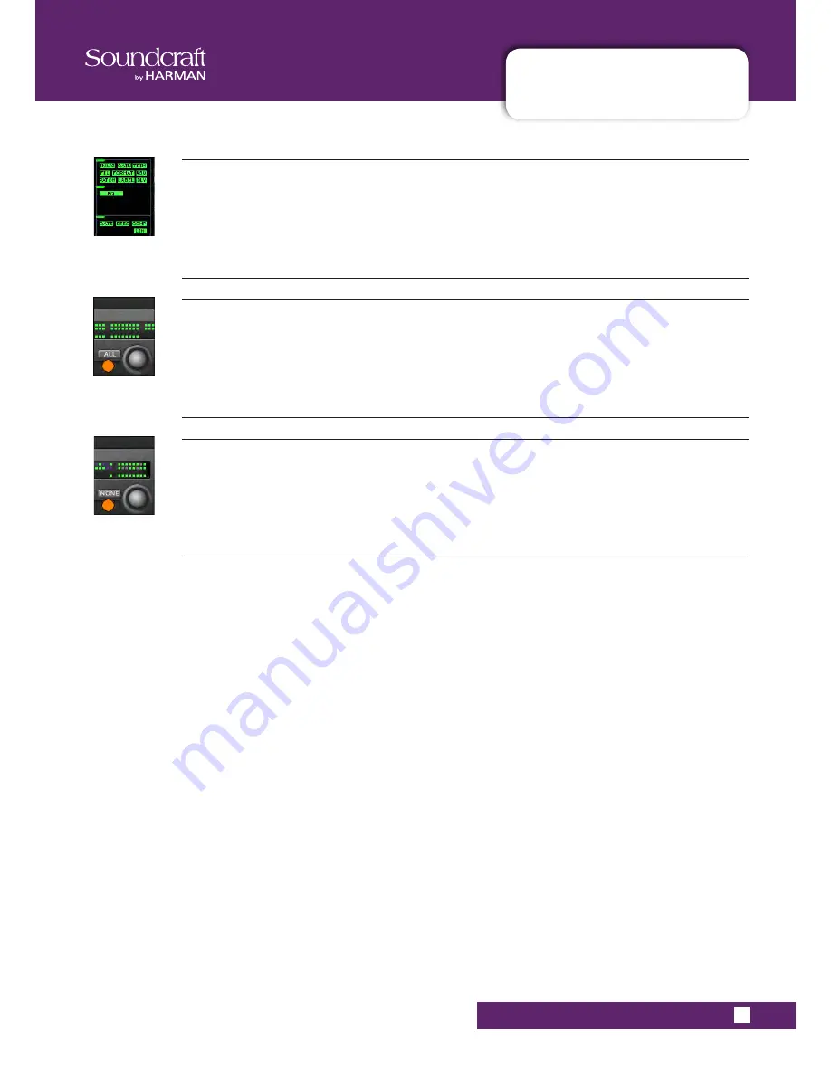
Block Select

Select or deselect individual process blocks from the scope of this cue.

Channel Scope - Select All

Select all busses and VCA masters to be within the scope of this cue.

Channel Scope - Select None

Deselect all channels/busses/VCA masters from the scope of this cue.

Summary of Contents for Vi5000

Page 1: ...User Guide v1 6...

Page 2: ...t occur in a particular installation If this equipment does cause harmful interference to radio or television reception which can be determined by turning the equipment off and on the user is encourag...

Page 3: ...11 2 Input Priority Mode 11 3 Autocancel Behaviour 11 4 Follow Output Solo Mode 12 0 METERING 12 1 Inputs 12 2 Busses 13 0 EDIT SYSTEM COPY PASTE AND LIBRARY 13 1 Copy Paste Undo 13 2 Library Basics...

Page 4: ...layers At a single glance illuminated faders in colours that match those on the Vistonics display show immediately what function a fader is controlling When controlling inputs no illumination is appl...

Page 5: ...een and Yellow must be connected to the terminal in the plug which is marked with the letter E or by the earth symbol The wire which is coloured Blue must be connected to the terminal in the plug whic...

Page 6: ...lified service personnel Servicing is required when the apparatus has been damaged in any way such as power supply cord or plug is damaged liquid has been spilled or objects have fallen into the appar...

Page 7: ...er whilst in transit both to and from the Dealer or Soundcraft and postage must be prepaid 4 This warranty shall only be available if a The Equipment has been properly installed in accordance with ins...

Page 8: ...put Levels Mic Inputs 28dBu max Line Inputs 22dBu max Line Outputs 22dBu max Nominal Operating Level 4dBu 18dBFS Input Output Impedances Mic Inputs 10k All other analogue Inputs 10k Line Outputs 75 AE...

Page 9: ...d to remain local to the control surface and connects via the supplied Console To Local Rack cable The Stagebox connects to the Local rack via MADI and is designed to provide physical inputs and outpu...

Page 10: ...Vi5000 7000 User Manual 4 0 HARDWARE OVERVIEW 4 0 HARDWARE OVERVIEW HARDWARE OVERVIEW...

Page 11: ...RFACE CONNECTIONS HARDWARE CONTROL SURFACE CONNECTIONS The rear of the control surface has essential audio connections data connection to the Local Rack MIDI USB and HiQnet Ethernet connections as wel...

Page 12: ...USB memory devices and or USB keyboard USB memory sticks can be used to save and load console Snapshot show and library data See sections 13 and 14 for more detail A USB keyboard can also be connecte...

Page 13: ...and also the connections to the remote Stage Box The audio processing inside the SCore is independent of the control surface This means that the audio will continue to pass even if the control surface...

Page 14: ...where acoustic noise is an issue Please note that reducing the speed from the factory set value is ONLY allowable when the console is operated in an air conditioned environment where the ambient temp...

Page 15: ...has occurred An illuminated green LED indicates the presence of a card an illuminated red LED warns of a card error Note that there is a RECONFIG button behind a small hole at the bottom right of the...

Page 16: ...e are shown in section 4 2 4 There are 12 single slots for I O cards identified with letters A L the HD cards are not included in these 12 slots Double slot cards such as MADI and Dante take the lette...

Page 17: ...l data and status information about the cards loaded into the frame Each pair of links can handle up to 192 channels in both directions giving a total I O capacity for the rack of 384 channels The HD...

Page 18: ...e Primary Bridge Card output the MIC Card D Sub connector and the BLU Link Card input and output to the corresponding connections on the rear of the Active Breakout Unit BLU Link in out Blu Link out i...

Page 19: ...Vi5000 7000 User Manual 4 2 4 LOCAL RACK CONNECTIONS 4 2 4 SCore CONNECTIONS HARDWARE LOCAL RACK CONNECTIONS...

Page 20: ...ear panel Primary power supply The primary power supply connects directly to the IEC inlet and provides a full range AC inlet converting 100V to 240V ac to 24V DC The Stage box is fitted with two powe...

Page 21: ...er Manual 4 5 DIMENSIONS DRAWINGS 4 5 DIMENSION DRAWINGS HARDWARE DIMENSIONS DRAWINGS 326 4mm 1436 9mm 326 4mm 333 4mm 725 1mm 97 1mm 229 3mm 1731 9mm 326 4mm 333 4mm 326 4mm 725 1mm 108 5mm 97 1mm 22...

Page 22: ......

Page 23: ...ERATIONS OVERVIEW OPERATIONS OVERVIEW The illustrations in this manual show the Vi5000 console The Vi7000 has an extra eight wide Inputs Bay Where relevant the text illustrations will note operational...

Page 24: ...trol being referred to is used to indicate a panel mounted key or encoder is used to indicate a Vistonics VST key or encoder is used to indicate a button on a touch screen COLOURS The following table...

Page 25: ...e default input channel mode the input touch screens show the Input EQ Dynamics assigned internal insert FX Bus outputs and panning sections of the input channel strip Touching one of these opens that...

Page 26: ...e button can open a configuration page in the Touch area it shows a sign on the button If the configuration page is already open the button will be labelled with a sign Pressing the button in that sta...

Page 27: ...ontributions and more to the input faders The input bay vistonics touch screen areas normally show eight channel strip processing blocks for the eight corresponding faders The input bay VST areas norm...

Page 28: ...NPUT BAY 3 4 NAVIGATION The Master Bay touch screen meters can be used as a navigation device simply touch a block of eight meters and those channels both inputs and outputs are mapped to the right ha...

Page 29: ...refore be easy to forget which function is currently being controlled especially when grabbing a fader in a hurry The main principle of FaderGlow is therefore to indicate the actual function type that...

Page 30: ...be latching stay on or Momentary on when pressed off when you let go If you hold a button down it will have a momentary action If you press a button and let go within half a second it will latch Syst...

Page 31: ...information see the Inputs reference chapter 6 Output Vistonics Group These buttons provide control over the VST section functionality of the Master Bay vistonics screens For example the PAGE A and P...

Page 32: ...ay channel strips For More information see the Output Channels reference chapter 7 Next Last NEXT and LAST buttons for moving through the loaded Cuelist These buttons have to be enabled in the Setting...

Page 33: ...unction is to enable the SOLO path from its channel or bus to the monitoring system However if a touch area page is open pressing a SOLO SEL from another channel within its own bay of eight channels m...

Page 34: ...igned to the contribution levels from the Outputs to the Soloed Matrix Output Note the lower FLW key has an additional function in allowing VCAs to control the Aux sends of input channels See the Mute...

Page 35: ...HRS PAN and USER 1 2 keys on the Encoder Mode panel See the Inputs reference chapter 5 for more information The VST Input Bay encoders default to Aux 1 and 2 though can be assigned a variety of functi...

Page 36: ...nnels to or from the gang with the channel SOLO SEL buttons Entering Gang Mode does not cancel any solos of any type that are active at the time The Solo system continues to work as it was when Gang M...

Page 37: ...ng the channel s input area on the touch screen then pressing the CH LABEL button in the VST area Labelling can be done with the displayed on screen keyboard or an external USB keyboard The on screen...

Page 38: ...t channel control areas on the console The main channel strips including the Vistonics screen sections are for control of input channel parameters routing and patching The INPUT FADER PAGES buttons ar...

Page 39: ...ur main layers of input channel strips and a further five user definable layers available The ALL BUSSES button maps the output busses to the input channel strips as described further in the Outputs r...

Page 40: ...pages layers Select one of these buttons to map that user defined fader layer to the console The User layers are defined by pressing the FADER PAGES SETUP button All Busses Mode Map the output busses...

Page 41: ...efined by the input ENCODER MODE buttons The Default function is control over the channel s analogue input gain For more information see the Inputs Encoder Mode reference section 6 3 Input Channel Str...

Page 42: ...more information Pre Indicator Bus send routing indicator When Bus sends are assigned to channel faders using FLW mode the PRE indicator lights to indicate when the send is set to a Pre fader source C...

Page 43: ...utions to that bus FaderGlow The channel fader is colour coded depending on its function Input channel levels are not colour coded The other FaderGlow colours are Aux Sends ORANGE Groups GREEN Matrix...

Page 44: ...active the channel encoders are disabled and have no function the previous function is remem bered however You can assign a range of input channel parameters to the User 1 and User 2 assignments by en...

Page 45: ...annel parameters including EQ and dynamics controls Press the VST Encoder SET button to confirm the selection and press SETUP again to exit Setup Mode Mode User 1 Switch the input Encoders to control...

Page 46: ...o Aux is assigned to a VST encoder row and if the PAN key is active the encoder will control the Aux Pan rather than the contribution level If both Auxes assigned to Row 1 2 are Stereo Auxes both Rows...

Page 47: ...ault or the USER layer Note that only one FLW can be active at a time VST Mode USER Assign the two VST Encoder rows as user definable output controls The default assignments are Aux 3 and Aux 4 Use th...

Page 48: ...nput section touch screen area is at the top of the Vistonics input channel strip area colour coded blue The input section consists of that channel s input source selection pre amp and gain stages con...

Page 49: ...ed and the corresponding input touch field is highlight ed in orange Input Gain Adjust the analogue input gain This is an analogue gain stage before analogue to digital conversion Input Pad Reduce the...

Page 50: ...The affected frequency range is shown graphically in the EQ section of the touch screen HI CUT IN OUT Switch the digital HI CUT filter in and out When the digital HI CUT filter is switched in the HI...

Page 51: ...effects If an input channel is paired you will also have to option to select L or R assignment from the same screen The IN 1 and IN 2 field text areas will show the selected source Channel Label Activ...

Page 52: ...r coded red The EQ section consists of four full range parametric bands with shelving response available to the LF and HF bands Frequency Control Adjust the centre frequency band pass or cut off frequ...

Page 53: ...l Adjust the gain applied to the defined filter band EQ Band In Switch the selected EQ band into the Equaliser signal path Please note there is also an EQUALISER IN button to switch the equaliser sect...

Page 54: ...er be a GATE or DeEsser section the other two are a COMPRESSOR and a LIMITER All three sections can be turned on or off independently The dynamics section of the Vistonics touch screen shows gain redu...

Page 55: ...t either the GATE or DeEsser function for the first dynamics process The top line of dynamics controls adapt to this selection Gate Threshold Set Adjust the gate threshold level Gate In Include the Ga...

Page 56: ...normal signal level and the gated signal level Gate Side Chain Solo Switches the Gate Side Chain signal to the Solo buss For monitoring the signal being used as the gate key The signal used for testin...

Page 57: ...with the gate lo cut filter this creates a band pass filter for side chain control of the gate De Esser Sensitivity Adjust the sensitivity of the De esser process The de esser can be used instead of...

Page 58: ...Ess Band Solo Solo the De esser dynamic filter Helps pinpoint the Ess band most suited to the current signal De Ess Filter Frequency Adjust the centre frequency of the De ess dynamic filter De Ess Fil...

Page 59: ...er full attenuation has been reached Compression Ratio Adjust the compression ratio The ratio between the normal signal level and the attenuated compressed signal level The higher the ratio the more c...

Page 60: ...In Activate Limiter Include the Limiter in the dynamics section Limiter Attack Time Adjust the Limiter attack time The time taken for the limiter to reach full attenuation Limiter Release Time Adjust...

Page 61: ...utings in Green The controls vary depending on whether you are working on Auxiliaries or groups Auxiliary Send Level Adjust the send level from the input channel to the numbered Aux Buss The Orange ba...

Page 62: ...be no balance control visible when PAN mode is activated Group Buss Routing Route the input channel signal to the numbered group buss The corresponding group assign bar in the buss touch screen area i...

Page 63: ...ing Adjusts panning to the Master L R and C busses depending on pan mode chosen If the channel is paired the balance can be adjusted If the Pan MODE is set to LCR an additional WIDTH field becomes ava...

Page 64: ...at interrupts the channel signal flow In any Insert Select page all available insert points can be patched to physical I O by touching the on screen SETUP button You can return to insert assignment by...

Page 65: ...ut for this input channel Direct Output Gain Adjust the gain of the channel s Direct Output Direct Output Point Select the point in the input channel s signal path for the Direct Output tap Options ar...

Page 66: ...put buss the processing block will appear next to the Dynamics block in the touch screen The BSS 901 is a four band parametric Dynamic Equaliser which allows frequency selective compression and expan...

Page 67: ...ession or expansion will reduce over the Release time period back to zero compression or expansion A fast Release means that the signal will return to normal faster DEQ Above Below Threshold Choose th...

Page 68: ...Vi5000 7000 User Manual 7 0 OUTPUTS OUTPUTS 7 0 OUTPUTS Auxiliaries Groups and LCR Mix busses...

Page 69: ...to 16 busses can be configured as mono or stereo Matrix MTX outputs with full processing each with up to 24 or 32 Vi 5000 Vi7000 respectively configurable sources including busses effectively creating...

Page 70: ...Master Bay These are dedicated faders and controls and are never used for anything else To access the LRC Bus mastering page simply press the MASTERS SEL button The processing page will appear on the...

Page 71: ...rs The output levels of the LRC Master outputs are always controlled by their dedicated faders Those faders are never used for anything else L C R Link setup Set up LRC Master bus EQ and GEQ linking L...

Page 72: ...e for Master LRC busses L C R BSS DEQ Access the BSS DPR901ii Dynamic EQ if assigned The EQ controls will appear in the VST section of the Master Bay touch screen You can assign any of the available B...

Page 73: ...bus masters to input bay 3 right hand bay by touching the relevant metering group in the Master Bay touch screen You then patch physical outputs and name the busses by touching the Panning Insert pro...

Page 74: ...If Aux is selected and if the format field is set to stereo then the CHPAN field is enabled Pan Follows Channel Set Pan follows channel for a stereo bus Set this so the panning into a stereo auxiliary...

Page 75: ...us masters and two ways of accessing the output bus processing and parameters Master Bay VST Encoders Bus master levels are available on the VST Encoders in the Master Bay with groups of bus masters s...

Page 76: ...g any of the channel metering areas in the Master Bay touch screen area you assign that bank of eight to the right hand input bay Three banks of eight outputs are located on the top row on the Master...

Page 77: ...up to control which functions and which masters are available Talkback Assign Mode Assign the TB ASSN function to the bus masters VST buttons See the Talkback and Oscillator chapter for more informati...

Page 78: ...utput May duplicate a fader controlled bus master if the ALL BUSSES fader page is active on the input bays or one of the output fader pages A D is active on the master bay Bus Solo Solo this bus outpu...

Page 79: ...ectors The VCA button maps VCA masters 1 8 to the Master bay faders Buttons A through D map busses 1 32 to the Master Bay channel strips in groups of eight Buttons E maps VCA masters 9 16 to the eight...

Page 80: ...put level FaderGlow The Bus Master fader is colour coded depending on its function The Bus Master FaderGlow colours are Aux Sends ORANGE Groups GREEN Matrix Contribution CYAN VCA Master 1 8 BLUE VCA M...

Page 81: ...PROCESSING OUTPUTS MASTERS PROCESS The bus output processing chain has a parametric EQ block a BSS Graphic Equaliser block GEQ a dynamics block and a Pan Insert block You can also label the bus assig...

Page 82: ...nnel Strip Dynamics The controls are identical to those of the input channels except there are no De Esser modes available for output busses and no Gate or DeEsser modes available if the console is ru...

Page 83: ...h the ALLBUSS button and selecting the GEQ block from the corresponding channel s touch screen area or by selecting a bus SOLO SEL button while the Master Bay Vistonics button assign is set to Solo Se...

Page 84: ...of the currently active GEQ to 0dB Press and hold for 2 secs to activate GEQ In Activate or deactivate the currently selected GEQ GEQ Fader On Button Indicates which GEQ bands are non zero and flatte...

Page 85: ...s section or by touching the relevant meter group in the Master Bay touch screen In this case the buss masters and assignments will be mapped to the right hand input bay Matrix Control To map matrix c...

Page 86: ...atrix Pan Encoder Pan control for stereo Matrix sources If the Matrix bus is stereo the Pan control will appear above each Matrix Source fader allowing the selected source to be positioned within the...

Page 87: ...s are controlled for the channel faders This means there are 33 possible sets of 16 VCA groups A more detailed reference for this functionality is included later in the this chap ter section 9 3 Each...

Page 88: ...below Mute Groups Operation Mute Setup Press the MUTE VCA GROUPS SETUP button then chose a Mute Group button to configure that group The SETUP button will glow blue when pressed The chosen mute group...

Page 89: ...rom A to E along with Bus Output faders using the User Defined fader page setup The VCA page cannot be remapped and always contains VCA 1 8 VCA Masters ON Buttons Master On Off button for all of the V...

Page 90: ...els as members of the VCA Group Select the VCA Group you require by pressing its SOLO Sel button first Aux VCA Mode Bulk On Off Switch all VCA Masters in the Master bay between Aux VCA Mode and Normal...

Page 91: ...roups has been extended to control of groups of Aux sends as well as channel faders Because there can be up to 32 Auxiliary sends configured on the console this means that there are up to 32 sets of V...

Page 92: ...to the Aux feeds from those channels assigned to the VCAs At this point the VCA Master SOLO SEL keys have no function The VCA ON switch controls the Aux send On Off on the member channels 6 To select...

Page 93: ...G OVERVIEW The monitoring system has three main sources Monitor A Monitor B and Headphones These are fed by a choice of sub sources including Solos LCR Talkback return and two user defined stereo sour...

Page 94: ...Vi5000 7000 User Manual 10 0 MONITORING 10 0 MONITORING MONITORING OVERVIEW...

Page 95: ...itor A is an LCR output Monitor B is an LR out put and the headphones output is LR to the headphone socket on the front of the console You can select a variety of sources for the monitoring outputs in...

Page 96: ...r Control monitoring volume level AFL and PFL indication These two LEDs show if an active solo is a PFL or an AFL Monitoring Setup Display the Monitor Setup Page on the master screen The SETUP key glo...

Page 97: ...adjusted from OFF to 10dB to allow solos to be heard in the context of a mix that has a reduced level Solo Input Priority Activate Input Priority Mode Allows an Output Solo to remain active whilst an...

Page 98: ...the monitoring setup page as well as monitoring delay Monitoring Input Solo Source Choose either input channel PFL AFL or AUTO as the Input Solo source The AUTO option works by automatically selecting...

Page 99: ...nt auto cancelling of Solos depending on Input Priority INPUT PRI Mode With Input Priority OFF input and output solos cancel other active solos of any type With Input Priority ON an input solo will ca...

Page 100: ...turn to the monitor or phones outputs allows a continuous feed of a return TB signal to be heard regardless of solo or other souce activation and therefore can be used as a shout feed without needing...

Page 101: ...llows the headphones and or monitor speakers to be time aligned to the output from the main PA system when working at a distance from the PA speakers The delay applies to all three monitor outputs Mon...

Page 102: ...e User A and User B monitoring sources When selected the source assignment screen is displayed on the touch screen You can assign any available input individually to the left and right User channels i...

Page 103: ...ications where the solos of in ear monitor mixes could be programmed to appear only on Monitor B for example which could have an in ear headphone system connected to it In this example conventional we...

Page 104: ...er Solo generates an AFL or PFL Solo depending on the mode selected in Monitor Setup default is AFL for outputs The post fade Output signal is switched onto the Solo Bus In all cases when SIP Mode is...

Page 105: ...rity of cases in live sound mixing only one channel is soloed at any time so it has become common practice for solos to autocancel so that pressing any solo cancels the previous one and only one solo...

Page 106: ...soles The Faderglow colour will illuminate in this case to indicate the type of bus contributions being assigned to the input faders Orange for Aux sends and Green for Group sends although the faders...

Page 107: ...ons in its DSP which means that the audio signal inside the mixer cannot be overloaded If the signal level is too high at the master output meters it is necessary only to pull down the master fader le...

Page 108: ...in the channel signal flow and the metering peak hold time can be selected in the main set tings screen via the MENU button in the Settings tab 12 1 INPUT METERING Input Level Meter Shows the input l...

Page 109: ...ynamics from Stereo Bus Masters are always linked there fore both GRMs show the same value The overload LED indicates a value that is higher than Full Scale analogue output stage clipping Mix Master M...

Page 110: ...elect any set of parameters in use on the desk and store them in the internal library independent of the Show Files and export to or import from a USB storage device If the console is in either copy o...

Page 111: ...Gain and all associated switches 48V PAD Phase Inv etc Fader and Mute VCA Mute Group Assignment FX settings Parameters not included with a whole bus copy but that CAN be added individually are the ou...

Page 112: ...tly set to the Small Hall FX type then only the Small Hall parameters will be copied Paste Enter paste mode to Paste any channels processing blocks parameters or Lexicon FX settings selected in Copy m...

Page 113: ...ei ther Copy or Paste mode It works in much the same way as the basic copy and paste mode To Paste from the library simply hit the PASTE button select a library item then touch a target on the console...

Page 114: ...ations of channel or bus parameters Currently only a combination of EQ and Dynamics can be stored in the Misc category but this may be extended with a future software update The Library file system it...

Page 115: ...d in the Default Library alongside the read only factory default Entries or one or more new Libraries can be created which will then only contain user stored Entries User Libraries In addition to the...

Page 116: ...sed in Copy or Paste Mode It allows you to navigate the console library and perform import export operations with connect USB storage devices Important In Copy mode you must have your intended source...

Page 117: ...File Delete the currently highlighted Library or Library item You cannot delete a complete Library that is currently loaded Save As Save a copy of the library under a new name New Library Create a ne...

Page 118: ...ith a Library item selected in the internal Library right hand side of the file screen and a USB stor age device selected hitting the Export arrow will copy the selection into currently selected Libra...

Page 119: ...obal filtering which affects all snapshots This uses the ISO buttons on the console The global filtering system can isolate console channels blocks and parameters from either snapshot or show file rec...

Page 120: ...the Master Bay touch screen Data Sockets Accept USB Storage devices for show storage and Media playback There are two more USB sockets on the rear of the console Undo Action Undo the effect of pressin...

Page 121: ...l Isolate protect this channel or selected parameters from the effects of snapshot recall or Show recall The ISO buttons are found on the console channel strips Isolate whole channels by pressing that...

Page 122: ...is also displayed next to the channel meters in the Master Bay touch screen during normal operation Cue Selection Select next and previous snapshots in the cue list Like the UP and DOWN buttons on th...

Page 123: ...y of the entire Cue including the desk snapshot and any MIDI or other events that were part of the original Cue Move Cue Move the selected cue or cues to a new position in the cue list The MOVE button...

Page 124: ...e original cue numbering remain unchanged Scroll The Cue List Scroll through the cue list using the encoder Usually faster than the Up and Down buttons Apply Changes To Scoped Parameters In Selected C...

Page 125: ...Vistonics VST area For example by touching the Cue 2 entry in the cue list in the MIDI column that cue s MIDI functions MIDI based recall and a MIDI message output list will be available in the VST ar...

Page 126: ...plus MIDI timecode recall event set tings and the GO TO CUE local sequencing function Timecode On Off Activate MIDI timecode based recall for this cue Copy Timecode Copy the current incoming MIDI time...

Page 127: ...led Can be very useful for firing a number of events from one cue activation When combined with the Crossfade function it s possible to create pseudo dynamic Cues Go To Cue On Activate the GO TO CUE f...

Page 128: ...s plug in snapshot data to the console via an ethernet link when the console s STORE button is pressed and the data is automati cally stored in the Cue list in a separate UA snapshot Snapshot Recall E...

Page 129: ...riable parameters are included in the crossfade The exceptions are EQ and Hi Lo Cut frequencies and all Lexicon FX parameters The Crossfade time is global for all parameters and all channels and busse...

Page 130: ...Triggering Enable Activate the MIDI input recall trigger for this cue When active this cue will be recalled when the specified MIDI message is received from the specified MIDI device MIDI In Message...

Page 131: ...DI Output Event Number Set the MIDI output event number to be edited There are up to 20 MIDI output events available for each cue The encoder scrolls through the list of events and allows the paramete...

Page 132: ...all 20 events MIDI Event Output Channel or Device ID Select a MIDI device as the MIDI event carrier Depending on the type of MIDI message selected either a MIDI channel Out1 ch1 16 and Out2 ch1 16 or...

Page 133: ...d GPO output sections The inputs section sets an input to be used as a recall trigger for this cue while the output section defines an output to be triggered when the cue is recalled The cue GPIO syst...

Page 134: ...s snapshot The blackout turns off all console lights except for two that will deactivate the blackout When the console is in Blackout state pressing the F6 key in the Master bay will cancel the blacko...

Page 135: ...HiQnet Venue number can be transmitted from a Cue recall and will send a message to all Harman devices in a HiQnet network reuesting them to recall a specific preset The preset will be mapped to the...

Page 136: ...efore there are two different types of snapshot filtering Global Filtering also called Isolation and Snapshot Scope Global Filtering only affects recall and is controlled with the console s ISO button...

Page 137: ...obal Filter or ISO and the Snapshot Scope work together in series so in order for a parameter to be recalled from the Snapshot memory it must have its Scope setting set to ON and must NOT be isolated...

Page 138: ...c of console channels shown in the VST area Both can be used to set a specific scope for the cue Note that Scope is actually a non destructive filter stored with the cue the full snapshot is always st...

Page 139: ...NAPSHOT SCOPE Block Select Select or deselect individual process blocks from the scope of this cue Channel Scope Select All Select all busses and VCA masters to be within the scope of this cue Channel...

Page 140: ...istonics screen changes to purple to indicate the All Isolated state To quickly isolate groups of channels or busses the Gang function can be used To isolate parts of a channel or buss you can use eit...

Page 141: ...ck is a independent signal path normally from a microphone input to group and physical outputs activated with push to talk talkback buttons on the console itself It is most often used to allow the con...

Page 142: ...46 66dB by 3 internal jumpers which are located on the PCB that is located adjacent to the rear panel talkback mic connector This is set by default to a mid range setting If the Oscillator is active...

Page 143: ...al Route the TB signal to any available output in the console s IO system Change the EXT TB assignment via the Talkback Oscillator SETUP screen Talkback Presets 1 3 Press to talk momentary and latchin...

Page 144: ...llator Talkback SETUP button is pressed More detailed setup functions appear in the VST area colour coded orange The oscillator can also be patched to the Input Channels by using the OSC key in the In...

Page 145: ...20kHz Oscillator Bus Assignment Used in conjunction with the Oscillator to Bus touch screen switch Opens an output assignment page where you can select any of the 32 group busses or the Mix L R and C...

Page 146: ...automatically selected The button opens up an assignment selection page in the master touch screen area where you can select any available microphone input Talkback External Output Assign the Talkback...

Page 147: ...o talk directly to the console operator The talkback function must be enabled via the MONITORING setup page by selecting the TB RET touch screen button for Monitor A B or Phones outputs Talkback Retur...

Page 148: ...onality including GPIO and MIDI setup Show loading duplicating and export import Tielines input output patching setup Lexicon FX operation and more Menu Button Access the main menu The main menu will...

Page 149: ...website from time to time are applied to the console The Platform version number denotes the operating system version which is not updatable except by replacing the console s inter nal SSD drive The...

Page 150: ...side of the page Normally the front panel USB Data Sockets will be used USB1 and 2 but it is possible to connect USB data storage devices to the rear panel USB sockets USB3 and USB4 and select the re...

Page 151: ...rent show parameters as a new Show You will be prompted to input a new show name via the on screen keyboard or an external USB keyboard Show Defaults Display the default Shows in the Show file list Th...

Page 152: ...eet application Import Channel Labels Choose to import channel labels with a Show export If a file named Soundcraft Vi Channel labels csv is found in the root of the external storage device and it is...

Page 153: ...before loading a new one The Show Snapshot allows the complete status of the console to be recorded with the Show even if no Snapshots have been saved Settings Recorded Within A Show Snapshot s Show S...

Page 154: ...tput insert All Channel Bus assigns levels Pre Post states and Channel Labels All Channel Patch ordering All I O routing All I O controls Settings Not Recorded PFL SOLO switch status SEL Switch status...

Page 155: ...ack and Vi Stagebox and provides electrically isolated opto coupler inputs with integrated current sink 5 to 24 VDC and electrically isolated outputs using SPST relay contacts 5 VDC and Gnd supply pin...

Page 156: ...n Select Select the function to be assigned to the GPI pin Depending on the function selection the Parameter field may or may not be available For example the Channel Mute CH MUTE function requires a...

Page 157: ...FDR START function requires a channel assignment set this using the Parameter field the Talkback Output TB OUTPUT function does not require any additional parameter Available functions Channel Mute Fa...

Page 158: ...ed edge for this GPO pin Choose either Rising Falling or Both If you choose Both the Polarity field will become available Polarity Select Set the Polarity of the output The encoder changes the polarit...

Page 159: ...n menu Section 16 9 When this is done the available input channel count is reduced by half to 64 External Clock External clock source selected not a control The console switches to External Wordclock...

Page 160: ...nnections from an input connector to a output connector They are a path through the mixer with no processing and no mixing and there they do not use up any DSP channels The console supports up to 128...

Page 161: ...where you can choose any available console input Tieline Output Patch Assign a physical output to this Tie Line The Red OUT buttons open an output assign page in the main touch screen area where you...

Page 162: ...eference for more specific information Lexicon FX Engine n Select a Lexicon FX processor to control Algorithm selection and related parameters are mapped to the VST section of the Master Bay Vistonics...

Page 163: ...dly names for each MIDI channel or Device ID to help with identifying a source or destination device in other MIDI setup screens such as the MIDI Events list in the Cue List List TX Channels Display t...

Page 164: ...ination device in other MIDI setup screens such as the MIDI Events list in the Cue List MIDI Device Name MIDI Device Name display Allows the friendly name to be entered using on screen QWERTY keyboard...

Page 165: ...tgoing timecode events and incoming timecode When enabled the Show name displayed in the Master Bay touch screen is replaced by the timecode display Timecode Display On Off Enable or disable the timec...

Page 166: ...so displayed at the top right of the master section s main screen in the Error Log Dis play Area The message is cleared from the main screen after the Log page has been viewed by the user Note that th...

Page 167: ...Vi5000 7000 User Manual MENU LOG 16 8 LOG MENU 16 8 LOG MENU Automatic Scrolling Cause the most recent message to be displayed as the currently selected one Clear Log Clear the error log list...

Page 168: ...ole including the date and time plus input meter source point and general meter peak hold time delay EQ and graphic EQ Set Date And Time Send date and time settings controls to the VST section of the...

Page 169: ...olled in banks of four or eight bands using the Output Fader page buttons Set Delay Units Change the units used in input output and monitoring delay adjustments You can choose between milliseconds met...

Page 170: ...oloured label The label colour indicates the overall state of the system monitoring page A green label indicates that this device is running correctly whereas a red label indicates an error condition...

Page 171: ...to allow a level of integration between a HiQnet enabled wireless microphone system and a Soundcraft Vi Series console This section is also used to set up a network IP address for use with both ViSi...

Page 172: ...page in the main menu All Parameters from the four Effects Units and for all Effects Type are stored in the desk Snapshots LEXICON Effects Format Depending on the selected effect type the FX processor...

Page 173: ...Vi5000 7000 User Manual 17 0 FX 17 0 FX LEXICON FX...

Page 174: ...t you then need to select an input to patch to the output of that FX unit Each FX processor can be patched in three ways Aux Masters can be patched to the inputs of FX units input channel inputs can b...

Page 175: ...nsert output delay block in the channel strip then use the BUS OUT PATCH or INS PATCH options in the VST section to bring up the relevant patching options onto the touch screen Simply select the Lexic...

Page 176: ...Insert block from the bottom of the touch screen channel strip then use the INSERT patch option to select an FX Unit Touch the FX button on the top left of the touch screen to show the available FX se...

Page 177: ...mation that follows will allow any F key to be mapped to the tap function of any FX unit in the event that a Vi4 or 6 show is being used In order to assign the TAP functions of FX units to the F keys...

Page 178: ...RITHMS For each of the FX processors an individual FX Type can be selected The FX Types are grouped into the following categories Reverb Delay and Miscellaneous You can select algorithms by hitting th...

Page 179: ...like a voice Drum Hall has a higher diffusion setting which is necessary to smooth out faster transient signals found in drums and percussion instruments In addition to general instrumental and vocal...

Page 180: ...tar or percussion Spring Reverb Mono In Stereo Out A Spring reverb is created by a pair of piezoelectric crystals one acting as a speaker and the other acting as a micro phone connected by a simple se...

Page 181: ...dimension of the space Audio is temporarily muted when Size is changed Reverb Time Adjust the amount of time the reverb can be heard Higher settings increase reverberation times which are usually ass...

Page 182: ...s are often rolled off with this parameter resulting in more natural sounding reverberation Setting a low frequency for this parameter can actually shorten the reverb time as it damps the audio as it...

Page 183: ...ust the level of early reflections within the reverb Feedback Delay Change the resonant frequencies of Plate reverb Feedback Level Adjust a Plate reverb s presence and prominence Boing Increase or dec...

Page 184: ...are a calculated percentage of the actual delay time from 1 100 for example if the delay time is 500ms and Tap 1 is set to 50 and Tap 2 is set to 100 Tap 1 time would be 250ms and Tap 2 time would be...

Page 185: ...ulates the old studio trick of flipping a tape over playing it backwards through a tape delay and recording the effect The delays build up from softer to louder creating the sensation that the delays...

Page 186: ...t This creates a series of delay repeats each slightly attenuated until they become inaudible Higher settings create more repeats lower settings reduce the number of repeats When this knob is turned f...

Page 187: ...g the level of delay is kept down but in the pauses the level of the repeats is brought up to provide a smooth tail to the vocal phrases The Ducker Threshold sets the level at which the input signal h...

Page 188: ...einforcements with characteristic swishing tunnelling and fading sounds Phaser Stereo The Phaser automatically moves frequency notches up and down the spectrum of the signal by means of a low fre quen...

Page 189: ...itar and electric piano rhythm parts In fact this program is a great alternative to the Chorus and Tremolo effects for any sound source Pitch Shift Stereo This effect shifts the frequency spectrum of...

Page 190: ...ave triangle wave and random Regeneration Controls the amount of modulated signal being fed back into the input creating feedback Higher amounts add more resonance to the signal Pre Delay Determines t...

Page 191: ...drive Gain Adjust overdrive gain to the preamp section of the rotary speaker effect Horn Min Rotary effect only Minimum speed of the HF rotary horn The speed limits are used when the speed parameter i...

Page 192: ...fect Increases or decreases the Doppler pitch effect The Doppler effect is a rise and fall in pitch experienced by an observer when a sound source is moving towards or away from them due to a compress...

Page 193: ...ding streamlining of the workflow and increase in speed of problem diagnosis Compatible wireless systems can be connected to the console using the HiQnet socket on the back of the control surface via...

Page 194: ...Dante port this connection uses Shure ACN protocol rather than HiQnet Wireless access point or router for connection of ViSiRemote iPad remote control app Soundcraft Realtime Rack for snapshot store r...

Page 195: ...connected to the console without using a switch but in most cases it is better to use one A computer running HiQnet System Architect software may also be connected to the switch and if a wireless rout...

Page 196: ...ction Subnet Mask Entry Set the subnet mask For use with Manual MAN IP Configuration Use the row of VST encoders to dial in the subnet mask HiQnet node address entry console Set the console s HiQnet N...

Page 197: ...et node address of the AKG Hub4000Q to which each microphone is connected For Shure systems the NET column shows the receiver ID number It is possible for multiple Hub4000Qs and multiple Shure systems...

Page 198: ...tivate wireless system detection When on the console will auto detect Shure wireless systems When off detection of receivers is not possible any previously detected units will be disabled and will be...

Page 199: ...DISPLAYS VM STATUS DISPLAYS The console displays VM wireless system status information in two places the main channel strip display in the input channel touch screen area input block and in the VST a...

Page 200: ...cs touch screen area provides instant feedback on the status of VM microphones via icons for each of the monitoring elements Microphone Muted Shows microphone muted state Shows red MUTE icon if the mi...

Page 201: ...n the input block is selected Battery Level Seven segment transmitter battery level indication Red segments 0 1 indicate one hour or less remaining The Amber segment segment 2 indicates 25 percent of...

Page 202: ...f remaining battery life in hours and the internal gain of the microphone Note that for AKG systems this information is display only there is no control possible over the AKG microphones other than wi...

Page 203: ...display of the chosen receiver to flash allowing it to be more easily identi fied among a rack of others RF Strength All Microphone types Radio Frequency signal strength Shows signal level in bargraph...

Page 204: ...standards to ensure all Dante devices are synchronized at all times Dante runs on standard computer networking hardware and does not require dedicated network infrastructure The Audinate Dante Virtua...

Page 205: ...count DIP switch S1 and the factory default setup of 64 in 64 out To create other channel count settings that are not marked on the switch add any two or 3 switch settings together ie to select 48chs...

Page 206: ...ion Diagram Refer to the previous page for information on the function of these switches Note Switches point down to select channel count ignore the ON legend on switch body Diagram shows the default...

Page 207: ...the Dante card this may be via a switch router or direct to either the PRIMARY or SECONDARY ports The LINK indicator on the card will begin to flash indicating an active connection NOTE A crossover ca...

Page 208: ...be set as preferred master Slave to External Word Clock When checked the Dante card will clock from the console internal word clock if not checked the console must be clocked to the Dante card or syst...

Page 209: ...s On the right pane of the window lists the Tx channels from other devices that are available for subscription by the current device You may drag and drop Available Channels to Receive Channels Transm...

Page 210: ...ection of an appropriate latency NOTE The 0 15 msec setting is unavailable on Vi Dante cards as these include an internal switch Factory Reset Allows remote reboot of the Dante interface and to reappl...

Page 211: ...s case care must be taken to avoid accidently making any connection between the two parallel networks Note All devices on a Dante network MUST be set to the same Mode Switched or Redundant otherwise t...

Page 212: ...patched to receive audio from the Dante option card The FOH console mix is returned to two spare channels of the monitor console and the direct outputs of those inputs are in turn patched to the syste...

Page 213: ...ossibilities become near endless in this alternative system All system outputs leave via a Dante enabled processor such as the BSS BLU 806 An additional console does a live stereo mix down for web str...

Page 214: ...Flexibility and Expansion Option Cards I O Solutions and Accessories for Soundcraft Vi Series consoles...

Page 215: ...ooked up and shares the same redundant MADI cable capability For Vi1 a compatible card for the console is required to be purchased separately The unit comes complete with twin redundant power supplies...

Page 216: ...ression Si Compact Si Performer Si Series and Vi Series consoles via a MADI HD card fitted to the option card slot The mic preamps used in the Mini Stagebox are identical to those in the Compact Stage...

Page 217: ...type connector female MIC IN CARD Four analogue microphone line inputs electronically balanced with 24 bit 48 kHz delta sigma A D converters mic line sensitivity gainsetting in 1 dB steps low cut fil...

Page 218: ...NUMBER 3G SDI CARD The 3G SDI card can de embed up to 16 audio channels from an SDI Serial Digital Interface stream and re embed them Embedder DeEmbedder card only back on to the stream for onward tr...

Page 219: ...ls to be sent to received from a Dante network As well as providing audio exchange with other Dante enabled equipment the card also allows 64 channels of audio to be connected directly to a PC or Mac...

Page 220: ...the Cat 5 version but on industry standard SC fibre connectors Two duplex SC connectors allow dual redundant cabling with automatic switchover Connection distances of up to 1500m are possible using t...

Page 221: ...S IN CARD The AES In card provides 8 channels of AES EBU inputs via 4 balanced XLRs Sync LEDs indicate a valid input lock Each input pair incorporates sample rate converters which can be bypassed usin...

Page 222: ...range so Si and Vi consoles may be mixed on a network 4 The ViSi app may be used as an offline familiarisation tool Simply connect a Wireless Router to the HiQnet port on the console and mix remotely...

Page 223: ......

Page 224: ......

Page 225: ...Road Potters Bar Hertfordshire EN6 3JN UK T 44 0 1707 665000 F 44 0 1707 660742 E soundcraft marketing harman com Soundcraft USA 8500 Balboa Boulevard Northridge CA 91329 USA T 1 818 920 3212 F 1 818...

Reviews: