1-16
DV
/D
8 D
ubb
in
g (DV/
D
8
t
DV
D)
69
US
Dubbing From a DV/D8
Format Tape to a DVD
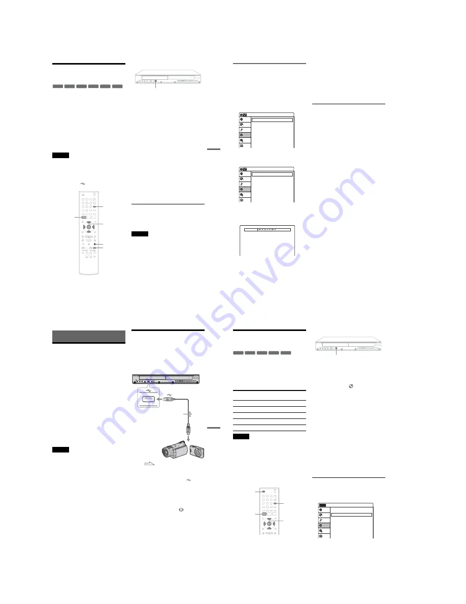
You can simply record the entire contents of a DV/
D8 format tape onto a disc. The recorder controls
the DV camcorder for the whole process. You can
also select the scenes on the tape using the on-
screen display. See “Dubbing selected scenes” on
page 70.
◆
How titles and chapters are created
The dubbed contents on the disc become one title,
and the title is then divided into chapters at either
5 or 15-minute intervals, according to the “DVD
Auto Chapter” setting of “Features” in the “Setup”
display.
Notes
• To play the dubbed disc on other DVD equipment,
finalize the disc (page 66). If you set “Auto Finalize” to
“On” in the “Features” setup (page 85), the Auto
Finalize function works for DVD-RWs (Video mode),
DVD-Rs (Video mode) and DVD+Rs after dubbing.
For details, see page 67.
• Do not connect the
(USB) jack at the same time.
1
Place a recordable disc on the disc tray.
About inserting discs, see page 49 for details.
2
Insert the source DV/D8 format tape into
your DV camcorder, and set the camcorder
to video playback mode.
3
Press INPUT repeatedly to select “DV.”
4
Press REC MODE repeatedly to select the
recording mode.
5
Set the “DV/D8 Audio Input” setting in the
“Audio” setup (page 84).
Select the desired audio if multiple audio
channels are recorded on the tape.
6
Press ONE-TOUCH DUBBING on the
recorder.
The recorder rewinds the tape in the DV
camcorder and then starts recording the tape
contents from the beginning.
When playback of the tape stops, One Touch
Dubbing ends automatically.
To stop recording
Press
x
STOP.
Note that it may take a few seconds for the
recorder to stop recording.
Notes
• During dubbing, timer recordings are unavailable.
• You cannot record the date, time, or contents of a DV/
D8 format tape onto the disc.
• If you record from a DV/D8 format tape with a
soundtrack that is recorded in multiple sampling
frequencies (48 kHz, 44.1 kHz, or 32 kHz), no sound,
or an unnatural sound may be output when passing the
sampling frequency switch point on the disc.
• The recorded picture may be momentarily affected if
the picture size of the source image changes, or if there
is nothing recorded on the tape.
• Noise may occur if you switch the audio sampling
mode (48 kHz/16 bits
t
32 kHz/12 bits).
-RW
VR
-RW
Video
+
RW
+
R
-R
VR
-R
Video
1
1
2
2
3
3
4
4
5
5
6
6
7
7
8
8
0
0
9
9
REC MODE
INPUT
SYSTEM
MENU
M
/
m
/
<
/
,
,
ENTER
x
STOP
REC
ONE-TOUCH DUBBING
,
continued
70
US
Dubbing selected scenes
You can fast forward, rewind, play in slow motion,
and stop the tape to select scenes using the on-
screen display.
1
Follow steps 1 to 5 of “Dubbing From a DV/
D8 Format Tape to a DVD” (page 69).
2
Select “Dubbing” on the System Menu,
and press ENTER.
3
Select “DV/D8 Dubbing,” and press
ENTER.
4
Select “DV/D8 Simple Dubbing,” and
press ENTER.
The “DV Tape Mode” display appears.
If “DV” or “DV Camera Mode” is displayed,
check that the DV camcorder is correctly
connected, turned on, and set to the video
playback mode.
5
Find the dubbing start point on the tape,
and stop or pause playback.
Press
<
/
,
to select
m
,
x
,
X
,
y
,
H
, or
M
on the TV screen and press ENTER to
find the point, and stop or pause with
x
or
X
.
6
Press
,
to select
z
on the TV screen, and
press ENTER.
Dubbing starts.
To stop recording
Select
x
on the TV screen, and press ENTER.
Note that it may take a few seconds for the
recorder to stop recording.
To turn off the display for DV/D8 dubbing
Press INPUT.
z
Hint
If “DV Camera Mode” appears on the screen, you can use
z
on the TV screen to record the camera image directly
on the recorder.
Dubbing
10:10 AM
DV/D8 Dubbing
USB Dubbing
Setup
Disc Setting
Edit
Title List
Timer
Dubbing
DV/D8 Dubbing
10:10 AM
DV/D8 Simple Dubbing
DV/D8 One Touch Dubbing
Setup
Disc Setting
Edit
Title List
Timer
Dubbing
DV Tape Mode
U
SB D
ubbi
ng
(U
SB
t
DV
D
)
71
US
USB Dubbing (USB
t
DVD)
Before USB Dubbing
This section explains the following dubbing
methods via the USB jack:
• Dubbing all the video contents of the connected
DVD camcorder to make a backup DVD
(page 72).
• Dubbing the selected video contents of the
connected HDD camcorder to a DVD (page 73).
• Copying JPEG image files to a DVD (page 75).
◆
Connectable USB devices (as of January 2008)
The following Sony devices can be connected to
this recorder:
DVD camcorder: DCR-DVD108
HDD camcorder: DCR-SR42
Digital still camera: DSC-W200/T100/T20/W80/
W90/H7/H9/G1
z
Hint
If your HDD camcorder has no USB jack, use the
Handycam Station supplied with the camcorder.
Notes
• During dubbing, do not disconnect the USB device.
• USB cables exclusive for supplying power cannot be
used.
• Connect the camcorder or digital still camera directly to
the recorder, not via a USB hub or other USB device.
• Do not connect the DV IN jack at the same time.
Connecting to the USB jack
You can connect a USB device (DVD camcorder,
HDD camcorder, digital still camera, etc.) to the
USB jack on the recorder.
Also refer to the instruction manual supplied with
the connected USB device before connecting.
1
Turn on the recorder and the USB device.
2
Connect the USB device to the
(USB)
jack on the recorder.
3
Set your USB device to the USB connecting
mode, if necessary.
As an example for the HDD camcorder:
When “USB SELECT” appears on the
camcorder’s screen, select “
COMPUTER.”
For details, refer to the operating instructions
supplied with the connected USB device.
LINE 2 IN
DV IN
ONE-TOUCH
DUBBING
REC
VIDEO
L(MONO) AUDIO R
DVD recorder
to
(USB)
: Signal flow
USB cable
(not supplied)
to USB output
DVD camcorder, HDD
camcorder, digital still
camera, etc.
72
US
Dubbing From a DVD
Camcorder (DVD Backup)
You can dub all the contents of a DVD in the DVD
camcorder to another DVD as a backup copy. Be
sure to finalize a source DVD before dubbing.
◆
Usable discs for backup DVDs
Use a new or blank DVD of the same type as the
source DVD.
Notes
• When using a DVD+R/DVD-R, make sure that the disc
is new, unformatted, and has not been loaded into the
recorder. Since blank discs are automatically formatted
once loaded, you can use them for other purposes, such
as timer recording.
• When using a DVD+RW/DVD-RW, use unused or
blank discs only, as the operation erases any pre-
recorded data.
• Insert the disc only after step 4 when the disc tray has
opened. Otherwise the recorder may automatically
format the disc, making it unusable for DVD Backup.
1
Press INPUT repeatedly to select “USB.”
2
Connect your DVD camcorder and set it to
USB connecting mode.
For example, select “
COMPUTER” when
“USB SELECT” appears on the camcorder’s
screen.
Check the USB indicator lights up in the front
panel display.
3
Press ONE-TOUCH DUBBING on the
recorder.
The display asks for confirmation. Note that
you cannot stop dubbing halfway.
4
Select “Start” and press ENTER.
The disc tray opens.
5
Place a recordable disc, and press
Z
OPEN/CLOSE to close the disc tray.
The progress bar display appears, and the
recorder starts dubbing the entire contents of
the source DVD.
Do not disconnect the USB cable while
dubbing is in progress. When dubbing is
complete, the progress bar disappears.
To dub using the on-screen menu
1
After step 2 above, press SYSTEM MENU.
2
Select “Dubbing,” and press ENTER.
Source DVD
(8 cm)
Recordable DVD
(12 cm)
DVD+RW
DVD+RW
DVD-RW (Video mode) DVD-RW
DVD-RW (VR mode)
DVD-RW
DVD-R (Video mode)
new DVD-R
DVD+R DL
new DVD+R
-RW
VR
-RW
Video
+
RW
-R
Video
+
R
,
1
1
2
2
3
3
4
4
5
5
6
6
7
7
8
8
0
0
9
9
SYSTEM
MENU
M
/
m
/
<
/
,
,
ENTER
INPUT
Z
OPEN/
CLOSE
REC
ONE-TOUCH DUBBING
Dubbing
10:10 AM
DV/D8 Dubbing
USB Dubbing
Setup
Disc Setting
Edit
Title List
Timer
Dubbing
No Disc
Summary of Contents for RDR-GX360
Page 39: ...4 1 DVD Main PCB 4 4 4 3 COMPONENT SIDE ...
Page 40: ...4 6 4 5 CONDUCTOR SIDE ...
Page 41: ...4 8 4 7 4 2 Jack PCB COMPONENT SIDE ...
Page 42: ...4 10 4 9 CONDUCTOR SIDE ...
Page 43: ...4 12 4 11 4 3 Function PCB COMPONENT SIDE CONDUCTOR SIDE ...
Page 44: ...4 14E 4 13 4 4 Front PCB COMPONENT SIDE CONDUCTOR SIDE ...
Page 46: ...5 4 5 3 5 1 S M P S Jack PCB ...
Page 47: ...5 6 5 5 5 2 Power Jack PCB ...
Page 48: ...5 8 5 7 5 3 AV Decoder DVD Main PCB ...
Page 49: ...5 10 5 9 5 4 AV Link TS in_Out DVD Main PCB ...
Page 50: ...5 12 5 11 5 5 Connector DVD Main PCB ...
Page 51: ...5 14 5 13 5 6 DDR DVD Main PCB ...
Page 52: ...5 16 5 15 5 7 HDMI CEC DVD Main PCB ...
Page 53: ...5 18 5 17 5 8 HDMI TDA9984 DVD Main PCB ...
Page 54: ...5 20 5 19 5 9 Host1 Flash Remulator I F DVD Main PCB ...
Page 55: ...5 22 5 21 5 10 IEEE1394_DV DVD Main PCB ...
Page 56: ...5 24 5 23 5 11 PCMIO VIO VDAC DVD Main PCB ...
Page 57: ...5 26 5 25 5 12 USB DVD Main PCB ...
Page 58: ...5 28 5 27 5 13 User Interface DVD Main PCB ...
Page 59: ...5 30 5 29 5 14 Input_Output Jack PCB ...
Page 60: ...5 32 5 31 5 15 Connector Jack PCB ...
Page 61: ...5 34 5 33 5 16 Front Micom Jack PCB ...
Page 62: ...5 36 5 35 5 17 Function Timer Function PCB ...
Page 63: ...5 38E 5 37 5 18 Front AV Front PCB ...
Page 79: ...7 1 RDR GX360 7 REPAIR PARTS LIST 7 1 Exploded Views 7 2 7 2 Electrical Parts List 7 3 ...
Page 85: ...REVISION HISTORY Ver Date Description of Revision 1 0 2008 03 New RDR GX360 ...


