

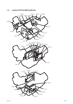


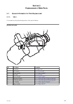


1-3-8.
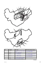
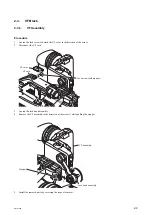
VF Block
VF block consists of the following four boards.
• IF-1242 board
• IF-1209 board
• VR-351 board
• SW-1603 board
IF-1242 Board
The video signal for the viewfinder is sent from the DCP-64 board (IC2303) through the CN-3634 board to the IF-1242
board in the viewfinder block. The serial video signal is converted to a parallel signal in IC102 on the IF-1242 board,
and the parallel signal is returned to a 10-bit video signal and a synchronization signal, and then these signals are sent
to the IF-1209 board.
Furthermore, the IF-1242 board acquires the PEAKING, BRIGHT, and CONTRAST setting data for LCD images from
the VR-351 board through IC301. IC301 also acquires switch information on menu display, ZEBRA display, and image
inversion from the SW-1603 board
IF-1209 Board
Video signals from the IF-1242 board are converted (Y/C to RGB) and adjusted in the picture quality for the LCD panel
on the IF-1209 board, and are then sent to the LCD panel.
Adjustment values are stored in IC100. This board also controls the LCD backlight by IC302.
VR-351 Board
VR-351 board has knobs for setting PEAKING, BRIGHT, and CONTRAST.
SW-1603 Board
SW-1603 board has switches for displaying menu and ZEBRA and inverting images.
PMW-300
1-12


