background image

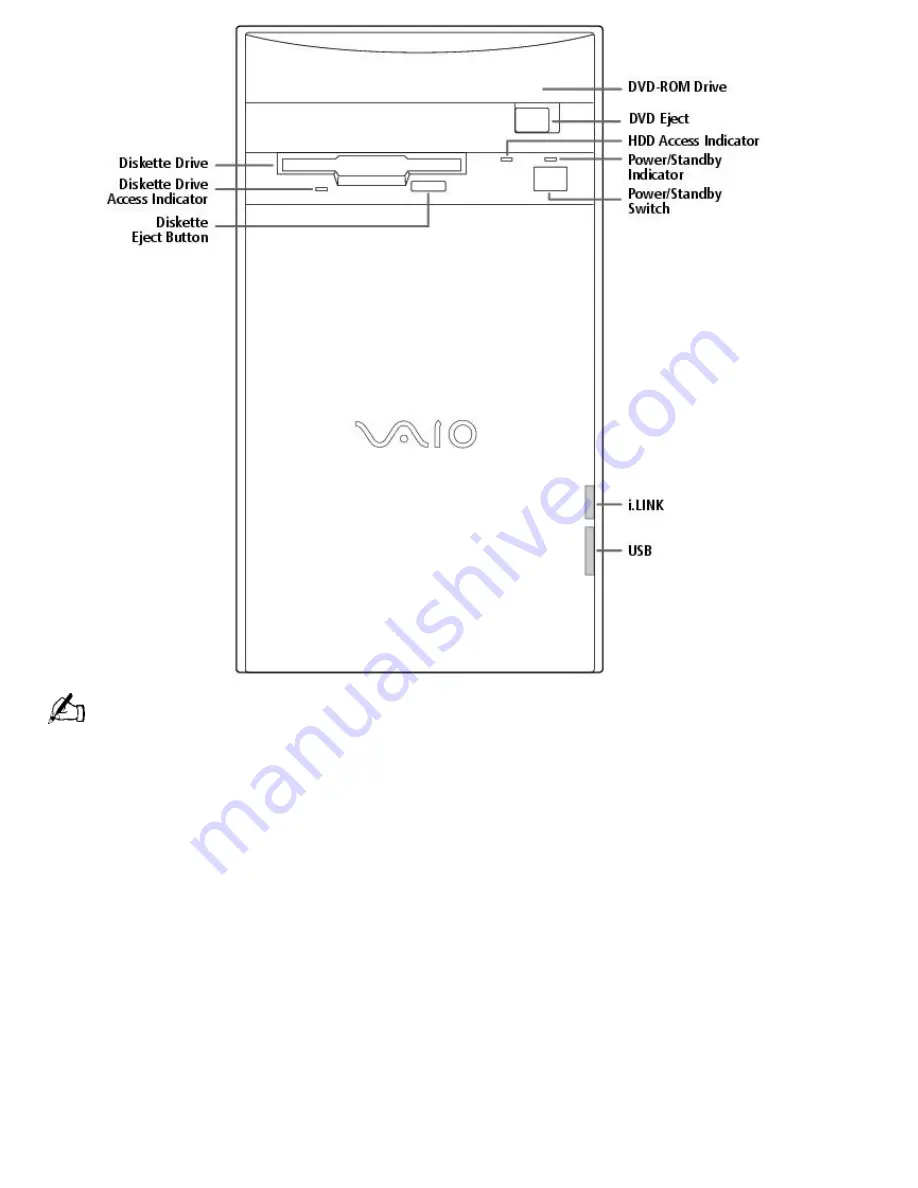
For your convenience, your computer includes USB and i.LINK connectors on both the front and back panels,

allowing you to connect to either set of connectors. The i.LINK connector on the front of your system is a 4-pin
connector. 

Supplementary Information 

You can access the online version of 

Read Me First

 from the Help Center in VAIO Space. 

Optimal DVD Performance 

Due to nonstandard implementation of Microsoft Active Movie components in some DVD game
titles, some DVD game titles may not play correctly. DVD standards are still evolving. Some DVD
titles may require software or hardware components that were not available when your VAIO
MicroTower was designed and manufactured. 

The DVD Control Panel can be accessed by right-clicking anywhere in the DVD video window and
selecting Panel. 

If you select the standby mode for your monitor and allow the system to turn off the monitor, it is
recommended that you restart your computer before playing DVD titles. 

VAIO Smart   Keyboard Default Settings 

The VAIO Smart Keyboard programmable buttons come with the following applications as their
default settings: 

Page 161

Summary of Contents for PCV-E302DS VAIO

Page 1: ...s a trademark of Lucent Technologies Inc and Rockwell International All other trademarks are trademarks of their respective owners Safety Information Owner s Record The model number and serial number are located on the back of your Sony computer Record the model and serial numbers in the space provided here Refer to the model and serial number when you call your Sony Service Center Model Number __...

Page 2: ...xcessive REN s on the telephone line may result in the devices not ringing in response to an incoming call In most but not all areas the sum of the REN s should not exceed five 5 0 To be certain of the number of devices that may be connected to the line as determined by the total REN s contact the telephone company to determine the maximum REN for the calling area This modem uses the USOC RJ 11 te...

Page 3: ...business other entity or individual sending the message and the telephone number of the sending machine or such business other entity or individual In order to program this information into your facsimile see your fax software documentation You are cautioned that any changes or modifications not expressly approved in this manual could void your authority to operate this equipment Page 3 ...

Page 4: ...a digital video camera such as the Sony Digital Handycam or other digital imaging devices to an i LINK connector on either the front or back of your system This state of the art technology allows audio video devices to function as true multimedia peripherals creating a new interface technology between your computer and A V products S PDIF Optical Digital Audio Output connector Transfer digital aud...

Page 5: ...ows 98 Getting Started manual explains how to use the basic features of the Windows operating system Recovery CDs System Recovery CD s Application Recovery CD s Other Setting up your VAIO MicroTower poster Packet containing special product offers Software Library The Software Library contains the Microsoft software license agreement Sony end user license agreement and the following CDs Adobe Photo...

Page 6: ...uter For your convenience your computer includes USB and i LINK connectors on both the front and back panels allowing you to connect to either set of connectors i LINK connectors on the back of your system are 6 pin connectors Front Panel Overview The front panel of your MicroTower allows for access to the diskette and DVD ROM drives It also includes USB and i LINK ports that allow you to connect ...

Page 7: ...titles some DVD game titles may not play correctly DVD standards are still evolving Some DVD titles may require software or hardware components that were not available when your VAIO MicroTower was designed and manufactured The DVD Control Panel can be accessed by right clicking anywhere in the DVD video window and selecting Panel If you select the standby mode for your monitor and allow the syste...

Page 8: ... Resume from Standby Mode There are two ways to resume system functionality when your computer is in standby mode You can use any one of the following methods Press any key such as the Enter key Tap the power switch on the front panel It may take up to 30 seconds for your system to recover stored information and resume functionality The screen remains blank while the system is resuming functionali...

Page 9: ...nel select the checkbox for Automatic receive fax To select the modem that ships with your VAIO computer select Sony Internal Modem on the Modem panel Click the Properties button to confirm the correct modem properties When this is complete click the OK button When you complete the Modem Configuration Wizard panel a successful configuration message displays The Registration Wizard screen appears o...

Page 10: ...fault setup and want to reinitialize the parameters follow these steps 1 In the Adobe Premiere LE application select Compression from the Make menu The Compression Settings dialog box appears 2 In the Method list box select Sony DV software CODEC 3 Click OK to close the screen 4 From the Create menu select Preset The Preset dialog box appears 5 Select the parameters for Time Base Compress Output a...

Page 11: ...es that you can record is approximately 9 minutes 30 seconds You can record stereo audio stereo 1 while capturing video You cannot add audio on the stereo 2 track after capturing the video data You cannot use different audio modes on the same tape You should perform a separate capture for each audio mode you wish to use DVgate Motion does not support hard disk compression You should not use disk c...

Page 12: ...In the Add New Hardware wizard that appears when you restart click the Next button until you are prompted for the location of the drivers The audio drivers are located on the Application Recovery CD in G drivers audio AL98091701 English Using AC 3 to S PDIF Output Minidisc player recorders DAT player recorders and older digital receivers do not support Dolby Digital AC 3 You should not use the AC ...

Page 13: ...ate of purchase Quicken Basic Intuit Inc Web site http www intuit com support phone 900 555 4688 hours 7 days a week 24 hours a day SHORT cinema journal 2014 Corporation Web site http www dvdmags com phone 310 821 9843 fax 310 821 7846 e mail my2cents dvdmags com hours M F 9 AM 5 PM PT Specifications Model PCV E302DS PCV E308DS Processor 350 MHz Pentium II 450 MHz Pentium II Hard Disk Drive 10 2 G...

Page 14: ...ansfer standard 1X rate is 150 kbytes s The average data transfer rate is 17X 2550 kbytes s 2 Maximum speed for faxing is 14 4 kbps Your modem is capable of downloading at 56 kpbs using K56flex Technology or V 90 Your phone service online service or Internet Service Provider however may not support this technology or operate at this speed 3 Six pin i LINK connectors on the rear of the system each ...

Page 15: ...a digital video camera such as the Sony Digital Handycam or other digital imaging devices to an i LINK connector on either the front or back of your system This state of the art technology allows audio video devices to function as true multimedia peripherals creating a new interface technology between your computer and A V products S PDIF Optical Digital Audio Output connector Transfer digital aud...

Page 16: ...ows 98 Getting Started manual explains how to use the basic features of the Windows operating system Recovery CDs System Recovery CD s Application Recovery CD s Other Setting up your VAIO MicroTower poster Packet containing special product offers Software Library The Software Library contains the Microsoft software license agreement Sony end user license agreement and the following CDs Adobe Photo...

Page 17: ...ter For your convenience your computer includes USB and i LINK connectors on both the front and back panels allowing you to connect to either set of connectors i LINK connectors on the back of your system are 6 pin connectors Front Panel Overview The front panel of your MicroTower allows for access to the diskette and DVD ROM drives It also includes USB and i LINK ports that allow you to connect U...

Page 18: ...itles some DVD game titles may not play correctly DVD standards are still evolving Some DVD titles may require software or hardware components that were not available when your VAIO MicroTower was designed and manufactured The DVD Control Panel can be accessed by right clicking anywhere in the DVD video window and selecting Panel If you select the standby mode for your monitor and allow the system...

Page 19: ... Resume from Standby Mode There are two ways to resume system functionality when your computer is in standby mode You can use any one of the following methods Press any key such as the Enter key Tap the power switch on the front panel It may take up to 30 seconds for your system to recover stored information and resume functionality The screen remains blank while the system is resuming functionali...

Page 20: ...nel select the checkbox for Automatic receive fax To select the modem that ships with your VAIO computer select Sony Internal Modem on the Modem panel Click the Properties button to confirm the correct modem properties When this is complete click the OK button When you complete the Modem Configuration Wizard panel a successful configuration message displays The Registration Wizard screen appears o...

Page 21: ...fault setup and want to reinitialize the parameters follow these steps 1 In the Adobe Premiere LE application select Compression from the Make menu The Compression Settings dialog box appears 2 In the Method list box select Sony DV software CODEC 3 Click OK to close the screen 4 From the Create menu select Preset The Preset dialog box appears 5 Select the parameters for Time Base Compress Output a...

Page 22: ...es that you can record is approximately 9 minutes 30 seconds You can record stereo audio stereo 1 while capturing video You cannot add audio on the stereo 2 track after capturing the video data You cannot use different audio modes on the same tape You should perform a separate capture for each audio mode you wish to use DVgate Motion does not support hard disk compression You should not use disk c...

Page 23: ...In the Add New Hardware wizard that appears when you restart click the Next button until you are prompted for the location of the drivers The audio drivers are located on the Application Recovery CD in G drivers audio AL98091701 English Using AC 3 to S PDIF Output Minidisc player recorders DAT player recorders and older digital receivers do not support Dolby Digital AC 3 You should not use the AC ...

Page 24: ...ate of purchase Quicken Basic Intuit Inc Web site http www intuit com support phone 900 555 4688 hours 7 days a week 24 hours a day SHORT cinema journal 2014 Corporation Web site http www dvdmags com phone 310 821 9843 fax 310 821 7846 e mail my2cents dvdmags com hours M F 9 AM 5 PM PT Specifications Model PCV E302DS PCV E308DS Processor 350 MHz Pentium II 450 MHz Pentium II Hard Disk Drive 10 2 G...

Page 25: ...ansfer standard 1X rate is 150 kbytes s The average data transfer rate is 17X 2550 kbytes s 2 Maximum speed for faxing is 14 4 kbps Your modem is capable of downloading at 56 kpbs using K56flex Technology or V 90 Your phone service online service or Internet Service Provider however may not support this technology or operate at this speed 3 Six pin i LINK connectors on the rear of the system each ...

Page 26: ...a digital video camera such as the Sony Digital Handycam or other digital imaging devices to an i LINK connector on either the front or back of your system This state of the art technology allows audio video devices to function as true multimedia peripherals creating a new interface technology between your computer and A V products S PDIF Optical Digital Audio Output connector Transfer digital aud...

Page 27: ...ows 98 Getting Started manual explains how to use the basic features of the Windows operating system Recovery CDs System Recovery CD s Application Recovery CD s Other Setting up your VAIO MicroTower poster Packet containing special product offers Software Library The Software Library contains the Microsoft software license agreement Sony end user license agreement and the following CDs Adobe Photo...

Page 28: ...ter For your convenience your computer includes USB and i LINK connectors on both the front and back panels allowing you to connect to either set of connectors i LINK connectors on the back of your system are 6 pin connectors Front Panel Overview The front panel of your MicroTower allows for access to the diskette and DVD ROM drives It also includes USB and i LINK ports that allow you to connect U...

Page 29: ...itles some DVD game titles may not play correctly DVD standards are still evolving Some DVD titles may require software or hardware components that were not available when your VAIO MicroTower was designed and manufactured The DVD Control Panel can be accessed by right clicking anywhere in the DVD video window and selecting Panel If you select the standby mode for your monitor and allow the system...

Page 30: ... Resume from Standby Mode There are two ways to resume system functionality when your computer is in standby mode You can use any one of the following methods Press any key such as the Enter key Tap the power switch on the front panel It may take up to 30 seconds for your system to recover stored information and resume functionality The screen remains blank while the system is resuming functionali...

Page 31: ...nel select the checkbox for Automatic receive fax To select the modem that ships with your VAIO computer select Sony Internal Modem on the Modem panel Click the Properties button to confirm the correct modem properties When this is complete click the OK button When you complete the Modem Configuration Wizard panel a successful configuration message displays The Registration Wizard screen appears o...

Page 32: ...fault setup and want to reinitialize the parameters follow these steps 1 In the Adobe Premiere LE application select Compression from the Make menu The Compression Settings dialog box appears 2 In the Method list box select Sony DV software CODEC 3 Click OK to close the screen 4 From the Create menu select Preset The Preset dialog box appears 5 Select the parameters for Time Base Compress Output a...

Page 33: ...es that you can record is approximately 9 minutes 30 seconds You can record stereo audio stereo 1 while capturing video You cannot add audio on the stereo 2 track after capturing the video data You cannot use different audio modes on the same tape You should perform a separate capture for each audio mode you wish to use DVgate Motion does not support hard disk compression You should not use disk c...

Page 34: ...In the Add New Hardware wizard that appears when you restart click the Next button until you are prompted for the location of the drivers The audio drivers are located on the Application Recovery CD in G drivers audio AL98091701 English Using AC 3 to S PDIF Output Minidisc player recorders DAT player recorders and older digital receivers do not support Dolby Digital AC 3 You should not use the AC ...

Page 35: ...ate of purchase Quicken Basic Intuit Inc Web site http www intuit com support phone 900 555 4688 hours 7 days a week 24 hours a day SHORT cinema journal 2014 Corporation Web site http www dvdmags com phone 310 821 9843 fax 310 821 7846 e mail my2cents dvdmags com hours M F 9 AM 5 PM PT Specifications Model PCV E302DS PCV E308DS Processor 350 MHz Pentium II 450 MHz Pentium II Hard Disk Drive 10 2 G...

Page 36: ...ansfer standard 1X rate is 150 kbytes s The average data transfer rate is 17X 2550 kbytes s 2 Maximum speed for faxing is 14 4 kbps Your modem is capable of downloading at 56 kpbs using K56flex Technology or V 90 Your phone service online service or Internet Service Provider however may not support this technology or operate at this speed 3 Six pin i LINK connectors on the rear of the system each ...

Page 37: ...a digital video camera such as the Sony Digital Handycam or other digital imaging devices to an i LINK connector on either the front or back of your system This state of the art technology allows audio video devices to function as true multimedia peripherals creating a new interface technology between your computer and A V products S PDIF Optical Digital Audio Output connector Transfer digital aud...

Page 38: ...ows 98 Getting Started manual explains how to use the basic features of the Windows operating system Recovery CDs System Recovery CD s Application Recovery CD s Other Setting up your VAIO MicroTower poster Packet containing special product offers Software Library The Software Library contains the Microsoft software license agreement Sony end user license agreement and the following CDs Adobe Photo...

Page 39: ...ter For your convenience your computer includes USB and i LINK connectors on both the front and back panels allowing you to connect to either set of connectors i LINK connectors on the back of your system are 6 pin connectors Front Panel Overview The front panel of your MicroTower allows for access to the diskette and DVD ROM drives It also includes USB and i LINK ports that allow you to connect U...

Page 40: ...itles some DVD game titles may not play correctly DVD standards are still evolving Some DVD titles may require software or hardware components that were not available when your VAIO MicroTower was designed and manufactured The DVD Control Panel can be accessed by right clicking anywhere in the DVD video window and selecting Panel If you select the standby mode for your monitor and allow the system...

Page 41: ... Resume from Standby Mode There are two ways to resume system functionality when your computer is in standby mode You can use any one of the following methods Press any key such as the Enter key Tap the power switch on the front panel It may take up to 30 seconds for your system to recover stored information and resume functionality The screen remains blank while the system is resuming functionali...

Page 42: ...nel select the checkbox for Automatic receive fax To select the modem that ships with your VAIO computer select Sony Internal Modem on the Modem panel Click the Properties button to confirm the correct modem properties When this is complete click the OK button When you complete the Modem Configuration Wizard panel a successful configuration message displays The Registration Wizard screen appears o...

Page 43: ...fault setup and want to reinitialize the parameters follow these steps 1 In the Adobe Premiere LE application select Compression from the Make menu The Compression Settings dialog box appears 2 In the Method list box select Sony DV software CODEC 3 Click OK to close the screen 4 From the Create menu select Preset The Preset dialog box appears 5 Select the parameters for Time Base Compress Output a...

Page 44: ...es that you can record is approximately 9 minutes 30 seconds You can record stereo audio stereo 1 while capturing video You cannot add audio on the stereo 2 track after capturing the video data You cannot use different audio modes on the same tape You should perform a separate capture for each audio mode you wish to use DVgate Motion does not support hard disk compression You should not use disk c...

Page 45: ...In the Add New Hardware wizard that appears when you restart click the Next button until you are prompted for the location of the drivers The audio drivers are located on the Application Recovery CD in G drivers audio AL98091701 English Using AC 3 to S PDIF Output Minidisc player recorders DAT player recorders and older digital receivers do not support Dolby Digital AC 3 You should not use the AC ...

Page 46: ...ate of purchase Quicken Basic Intuit Inc Web site http www intuit com support phone 900 555 4688 hours 7 days a week 24 hours a day SHORT cinema journal 2014 Corporation Web site http www dvdmags com phone 310 821 9843 fax 310 821 7846 e mail my2cents dvdmags com hours M F 9 AM 5 PM PT Specifications Model PCV E302DS PCV E308DS Processor 350 MHz Pentium II 450 MHz Pentium II Hard Disk Drive 10 2 G...

Page 47: ...ansfer standard 1X rate is 150 kbytes s The average data transfer rate is 17X 2550 kbytes s 2 Maximum speed for faxing is 14 4 kbps Your modem is capable of downloading at 56 kpbs using K56flex Technology or V 90 Your phone service online service or Internet Service Provider however may not support this technology or operate at this speed 3 Six pin i LINK connectors on the rear of the system each ...

Page 48: ...a digital video camera such as the Sony Digital Handycam or other digital imaging devices to an i LINK connector on either the front or back of your system This state of the art technology allows audio video devices to function as true multimedia peripherals creating a new interface technology between your computer and A V products S PDIF Optical Digital Audio Output connector Transfer digital aud...

Page 49: ...ows 98 Getting Started manual explains how to use the basic features of the Windows operating system Recovery CDs System Recovery CD s Application Recovery CD s Other Setting up your VAIO MicroTower poster Packet containing special product offers Software Library The Software Library contains the Microsoft software license agreement Sony end user license agreement and the following CDs Adobe Photo...

Page 50: ...ter For your convenience your computer includes USB and i LINK connectors on both the front and back panels allowing you to connect to either set of connectors i LINK connectors on the back of your system are 6 pin connectors Front Panel Overview The front panel of your MicroTower allows for access to the diskette and DVD ROM drives It also includes USB and i LINK ports that allow you to connect U...

Page 51: ...itles some DVD game titles may not play correctly DVD standards are still evolving Some DVD titles may require software or hardware components that were not available when your VAIO MicroTower was designed and manufactured The DVD Control Panel can be accessed by right clicking anywhere in the DVD video window and selecting Panel If you select the standby mode for your monitor and allow the system...

Page 52: ... Resume from Standby Mode There are two ways to resume system functionality when your computer is in standby mode You can use any one of the following methods Press any key such as the Enter key Tap the power switch on the front panel It may take up to 30 seconds for your system to recover stored information and resume functionality The screen remains blank while the system is resuming functionali...

Page 53: ...nel select the checkbox for Automatic receive fax To select the modem that ships with your VAIO computer select Sony Internal Modem on the Modem panel Click the Properties button to confirm the correct modem properties When this is complete click the OK button When you complete the Modem Configuration Wizard panel a successful configuration message displays The Registration Wizard screen appears o...

Page 54: ...fault setup and want to reinitialize the parameters follow these steps 1 In the Adobe Premiere LE application select Compression from the Make menu The Compression Settings dialog box appears 2 In the Method list box select Sony DV software CODEC 3 Click OK to close the screen 4 From the Create menu select Preset The Preset dialog box appears 5 Select the parameters for Time Base Compress Output a...

Page 55: ...es that you can record is approximately 9 minutes 30 seconds You can record stereo audio stereo 1 while capturing video You cannot add audio on the stereo 2 track after capturing the video data You cannot use different audio modes on the same tape You should perform a separate capture for each audio mode you wish to use DVgate Motion does not support hard disk compression You should not use disk c...

Page 56: ...In the Add New Hardware wizard that appears when you restart click the Next button until you are prompted for the location of the drivers The audio drivers are located on the Application Recovery CD in G drivers audio AL98091701 English Using AC 3 to S PDIF Output Minidisc player recorders DAT player recorders and older digital receivers do not support Dolby Digital AC 3 You should not use the AC ...

Page 57: ...ate of purchase Quicken Basic Intuit Inc Web site http www intuit com support phone 900 555 4688 hours 7 days a week 24 hours a day SHORT cinema journal 2014 Corporation Web site http www dvdmags com phone 310 821 9843 fax 310 821 7846 e mail my2cents dvdmags com hours M F 9 AM 5 PM PT Specifications Model PCV E302DS PCV E308DS Processor 350 MHz Pentium II 450 MHz Pentium II Hard Disk Drive 10 2 G...

Page 58: ...ansfer standard 1X rate is 150 kbytes s The average data transfer rate is 17X 2550 kbytes s 2 Maximum speed for faxing is 14 4 kbps Your modem is capable of downloading at 56 kpbs using K56flex Technology or V 90 Your phone service online service or Internet Service Provider however may not support this technology or operate at this speed 3 Six pin i LINK connectors on the rear of the system each ...

Page 59: ...a digital video camera such as the Sony Digital Handycam or other digital imaging devices to an i LINK connector on either the front or back of your system This state of the art technology allows audio video devices to function as true multimedia peripherals creating a new interface technology between your computer and A V products S PDIF Optical Digital Audio Output connector Transfer digital aud...

Page 60: ...ows 98 Getting Started manual explains how to use the basic features of the Windows operating system Recovery CDs System Recovery CD s Application Recovery CD s Other Setting up your VAIO MicroTower poster Packet containing special product offers Software Library The Software Library contains the Microsoft software license agreement Sony end user license agreement and the following CDs Adobe Photo...

Page 61: ...ter For your convenience your computer includes USB and i LINK connectors on both the front and back panels allowing you to connect to either set of connectors i LINK connectors on the back of your system are 6 pin connectors Front Panel Overview The front panel of your MicroTower allows for access to the diskette and DVD ROM drives It also includes USB and i LINK ports that allow you to connect U...

Page 62: ...itles some DVD game titles may not play correctly DVD standards are still evolving Some DVD titles may require software or hardware components that were not available when your VAIO MicroTower was designed and manufactured The DVD Control Panel can be accessed by right clicking anywhere in the DVD video window and selecting Panel If you select the standby mode for your monitor and allow the system...

Page 63: ... Resume from Standby Mode There are two ways to resume system functionality when your computer is in standby mode You can use any one of the following methods Press any key such as the Enter key Tap the power switch on the front panel It may take up to 30 seconds for your system to recover stored information and resume functionality The screen remains blank while the system is resuming functionali...

Page 64: ...nel select the checkbox for Automatic receive fax To select the modem that ships with your VAIO computer select Sony Internal Modem on the Modem panel Click the Properties button to confirm the correct modem properties When this is complete click the OK button When you complete the Modem Configuration Wizard panel a successful configuration message displays The Registration Wizard screen appears o...

Page 65: ...fault setup and want to reinitialize the parameters follow these steps 1 In the Adobe Premiere LE application select Compression from the Make menu The Compression Settings dialog box appears 2 In the Method list box select Sony DV software CODEC 3 Click OK to close the screen 4 From the Create menu select Preset The Preset dialog box appears 5 Select the parameters for Time Base Compress Output a...

Page 66: ...es that you can record is approximately 9 minutes 30 seconds You can record stereo audio stereo 1 while capturing video You cannot add audio on the stereo 2 track after capturing the video data You cannot use different audio modes on the same tape You should perform a separate capture for each audio mode you wish to use DVgate Motion does not support hard disk compression You should not use disk c...

Page 67: ...In the Add New Hardware wizard that appears when you restart click the Next button until you are prompted for the location of the drivers The audio drivers are located on the Application Recovery CD in G drivers audio AL98091701 English Using AC 3 to S PDIF Output Minidisc player recorders DAT player recorders and older digital receivers do not support Dolby Digital AC 3 You should not use the AC ...

Page 68: ...ate of purchase Quicken Basic Intuit Inc Web site http www intuit com support phone 900 555 4688 hours 7 days a week 24 hours a day SHORT cinema journal 2014 Corporation Web site http www dvdmags com phone 310 821 9843 fax 310 821 7846 e mail my2cents dvdmags com hours M F 9 AM 5 PM PT Specifications Model PCV E302DS PCV E308DS Processor 350 MHz Pentium II 450 MHz Pentium II Hard Disk Drive 10 2 G...

Page 69: ...ansfer standard 1X rate is 150 kbytes s The average data transfer rate is 17X 2550 kbytes s 2 Maximum speed for faxing is 14 4 kbps Your modem is capable of downloading at 56 kpbs using K56flex Technology or V 90 Your phone service online service or Internet Service Provider however may not support this technology or operate at this speed 3 Six pin i LINK connectors on the rear of the system each ...

Page 70: ...a digital video camera such as the Sony Digital Handycam or other digital imaging devices to an i LINK connector on either the front or back of your system This state of the art technology allows audio video devices to function as true multimedia peripherals creating a new interface technology between your computer and A V products S PDIF Optical Digital Audio Output connector Transfer digital aud...

Page 71: ...ows 98 Getting Started manual explains how to use the basic features of the Windows operating system Recovery CDs System Recovery CD s Application Recovery CD s Other Setting up your VAIO MicroTower poster Packet containing special product offers Software Library The Software Library contains the Microsoft software license agreement Sony end user license agreement and the following CDs Adobe Photo...

Page 72: ...ter For your convenience your computer includes USB and i LINK connectors on both the front and back panels allowing you to connect to either set of connectors i LINK connectors on the back of your system are 6 pin connectors Front Panel Overview The front panel of your MicroTower allows for access to the diskette and DVD ROM drives It also includes USB and i LINK ports that allow you to connect U...

Page 73: ...itles some DVD game titles may not play correctly DVD standards are still evolving Some DVD titles may require software or hardware components that were not available when your VAIO MicroTower was designed and manufactured The DVD Control Panel can be accessed by right clicking anywhere in the DVD video window and selecting Panel If you select the standby mode for your monitor and allow the system...

Page 74: ... Resume from Standby Mode There are two ways to resume system functionality when your computer is in standby mode You can use any one of the following methods Press any key such as the Enter key Tap the power switch on the front panel It may take up to 30 seconds for your system to recover stored information and resume functionality The screen remains blank while the system is resuming functionali...

Page 75: ...nel select the checkbox for Automatic receive fax To select the modem that ships with your VAIO computer select Sony Internal Modem on the Modem panel Click the Properties button to confirm the correct modem properties When this is complete click the OK button When you complete the Modem Configuration Wizard panel a successful configuration message displays The Registration Wizard screen appears o...

Page 76: ...fault setup and want to reinitialize the parameters follow these steps 1 In the Adobe Premiere LE application select Compression from the Make menu The Compression Settings dialog box appears 2 In the Method list box select Sony DV software CODEC 3 Click OK to close the screen 4 From the Create menu select Preset The Preset dialog box appears 5 Select the parameters for Time Base Compress Output a...

Page 77: ...es that you can record is approximately 9 minutes 30 seconds You can record stereo audio stereo 1 while capturing video You cannot add audio on the stereo 2 track after capturing the video data You cannot use different audio modes on the same tape You should perform a separate capture for each audio mode you wish to use DVgate Motion does not support hard disk compression You should not use disk c...

Page 78: ...In the Add New Hardware wizard that appears when you restart click the Next button until you are prompted for the location of the drivers The audio drivers are located on the Application Recovery CD in G drivers audio AL98091701 English Using AC 3 to S PDIF Output Minidisc player recorders DAT player recorders and older digital receivers do not support Dolby Digital AC 3 You should not use the AC ...

Page 79: ...ate of purchase Quicken Basic Intuit Inc Web site http www intuit com support phone 900 555 4688 hours 7 days a week 24 hours a day SHORT cinema journal 2014 Corporation Web site http www dvdmags com phone 310 821 9843 fax 310 821 7846 e mail my2cents dvdmags com hours M F 9 AM 5 PM PT Specifications Model PCV E302DS PCV E308DS Processor 350 MHz Pentium II 450 MHz Pentium II Hard Disk Drive 10 2 G...

Page 80: ...ansfer standard 1X rate is 150 kbytes s The average data transfer rate is 17X 2550 kbytes s 2 Maximum speed for faxing is 14 4 kbps Your modem is capable of downloading at 56 kpbs using K56flex Technology or V 90 Your phone service online service or Internet Service Provider however may not support this technology or operate at this speed 3 Six pin i LINK connectors on the rear of the system each ...

Page 81: ...a digital video camera such as the Sony Digital Handycam or other digital imaging devices to an i LINK connector on either the front or back of your system This state of the art technology allows audio video devices to function as true multimedia peripherals creating a new interface technology between your computer and A V products S PDIF Optical Digital Audio Output connector Transfer digital aud...

Page 82: ...ows 98 Getting Started manual explains how to use the basic features of the Windows operating system Recovery CDs System Recovery CD s Application Recovery CD s Other Setting up your VAIO MicroTower poster Packet containing special product offers Software Library The Software Library contains the Microsoft software license agreement Sony end user license agreement and the following CDs Adobe Photo...

Page 83: ...ter For your convenience your computer includes USB and i LINK connectors on both the front and back panels allowing you to connect to either set of connectors i LINK connectors on the back of your system are 6 pin connectors Front Panel Overview The front panel of your MicroTower allows for access to the diskette and DVD ROM drives It also includes USB and i LINK ports that allow you to connect U...

Page 84: ...itles some DVD game titles may not play correctly DVD standards are still evolving Some DVD titles may require software or hardware components that were not available when your VAIO MicroTower was designed and manufactured The DVD Control Panel can be accessed by right clicking anywhere in the DVD video window and selecting Panel If you select the standby mode for your monitor and allow the system...

Page 85: ... Resume from Standby Mode There are two ways to resume system functionality when your computer is in standby mode You can use any one of the following methods Press any key such as the Enter key Tap the power switch on the front panel It may take up to 30 seconds for your system to recover stored information and resume functionality The screen remains blank while the system is resuming functionali...

Page 86: ...nel select the checkbox for Automatic receive fax To select the modem that ships with your VAIO computer select Sony Internal Modem on the Modem panel Click the Properties button to confirm the correct modem properties When this is complete click the OK button When you complete the Modem Configuration Wizard panel a successful configuration message displays The Registration Wizard screen appears o...

Page 87: ...fault setup and want to reinitialize the parameters follow these steps 1 In the Adobe Premiere LE application select Compression from the Make menu The Compression Settings dialog box appears 2 In the Method list box select Sony DV software CODEC 3 Click OK to close the screen 4 From the Create menu select Preset The Preset dialog box appears 5 Select the parameters for Time Base Compress Output a...

Page 88: ...es that you can record is approximately 9 minutes 30 seconds You can record stereo audio stereo 1 while capturing video You cannot add audio on the stereo 2 track after capturing the video data You cannot use different audio modes on the same tape You should perform a separate capture for each audio mode you wish to use DVgate Motion does not support hard disk compression You should not use disk c...

Page 89: ...In the Add New Hardware wizard that appears when you restart click the Next button until you are prompted for the location of the drivers The audio drivers are located on the Application Recovery CD in G drivers audio AL98091701 English Using AC 3 to S PDIF Output Minidisc player recorders DAT player recorders and older digital receivers do not support Dolby Digital AC 3 You should not use the AC ...

Page 90: ...ate of purchase Quicken Basic Intuit Inc Web site http www intuit com support phone 900 555 4688 hours 7 days a week 24 hours a day SHORT cinema journal 2014 Corporation Web site http www dvdmags com phone 310 821 9843 fax 310 821 7846 e mail my2cents dvdmags com hours M F 9 AM 5 PM PT Specifications Model PCV E302DS PCV E308DS Processor 350 MHz Pentium II 450 MHz Pentium II Hard Disk Drive 10 2 G...

Page 91: ...ansfer standard 1X rate is 150 kbytes s The average data transfer rate is 17X 2550 kbytes s 2 Maximum speed for faxing is 14 4 kbps Your modem is capable of downloading at 56 kpbs using K56flex Technology or V 90 Your phone service online service or Internet Service Provider however may not support this technology or operate at this speed 3 Six pin i LINK connectors on the rear of the system each ...

Page 92: ...a digital video camera such as the Sony Digital Handycam or other digital imaging devices to an i LINK connector on either the front or back of your system This state of the art technology allows audio video devices to function as true multimedia peripherals creating a new interface technology between your computer and A V products S PDIF Optical Digital Audio Output connector Transfer digital aud...

Page 93: ...ows 98 Getting Started manual explains how to use the basic features of the Windows operating system Recovery CDs System Recovery CD s Application Recovery CD s Other Setting up your VAIO MicroTower poster Packet containing special product offers Software Library The Software Library contains the Microsoft software license agreement Sony end user license agreement and the following CDs Adobe Photo...

Page 94: ...ter For your convenience your computer includes USB and i LINK connectors on both the front and back panels allowing you to connect to either set of connectors i LINK connectors on the back of your system are 6 pin connectors Front Panel Overview The front panel of your MicroTower allows for access to the diskette and DVD ROM drives It also includes USB and i LINK ports that allow you to connect U...

Page 95: ...itles some DVD game titles may not play correctly DVD standards are still evolving Some DVD titles may require software or hardware components that were not available when your VAIO MicroTower was designed and manufactured The DVD Control Panel can be accessed by right clicking anywhere in the DVD video window and selecting Panel If you select the standby mode for your monitor and allow the system...

Page 96: ... Resume from Standby Mode There are two ways to resume system functionality when your computer is in standby mode You can use any one of the following methods Press any key such as the Enter key Tap the power switch on the front panel It may take up to 30 seconds for your system to recover stored information and resume functionality The screen remains blank while the system is resuming functionali...

Page 97: ...nel select the checkbox for Automatic receive fax To select the modem that ships with your VAIO computer select Sony Internal Modem on the Modem panel Click the Properties button to confirm the correct modem properties When this is complete click the OK button When you complete the Modem Configuration Wizard panel a successful configuration message displays The Registration Wizard screen appears o...

Page 98: ...fault setup and want to reinitialize the parameters follow these steps 1 In the Adobe Premiere LE application select Compression from the Make menu The Compression Settings dialog box appears 2 In the Method list box select Sony DV software CODEC 3 Click OK to close the screen 4 From the Create menu select Preset The Preset dialog box appears 5 Select the parameters for Time Base Compress Output a...

Page 99: ...es that you can record is approximately 9 minutes 30 seconds You can record stereo audio stereo 1 while capturing video You cannot add audio on the stereo 2 track after capturing the video data You cannot use different audio modes on the same tape You should perform a separate capture for each audio mode you wish to use DVgate Motion does not support hard disk compression You should not use disk c...

Page 100: ...In the Add New Hardware wizard that appears when you restart click the Next button until you are prompted for the location of the drivers The audio drivers are located on the Application Recovery CD in G drivers audio AL98091701 English Using AC 3 to S PDIF Output Minidisc player recorders DAT player recorders and older digital receivers do not support Dolby Digital AC 3 You should not use the AC ...

Page 101: ...te of purchase Quicken Basic Intuit Inc Web site http www intuit com support phone 900 555 4688 hours 7 days a week 24 hours a day SHORT cinema journal 2014 Corporation Web site http www dvdmags com phone 310 821 9843 fax 310 821 7846 e mail my2cents dvdmags com hours M F 9 AM 5 PM PT Specifications Model PCV E302DS PCV E308DS Processor 350 MHz Pentium II 450 MHz Pentium II Hard Disk Drive 10 2 GB...

Page 102: ...ansfer standard 1X rate is 150 kbytes s The average data transfer rate is 17X 2550 kbytes s 2 Maximum speed for faxing is 14 4 kbps Your modem is capable of downloading at 56 kpbs using K56flex Technology or V 90 Your phone service online service or Internet Service Provider however may not support this technology or operate at this speed 3 Six pin i LINK connectors on the rear of the system each ...

Page 103: ... digital video camera such as the Sony Digital Handycam or other digital imaging devices to an i LINK connector on either the front or back of your system This state of the art technology allows audio video devices to function as true multimedia peripherals creating a new interface technology between your computer and A V products S PDIF Optical Digital Audio Output connector Transfer digital audi...

Page 104: ...ws 98 Getting Started manual explains how to use the basic features of the Windows operating system Recovery CDs System Recovery CD s Application Recovery CD s Other Setting up your VAIO MicroTower poster Packet containing special product offers Software Library The Software Library contains the Microsoft software license agreement Sony end user license agreement and the following CDs Adobe PhotoD...

Page 105: ...ter For your convenience your computer includes USB and i LINK connectors on both the front and back panels allowing you to connect to either set of connectors i LINK connectors on the back of your system are 6 pin connectors Front Panel Overview The front panel of your MicroTower allows for access to the diskette and DVD ROM drives It also includes USB and i LINK ports that allow you to connect U...

Page 106: ...itles some DVD game titles may not play correctly DVD standards are still evolving Some DVD titles may require software or hardware components that were not available when your VAIO MicroTower was designed and manufactured The DVD Control Panel can be accessed by right clicking anywhere in the DVD video window and selecting Panel If you select the standby mode for your monitor and allow the system...

Page 107: ...Resume from Standby Mode There are two ways to resume system functionality when your computer is in standby mode You can use any one of the following methods Press any key such as the Enter key Tap the power switch on the front panel It may take up to 30 seconds for your system to recover stored information and resume functionality The screen remains blank while the system is resuming functionalit...

Page 108: ...el select the checkbox for Automatic receive fax To select the modem that ships with your VAIO computer select Sony Internal Modem on the Modem panel Click the Properties button to confirm the correct modem properties When this is complete click the OK button When you complete the Modem Configuration Wizard panel a successful configuration message displays The Registration Wizard screen appears on...

Page 109: ...ault setup and want to reinitialize the parameters follow these steps 1 In the Adobe Premiere LE application select Compression from the Make menu The Compression Settings dialog box appears 2 In the Method list box select Sony DV software CODEC 3 Click OK to close the screen 4 From the Create menu select Preset The Preset dialog box appears 5 Select the parameters for Time Base Compress Output an...

Page 110: ...es that you can record is approximately 9 minutes 30 seconds You can record stereo audio stereo 1 while capturing video You cannot add audio on the stereo 2 track after capturing the video data You cannot use different audio modes on the same tape You should perform a separate capture for each audio mode you wish to use DVgate Motion does not support hard disk compression You should not use disk c...

Page 111: ...In the Add New Hardware wizard that appears when you restart click the Next button until you are prompted for the location of the drivers The audio drivers are located on the Application Recovery CD in G drivers audio AL98091701 English Using AC 3 to S PDIF Output Minidisc player recorders DAT player recorders and older digital receivers do not support Dolby Digital AC 3 You should not use the AC ...

Page 112: ...te of purchase Quicken Basic Intuit Inc Web site http www intuit com support phone 900 555 4688 hours 7 days a week 24 hours a day SHORT cinema journal 2014 Corporation Web site http www dvdmags com phone 310 821 9843 fax 310 821 7846 e mail my2cents dvdmags com hours M F 9 AM 5 PM PT Specifications Model PCV E302DS PCV E308DS Processor 350 MHz Pentium II 450 MHz Pentium II Hard Disk Drive 10 2 GB...

Page 113: ...ansfer standard 1X rate is 150 kbytes s The average data transfer rate is 17X 2550 kbytes s 2 Maximum speed for faxing is 14 4 kbps Your modem is capable of downloading at 56 kpbs using K56flex Technology or V 90 Your phone service online service or Internet Service Provider however may not support this technology or operate at this speed 3 Six pin i LINK connectors on the rear of the system each ...

Page 114: ... digital video camera such as the Sony Digital Handycam or other digital imaging devices to an i LINK connector on either the front or back of your system This state of the art technology allows audio video devices to function as true multimedia peripherals creating a new interface technology between your computer and A V products S PDIF Optical Digital Audio Output connector Transfer digital audi...

Page 115: ...ws 98 Getting Started manual explains how to use the basic features of the Windows operating system Recovery CDs System Recovery CD s Application Recovery CD s Other Setting up your VAIO MicroTower poster Packet containing special product offers Software Library The Software Library contains the Microsoft software license agreement Sony end user license agreement and the following CDs Adobe PhotoD...

Page 116: ...ter For your convenience your computer includes USB and i LINK connectors on both the front and back panels allowing you to connect to either set of connectors i LINK connectors on the back of your system are 6 pin connectors Front Panel Overview The front panel of your MicroTower allows for access to the diskette and DVD ROM drives It also includes USB and i LINK ports that allow you to connect U...

Page 117: ...itles some DVD game titles may not play correctly DVD standards are still evolving Some DVD titles may require software or hardware components that were not available when your VAIO MicroTower was designed and manufactured The DVD Control Panel can be accessed by right clicking anywhere in the DVD video window and selecting Panel If you select the standby mode for your monitor and allow the system...

Page 118: ...Resume from Standby Mode There are two ways to resume system functionality when your computer is in standby mode You can use any one of the following methods Press any key such as the Enter key Tap the power switch on the front panel It may take up to 30 seconds for your system to recover stored information and resume functionality The screen remains blank while the system is resuming functionalit...

Page 119: ...el select the checkbox for Automatic receive fax To select the modem that ships with your VAIO computer select Sony Internal Modem on the Modem panel Click the Properties button to confirm the correct modem properties When this is complete click the OK button When you complete the Modem Configuration Wizard panel a successful configuration message displays The Registration Wizard screen appears on...

Page 120: ...ault setup and want to reinitialize the parameters follow these steps 1 In the Adobe Premiere LE application select Compression from the Make menu The Compression Settings dialog box appears 2 In the Method list box select Sony DV software CODEC 3 Click OK to close the screen 4 From the Create menu select Preset The Preset dialog box appears 5 Select the parameters for Time Base Compress Output an...

Page 121: ...es that you can record is approximately 9 minutes 30 seconds You can record stereo audio stereo 1 while capturing video You cannot add audio on the stereo 2 track after capturing the video data You cannot use different audio modes on the same tape You should perform a separate capture for each audio mode you wish to use DVgate Motion does not support hard disk compression You should not use disk c...

Page 122: ...In the Add New Hardware wizard that appears when you restart click the Next button until you are prompted for the location of the drivers The audio drivers are located on the Application Recovery CD in G drivers audio AL98091701 English Using AC 3 to S PDIF Output Minidisc player recorders DAT player recorders and older digital receivers do not support Dolby Digital AC 3 You should not use the AC ...

Page 123: ...te of purchase Quicken Basic Intuit Inc Web site http www intuit com support phone 900 555 4688 hours 7 days a week 24 hours a day SHORT cinema journal 2014 Corporation Web site http www dvdmags com phone 310 821 9843 fax 310 821 7846 e mail my2cents dvdmags com hours M F 9 AM 5 PM PT Specifications Model PCV E302DS PCV E308DS Processor 350 MHz Pentium II 450 MHz Pentium II Hard Disk Drive 10 2 GB...

Page 124: ...ansfer standard 1X rate is 150 kbytes s The average data transfer rate is 17X 2550 kbytes s 2 Maximum speed for faxing is 14 4 kbps Your modem is capable of downloading at 56 kpbs using K56flex Technology or V 90 Your phone service online service or Internet Service Provider however may not support this technology or operate at this speed 3 Six pin i LINK connectors on the rear of the system each ...

Page 125: ... digital video camera such as the Sony Digital Handycam or other digital imaging devices to an i LINK connector on either the front or back of your system This state of the art technology allows audio video devices to function as true multimedia peripherals creating a new interface technology between your computer and A V products S PDIF Optical Digital Audio Output connector Transfer digital audi...

Page 126: ...ws 98 Getting Started manual explains how to use the basic features of the Windows operating system Recovery CDs System Recovery CD s Application Recovery CD s Other Setting up your VAIO MicroTower poster Packet containing special product offers Software Library The Software Library contains the Microsoft software license agreement Sony end user license agreement and the following CDs Adobe PhotoD...

Page 127: ...ter For your convenience your computer includes USB and i LINK connectors on both the front and back panels allowing you to connect to either set of connectors i LINK connectors on the back of your system are 6 pin connectors Front Panel Overview The front panel of your MicroTower allows for access to the diskette and DVD ROM drives It also includes USB and i LINK ports that allow you to connect U...

Page 128: ...itles some DVD game titles may not play correctly DVD standards are still evolving Some DVD titles may require software or hardware components that were not available when your VAIO MicroTower was designed and manufactured The DVD Control Panel can be accessed by right clicking anywhere in the DVD video window and selecting Panel If you select the standby mode for your monitor and allow the system...

Page 129: ...Resume from Standby Mode There are two ways to resume system functionality when your computer is in standby mode You can use any one of the following methods Press any key such as the Enter key Tap the power switch on the front panel It may take up to 30 seconds for your system to recover stored information and resume functionality The screen remains blank while the system is resuming functionalit...

Page 130: ...el select the checkbox for Automatic receive fax To select the modem that ships with your VAIO computer select Sony Internal Modem on the Modem panel Click the Properties button to confirm the correct modem properties When this is complete click the OK button When you complete the Modem Configuration Wizard panel a successful configuration message displays The Registration Wizard screen appears on...

Page 131: ...ault setup and want to reinitialize the parameters follow these steps 1 In the Adobe Premiere LE application select Compression from the Make menu The Compression Settings dialog box appears 2 In the Method list box select Sony DV software CODEC 3 Click OK to close the screen 4 From the Create menu select Preset The Preset dialog box appears 5 Select the parameters for Time Base Compress Output an...

Page 132: ...es that you can record is approximately 9 minutes 30 seconds You can record stereo audio stereo 1 while capturing video You cannot add audio on the stereo 2 track after capturing the video data You cannot use different audio modes on the same tape You should perform a separate capture for each audio mode you wish to use DVgate Motion does not support hard disk compression You should not use disk c...

Page 133: ...In the Add New Hardware wizard that appears when you restart click the Next button until you are prompted for the location of the drivers The audio drivers are located on the Application Recovery CD in G drivers audio AL98091701 English Using AC 3 to S PDIF Output Minidisc player recorders DAT player recorders and older digital receivers do not support Dolby Digital AC 3 You should not use the AC ...

Page 134: ...te of purchase Quicken Basic Intuit Inc Web site http www intuit com support phone 900 555 4688 hours 7 days a week 24 hours a day SHORT cinema journal 2014 Corporation Web site http www dvdmags com phone 310 821 9843 fax 310 821 7846 e mail my2cents dvdmags com hours M F 9 AM 5 PM PT Specifications Model PCV E302DS PCV E308DS Processor 350 MHz Pentium II 450 MHz Pentium II Hard Disk Drive 10 2 GB...

Page 135: ...ansfer standard 1X rate is 150 kbytes s The average data transfer rate is 17X 2550 kbytes s 2 Maximum speed for faxing is 14 4 kbps Your modem is capable of downloading at 56 kpbs using K56flex Technology or V 90 Your phone service online service or Internet Service Provider however may not support this technology or operate at this speed 3 Six pin i LINK connectors on the rear of the system each ...

Page 136: ... digital video camera such as the Sony Digital Handycam or other digital imaging devices to an i LINK connector on either the front or back of your system This state of the art technology allows audio video devices to function as true multimedia peripherals creating a new interface technology between your computer and A V products S PDIF Optical Digital Audio Output connector Transfer digital audi...

Page 137: ...ws 98 Getting Started manual explains how to use the basic features of the Windows operating system Recovery CDs System Recovery CD s Application Recovery CD s Other Setting up your VAIO MicroTower poster Packet containing special product offers Software Library The Software Library contains the Microsoft software license agreement Sony end user license agreement and the following CDs Adobe PhotoD...

Page 138: ...ter For your convenience your computer includes USB and i LINK connectors on both the front and back panels allowing you to connect to either set of connectors i LINK connectors on the back of your system are 6 pin connectors Front Panel Overview The front panel of your MicroTower allows for access to the diskette and DVD ROM drives It also includes USB and i LINK ports that allow you to connect U...

Page 139: ...itles some DVD game titles may not play correctly DVD standards are still evolving Some DVD titles may require software or hardware components that were not available when your VAIO MicroTower was designed and manufactured The DVD Control Panel can be accessed by right clicking anywhere in the DVD video window and selecting Panel If you select the standby mode for your monitor and allow the system...

Page 140: ...Resume from Standby Mode There are two ways to resume system functionality when your computer is in standby mode You can use any one of the following methods Press any key such as the Enter key Tap the power switch on the front panel It may take up to 30 seconds for your system to recover stored information and resume functionality The screen remains blank while the system is resuming functionalit...

Page 141: ...el select the checkbox for Automatic receive fax To select the modem that ships with your VAIO computer select Sony Internal Modem on the Modem panel Click the Properties button to confirm the correct modem properties When this is complete click the OK button When you complete the Modem Configuration Wizard panel a successful configuration message displays The Registration Wizard screen appears on...

Page 142: ...ault setup and want to reinitialize the parameters follow these steps 1 In the Adobe Premiere LE application select Compression from the Make menu The Compression Settings dialog box appears 2 In the Method list box select Sony DV software CODEC 3 Click OK to close the screen 4 From the Create menu select Preset The Preset dialog box appears 5 Select the parameters for Time Base Compress Output an...

Page 143: ...es that you can record is approximately 9 minutes 30 seconds You can record stereo audio stereo 1 while capturing video You cannot add audio on the stereo 2 track after capturing the video data You cannot use different audio modes on the same tape You should perform a separate capture for each audio mode you wish to use DVgate Motion does not support hard disk compression You should not use disk c...

Page 144: ...In the Add New Hardware wizard that appears when you restart click the Next button until you are prompted for the location of the drivers The audio drivers are located on the Application Recovery CD in G drivers audio AL98091701 English Using AC 3 to S PDIF Output Minidisc player recorders DAT player recorders and older digital receivers do not support Dolby Digital AC 3 You should not use the AC ...

Page 145: ...te of purchase Quicken Basic Intuit Inc Web site http www intuit com support phone 900 555 4688 hours 7 days a week 24 hours a day SHORT cinema journal 2014 Corporation Web site http www dvdmags com phone 310 821 9843 fax 310 821 7846 e mail my2cents dvdmags com hours M F 9 AM 5 PM PT Specifications Model PCV E302DS PCV E308DS Processor 350 MHz Pentium II 450 MHz Pentium II Hard Disk Drive 10 2 GB...

Page 146: ...ansfer standard 1X rate is 150 kbytes s The average data transfer rate is 17X 2550 kbytes s 2 Maximum speed for faxing is 14 4 kbps Your modem is capable of downloading at 56 kpbs using K56flex Technology or V 90 Your phone service online service or Internet Service Provider however may not support this technology or operate at this speed 3 Six pin i LINK connectors on the rear of the system each ...

Page 147: ... digital video camera such as the Sony Digital Handycam or other digital imaging devices to an i LINK connector on either the front or back of your system This state of the art technology allows audio video devices to function as true multimedia peripherals creating a new interface technology between your computer and A V products S PDIF Optical Digital Audio Output connector Transfer digital audi...

Page 148: ...ws 98 Getting Started manual explains how to use the basic features of the Windows operating system Recovery CDs System Recovery CD s Application Recovery CD s Other Setting up your VAIO MicroTower poster Packet containing special product offers Software Library The Software Library contains the Microsoft software license agreement Sony end user license agreement and the following CDs Adobe PhotoD...

Page 149: ...ter For your convenience your computer includes USB and i LINK connectors on both the front and back panels allowing you to connect to either set of connectors i LINK connectors on the back of your system are 6 pin connectors Front Panel Overview The front panel of your MicroTower allows for access to the diskette and DVD ROM drives It also includes USB and i LINK ports that allow you to connect U...

Page 150: ...itles some DVD game titles may not play correctly DVD standards are still evolving Some DVD titles may require software or hardware components that were not available when your VAIO MicroTower was designed and manufactured The DVD Control Panel can be accessed by right clicking anywhere in the DVD video window and selecting Panel If you select the standby mode for your monitor and allow the system...

Page 151: ...Resume from Standby Mode There are two ways to resume system functionality when your computer is in standby mode You can use any one of the following methods Press any key such as the Enter key Tap the power switch on the front panel It may take up to 30 seconds for your system to recover stored information and resume functionality The screen remains blank while the system is resuming functionalit...

Page 152: ...el select the checkbox for Automatic receive fax To select the modem that ships with your VAIO computer select Sony Internal Modem on the Modem panel Click the Properties button to confirm the correct modem properties When this is complete click the OK button When you complete the Modem Configuration Wizard panel a successful configuration message displays The Registration Wizard screen appears on...

Page 153: ...ault setup and want to reinitialize the parameters follow these steps 1 In the Adobe Premiere LE application select Compression from the Make menu The Compression Settings dialog box appears 2 In the Method list box select Sony DV software CODEC 3 Click OK to close the screen 4 From the Create menu select Preset The Preset dialog box appears 5 Select the parameters for Time Base Compress Output an...

Page 154: ...es that you can record is approximately 9 minutes 30 seconds You can record stereo audio stereo 1 while capturing video You cannot add audio on the stereo 2 track after capturing the video data You cannot use different audio modes on the same tape You should perform a separate capture for each audio mode you wish to use DVgate Motion does not support hard disk compression You should not use disk c...

Page 155: ...In the Add New Hardware wizard that appears when you restart click the Next button until you are prompted for the location of the drivers The audio drivers are located on the Application Recovery CD in G drivers audio AL98091701 English Using AC 3 to S PDIF Output Minidisc player recorders DAT player recorders and older digital receivers do not support Dolby Digital AC 3 You should not use the AC ...

Page 156: ...te of purchase Quicken Basic Intuit Inc Web site http www intuit com support phone 900 555 4688 hours 7 days a week 24 hours a day SHORT cinema journal 2014 Corporation Web site http www dvdmags com phone 310 821 9843 fax 310 821 7846 e mail my2cents dvdmags com hours M F 9 AM 5 PM PT Specifications Model PCV E302DS PCV E308DS Processor 350 MHz Pentium II 450 MHz Pentium II Hard Disk Drive 10 2 GB...

Page 157: ...ansfer standard 1X rate is 150 kbytes s The average data transfer rate is 17X 2550 kbytes s 2 Maximum speed for faxing is 14 4 kbps Your modem is capable of downloading at 56 kpbs using K56flex Technology or V 90 Your phone service online service or Internet Service Provider however may not support this technology or operate at this speed 3 Six pin i LINK connectors on the rear of the system each ...

Page 158: ... digital video camera such as the Sony Digital Handycam or other digital imaging devices to an i LINK connector on either the front or back of your system This state of the art technology allows audio video devices to function as true multimedia peripherals creating a new interface technology between your computer and A V products S PDIF Optical Digital Audio Output connector Transfer digital audi...

Page 159: ...ws 98 Getting Started manual explains how to use the basic features of the Windows operating system Recovery CDs System Recovery CD s Application Recovery CD s Other Setting up your VAIO MicroTower poster Packet containing special product offers Software Library The Software Library contains the Microsoft software license agreement Sony end user license agreement and the following CDs Adobe PhotoD...

Page 160: ...ter For your convenience your computer includes USB and i LINK connectors on both the front and back panels allowing you to connect to either set of connectors i LINK connectors on the back of your system are 6 pin connectors Front Panel Overview The front panel of your MicroTower allows for access to the diskette and DVD ROM drives It also includes USB and i LINK ports that allow you to connect U...

Page 161: ...itles some DVD game titles may not play correctly DVD standards are still evolving Some DVD titles may require software or hardware components that were not available when your VAIO MicroTower was designed and manufactured The DVD Control Panel can be accessed by right clicking anywhere in the DVD video window and selecting Panel If you select the standby mode for your monitor and allow the system...

Page 162: ...Resume from Standby Mode There are two ways to resume system functionality when your computer is in standby mode You can use any one of the following methods Press any key such as the Enter key Tap the power switch on the front panel It may take up to 30 seconds for your system to recover stored information and resume functionality The screen remains blank while the system is resuming functionalit...

Page 163: ...el select the checkbox for Automatic receive fax To select the modem that ships with your VAIO computer select Sony Internal Modem on the Modem panel Click the Properties button to confirm the correct modem properties When this is complete click the OK button When you complete the Modem Configuration Wizard panel a successful configuration message displays The Registration Wizard screen appears on...

Page 164: ...ault setup and want to reinitialize the parameters follow these steps 1 In the Adobe Premiere LE application select Compression from the Make menu The Compression Settings dialog box appears 2 In the Method list box select Sony DV software CODEC 3 Click OK to close the screen 4 From the Create menu select Preset The Preset dialog box appears 5 Select the parameters for Time Base Compress Output an...

Page 165: ...es that you can record is approximately 9 minutes 30 seconds You can record stereo audio stereo 1 while capturing video You cannot add audio on the stereo 2 track after capturing the video data You cannot use different audio modes on the same tape You should perform a separate capture for each audio mode you wish to use DVgate Motion does not support hard disk compression You should not use disk c...

Page 166: ...In the Add New Hardware wizard that appears when you restart click the Next button until you are prompted for the location of the drivers The audio drivers are located on the Application Recovery CD in G drivers audio AL98091701 English Using AC 3 to S PDIF Output Minidisc player recorders DAT player recorders and older digital receivers do not support Dolby Digital AC 3 You should not use the AC ...

Page 167: ...te of purchase Quicken Basic Intuit Inc Web site http www intuit com support phone 900 555 4688 hours 7 days a week 24 hours a day SHORT cinema journal 2014 Corporation Web site http www dvdmags com phone 310 821 9843 fax 310 821 7846 e mail my2cents dvdmags com hours M F 9 AM 5 PM PT Specifications Model PCV E302DS PCV E308DS Processor 350 MHz Pentium II 450 MHz Pentium II Hard Disk Drive 10 2 GB...

Page 168: ...ansfer standard 1X rate is 150 kbytes s The average data transfer rate is 17X 2550 kbytes s 2 Maximum speed for faxing is 14 4 kbps Your modem is capable of downloading at 56 kpbs using K56flex Technology or V 90 Your phone service online service or Internet Service Provider however may not support this technology or operate at this speed 3 Six pin i LINK connectors on the rear of the system each ...

Page 169: ... digital video camera such as the Sony Digital Handycam or other digital imaging devices to an i LINK connector on either the front or back of your system This state of the art technology allows audio video devices to function as true multimedia peripherals creating a new interface technology between your computer and A V products S PDIF Optical Digital Audio Output connector Transfer digital audi...

Page 170: ...ws 98 Getting Started manual explains how to use the basic features of the Windows operating system Recovery CDs System Recovery CD s Application Recovery CD s Other Setting up your VAIO MicroTower poster Packet containing special product offers Software Library The Software Library contains the Microsoft software license agreement Sony end user license agreement and the following CDs Adobe PhotoD...

Page 171: ...ter For your convenience your computer includes USB and i LINK connectors on both the front and back panels allowing you to connect to either set of connectors i LINK connectors on the back of your system are 6 pin connectors Front Panel Overview The front panel of your MicroTower allows for access to the diskette and DVD ROM drives It also includes USB and i LINK ports that allow you to connect U...

Page 172: ...itles some DVD game titles may not play correctly DVD standards are still evolving Some DVD titles may require software or hardware components that were not available when your VAIO MicroTower was designed and manufactured The DVD Control Panel can be accessed by right clicking anywhere in the DVD video window and selecting Panel If you select the standby mode for your monitor and allow the system...

Page 173: ...Resume from Standby Mode There are two ways to resume system functionality when your computer is in standby mode You can use any one of the following methods Press any key such as the Enter key Tap the power switch on the front panel It may take up to 30 seconds for your system to recover stored information and resume functionality The screen remains blank while the system is resuming functionalit...

Page 174: ...el select the checkbox for Automatic receive fax To select the modem that ships with your VAIO computer select Sony Internal Modem on the Modem panel Click the Properties button to confirm the correct modem properties When this is complete click the OK button When you complete the Modem Configuration Wizard panel a successful configuration message displays The Registration Wizard screen appears on...

Page 175: ...ault setup and want to reinitialize the parameters follow these steps 1 In the Adobe Premiere LE application select Compression from the Make menu The Compression Settings dialog box appears 2 In the Method list box select Sony DV software CODEC 3 Click OK to close the screen 4 From the Create menu select Preset The Preset dialog box appears 5 Select the parameters for Time Base Compress Output an...

Page 176: ...es that you can record is approximately 9 minutes 30 seconds You can record stereo audio stereo 1 while capturing video You cannot add audio on the stereo 2 track after capturing the video data You cannot use different audio modes on the same tape You should perform a separate capture for each audio mode you wish to use DVgate Motion does not support hard disk compression You should not use disk c...

Page 177: ...In the Add New Hardware wizard that appears when you restart click the Next button until you are prompted for the location of the drivers The audio drivers are located on the Application Recovery CD in G drivers audio AL98091701 English Using AC 3 to S PDIF Output Minidisc player recorders DAT player recorders and older digital receivers do not support Dolby Digital AC 3 You should not use the AC ...

Page 178: ...te of purchase Quicken Basic Intuit Inc Web site http www intuit com support phone 900 555 4688 hours 7 days a week 24 hours a day SHORT cinema journal 2014 Corporation Web site http www dvdmags com phone 310 821 9843 fax 310 821 7846 e mail my2cents dvdmags com hours M F 9 AM 5 PM PT Specifications Model PCV E302DS PCV E308DS Processor 350 MHz Pentium II 450 MHz Pentium II Hard Disk Drive 10 2 GB...

Page 179: ...ansfer standard 1X rate is 150 kbytes s The average data transfer rate is 17X 2550 kbytes s 2 Maximum speed for faxing is 14 4 kbps Your modem is capable of downloading at 56 kpbs using K56flex Technology or V 90 Your phone service online service or Internet Service Provider however may not support this technology or operate at this speed 3 Six pin i LINK connectors on the rear of the system each ...

Page 180: ... digital video camera such as the Sony Digital Handycam or other digital imaging devices to an i LINK connector on either the front or back of your system This state of the art technology allows audio video devices to function as true multimedia peripherals creating a new interface technology between your computer and A V products S PDIF Optical Digital Audio Output connector Transfer digital audi...

Page 181: ...ws 98 Getting Started manual explains how to use the basic features of the Windows operating system Recovery CDs System Recovery CD s Application Recovery CD s Other Setting up your VAIO MicroTower poster Packet containing special product offers Software Library The Software Library contains the Microsoft software license agreement Sony end user license agreement and the following CDs Adobe PhotoD...

Page 182: ...ter For your convenience your computer includes USB and i LINK connectors on both the front and back panels allowing you to connect to either set of connectors i LINK connectors on the back of your system are 6 pin connectors Front Panel Overview The front panel of your MicroTower allows for access to the diskette and DVD ROM drives It also includes USB and i LINK ports that allow you to connect U...

Page 183: ...itles some DVD game titles may not play correctly DVD standards are still evolving Some DVD titles may require software or hardware components that were not available when your VAIO MicroTower was designed and manufactured The DVD Control Panel can be accessed by right clicking anywhere in the DVD video window and selecting Panel If you select the standby mode for your monitor and allow the system...

Page 184: ...Resume from Standby Mode There are two ways to resume system functionality when your computer is in standby mode You can use any one of the following methods Press any key such as the Enter key Tap the power switch on the front panel It may take up to 30 seconds for your system to recover stored information and resume functionality The screen remains blank while the system is resuming functionalit...

Page 185: ...el select the checkbox for Automatic receive fax To select the modem that ships with your VAIO computer select Sony Internal Modem on the Modem panel Click the Properties button to confirm the correct modem properties When this is complete click the OK button When you complete the Modem Configuration Wizard panel a successful configuration message displays The Registration Wizard screen appears on...

Page 186: ...ault setup and want to reinitialize the parameters follow these steps 1 In the Adobe Premiere LE application select Compression from the Make menu The Compression Settings dialog box appears 2 In the Method list box select Sony DV software CODEC 3 Click OK to close the screen 4 From the Create menu select Preset The Preset dialog box appears 5 Select the parameters for Time Base Compress Output an...

Page 187: ...es that you can record is approximately 9 minutes 30 seconds You can record stereo audio stereo 1 while capturing video You cannot add audio on the stereo 2 track after capturing the video data You cannot use different audio modes on the same tape You should perform a separate capture for each audio mode you wish to use DVgate Motion does not support hard disk compression You should not use disk c...

Page 188: ...In the Add New Hardware wizard that appears when you restart click the Next button until you are prompted for the location of the drivers The audio drivers are located on the Application Recovery CD in G drivers audio AL98091701 English Using AC 3 to S PDIF Output Minidisc player recorders DAT player recorders and older digital receivers do not support Dolby Digital AC 3 You should not use the AC ...

Page 189: ...te of purchase Quicken Basic Intuit Inc Web site http www intuit com support phone 900 555 4688 hours 7 days a week 24 hours a day SHORT cinema journal 2014 Corporation Web site http www dvdmags com phone 310 821 9843 fax 310 821 7846 e mail my2cents dvdmags com hours M F 9 AM 5 PM PT Specifications Model PCV E302DS PCV E308DS Processor 350 MHz Pentium II 450 MHz Pentium II Hard Disk Drive 10 2 GB...

Page 190: ...ansfer standard 1X rate is 150 kbytes s The average data transfer rate is 17X 2550 kbytes s 2 Maximum speed for faxing is 14 4 kbps Your modem is capable of downloading at 56 kpbs using K56flex Technology or V 90 Your phone service online service or Internet Service Provider however may not support this technology or operate at this speed 3 Six pin i LINK connectors on the rear of the system each ...

Page 191: ... digital video camera such as the Sony Digital Handycam or other digital imaging devices to an i LINK connector on either the front or back of your system This state of the art technology allows audio video devices to function as true multimedia peripherals creating a new interface technology between your computer and A V products S PDIF Optical Digital Audio Output connector Transfer digital audi...

Page 192: ...ws 98 Getting Started manual explains how to use the basic features of the Windows operating system Recovery CDs System Recovery CD s Application Recovery CD s Other Setting up your VAIO MicroTower poster Packet containing special product offers Software Library The Software Library contains the Microsoft software license agreement Sony end user license agreement and the following CDs Adobe PhotoD...

Page 193: ...ter For your convenience your computer includes USB and i LINK connectors on both the front and back panels allowing you to connect to either set of connectors i LINK connectors on the back of your system are 6 pin connectors Front Panel Overview The front panel of your MicroTower allows for access to the diskette and DVD ROM drives It also includes USB and i LINK ports that allow you to connect U...

Page 194: ...itles some DVD game titles may not play correctly DVD standards are still evolving Some DVD titles may require software or hardware components that were not available when your VAIO MicroTower was designed and manufactured The DVD Control Panel can be accessed by right clicking anywhere in the DVD video window and selecting Panel If you select the standby mode for your monitor and allow the system...

Page 195: ...Resume from Standby Mode There are two ways to resume system functionality when your computer is in standby mode You can use any one of the following methods Press any key such as the Enter key Tap the power switch on the front panel It may take up to 30 seconds for your system to recover stored information and resume functionality The screen remains blank while the system is resuming functionalit...

Page 196: ...el select the checkbox for Automatic receive fax To select the modem that ships with your VAIO computer select Sony Internal Modem on the Modem panel Click the Properties button to confirm the correct modem properties When this is complete click the OK button When you complete the Modem Configuration Wizard panel a successful configuration message displays The Registration Wizard screen appears on...

Page 197: ...ault setup and want to reinitialize the parameters follow these steps 1 In the Adobe Premiere LE application select Compression from the Make menu The Compression Settings dialog box appears 2 In the Method list box select Sony DV software CODEC 3 Click OK to close the screen 4 From the Create menu select Preset The Preset dialog box appears 5 Select the parameters for Time Base Compress Output an...

Page 198: ...es that you can record is approximately 9 minutes 30 seconds You can record stereo audio stereo 1 while capturing video You cannot add audio on the stereo 2 track after capturing the video data You cannot use different audio modes on the same tape You should perform a separate capture for each audio mode you wish to use DVgate Motion does not support hard disk compression You should not use disk c...

Page 199: ...In the Add New Hardware wizard that appears when you restart click the Next button until you are prompted for the location of the drivers The audio drivers are located on the Application Recovery CD in G drivers audio AL98091701 English Using AC 3 to S PDIF Output Minidisc player recorders DAT player recorders and older digital receivers do not support Dolby Digital AC 3 You should not use the AC ...

Page 200: ...te of purchase Quicken Basic Intuit Inc Web site http www intuit com support phone 900 555 4688 hours 7 days a week 24 hours a day SHORT cinema journal 2014 Corporation Web site http www dvdmags com phone 310 821 9843 fax 310 821 7846 e mail my2cents dvdmags com hours M F 9 AM 5 PM PT Specifications Model PCV E302DS PCV E308DS Processor 350 MHz Pentium II 450 MHz Pentium II Hard Disk Drive 10 2 GB...

Page 201: ...ansfer standard 1X rate is 150 kbytes s The average data transfer rate is 17X 2550 kbytes s 2 Maximum speed for faxing is 14 4 kbps Your modem is capable of downloading at 56 kpbs using K56flex Technology or V 90 Your phone service online service or Internet Service Provider however may not support this technology or operate at this speed 3 Six pin i LINK connectors on the rear of the system each ...

Page 202: ... digital video camera such as the Sony Digital Handycam or other digital imaging devices to an i LINK connector on either the front or back of your system This state of the art technology allows audio video devices to function as true multimedia peripherals creating a new interface technology between your computer and A V products S PDIF Optical Digital Audio Output connector Transfer digital audi...

Page 203: ...ws 98 Getting Started manual explains how to use the basic features of the Windows operating system Recovery CDs System Recovery CD s Application Recovery CD s Other Setting up your VAIO MicroTower poster Packet containing special product offers Software Library The Software Library contains the Microsoft software license agreement Sony end user license agreement and the following CDs Adobe PhotoD...

Page 204: ...ter For your convenience your computer includes USB and i LINK connectors on both the front and back panels allowing you to connect to either set of connectors i LINK connectors on the back of your system are 6 pin connectors Front Panel Overview The front panel of your MicroTower allows for access to the diskette and DVD ROM drives It also includes USB and i LINK ports that allow you to connect U...

Page 205: ...itles some DVD game titles may not play correctly DVD standards are still evolving Some DVD titles may require software or hardware components that were not available when your VAIO MicroTower was designed and manufactured The DVD Control Panel can be accessed by right clicking anywhere in the DVD video window and selecting Panel If you select the standby mode for your monitor and allow the system...

Page 206: ...Resume from Standby Mode There are two ways to resume system functionality when your computer is in standby mode You can use any one of the following methods Press any key such as the Enter key Tap the power switch on the front panel It may take up to 30 seconds for your system to recover stored information and resume functionality The screen remains blank while the system is resuming functionalit...

Page 207: ...el select the checkbox for Automatic receive fax To select the modem that ships with your VAIO computer select Sony Internal Modem on the Modem panel Click the Properties button to confirm the correct modem properties When this is complete click the OK button When you complete the Modem Configuration Wizard panel a successful configuration message displays The Registration Wizard screen appears on...

Page 208: ...ault setup and want to reinitialize the parameters follow these steps 1 In the Adobe Premiere LE application select Compression from the Make menu The Compression Settings dialog box appears 2 In the Method list box select Sony DV software CODEC 3 Click OK to close the screen 4 From the Create menu select Preset The Preset dialog box appears 5 Select the parameters for Time Base Compress Output an...

Page 209: ...es that you can record is approximately 9 minutes 30 seconds You can record stereo audio stereo 1 while capturing video You cannot add audio on the stereo 2 track after capturing the video data You cannot use different audio modes on the same tape You should perform a separate capture for each audio mode you wish to use DVgate Motion does not support hard disk compression You should not use disk c...

Page 210: ...In the Add New Hardware wizard that appears when you restart click the Next button until you are prompted for the location of the drivers The audio drivers are located on the Application Recovery CD in G drivers audio AL98091701 English Using AC 3 to S PDIF Output Minidisc player recorders DAT player recorders and older digital receivers do not support Dolby Digital AC 3 You should not use the AC ...

Page 211: ...te of purchase Quicken Basic Intuit Inc Web site http www intuit com support phone 900 555 4688 hours 7 days a week 24 hours a day SHORT cinema journal 2014 Corporation Web site http www dvdmags com phone 310 821 9843 fax 310 821 7846 e mail my2cents dvdmags com hours M F 9 AM 5 PM PT Specifications Model PCV E302DS PCV E308DS Processor 350 MHz Pentium II 450 MHz Pentium II Hard Disk Drive 10 2 GB...

Page 212: ...ansfer standard 1X rate is 150 kbytes s The average data transfer rate is 17X 2550 kbytes s 2 Maximum speed for faxing is 14 4 kbps Your modem is capable of downloading at 56 kpbs using K56flex Technology or V 90 Your phone service online service or Internet Service Provider however may not support this technology or operate at this speed 3 Six pin i LINK connectors on the rear of the system each ...

Page 213: ... digital video camera such as the Sony Digital Handycam or other digital imaging devices to an i LINK connector on either the front or back of your system This state of the art technology allows audio video devices to function as true multimedia peripherals creating a new interface technology between your computer and A V products S PDIF Optical Digital Audio Output connector Transfer digital audi...

Page 214: ...ws 98 Getting Started manual explains how to use the basic features of the Windows operating system Recovery CDs System Recovery CD s Application Recovery CD s Other Setting up your VAIO MicroTower poster Packet containing special product offers Software Library The Software Library contains the Microsoft software license agreement Sony end user license agreement and the following CDs Adobe PhotoD...

Page 215: ...ter For your convenience your computer includes USB and i LINK connectors on both the front and back panels allowing you to connect to either set of connectors i LINK connectors on the back of your system are 6 pin connectors Front Panel Overview The front panel of your MicroTower allows for access to the diskette and DVD ROM drives It also includes USB and i LINK ports that allow you to connect U...

Page 216: ...itles some DVD game titles may not play correctly DVD standards are still evolving Some DVD titles may require software or hardware components that were not available when your VAIO MicroTower was designed and manufactured The DVD Control Panel can be accessed by right clicking anywhere in the DVD video window and selecting Panel If you select the standby mode for your monitor and allow the system...

Page 217: ...Resume from Standby Mode There are two ways to resume system functionality when your computer is in standby mode You can use any one of the following methods Press any key such as the Enter key Tap the power switch on the front panel It may take up to 30 seconds for your system to recover stored information and resume functionality The screen remains blank while the system is resuming functionalit...

Page 218: ...el select the checkbox for Automatic receive fax To select the modem that ships with your VAIO computer select Sony Internal Modem on the Modem panel Click the Properties button to confirm the correct modem properties When this is complete click the OK button When you complete the Modem Configuration Wizard panel a successful configuration message displays The Registration Wizard screen appears on...

Page 219: ...ault setup and want to reinitialize the parameters follow these steps 1 In the Adobe Premiere LE application select Compression from the Make menu The Compression Settings dialog box appears 2 In the Method list box select Sony DV software CODEC 3 Click OK to close the screen 4 From the Create menu select Preset The Preset dialog box appears 5 Select the parameters for Time Base Compress Output an...

Page 220: ...es that you can record is approximately 9 minutes 30 seconds You can record stereo audio stereo 1 while capturing video You cannot add audio on the stereo 2 track after capturing the video data You cannot use different audio modes on the same tape You should perform a separate capture for each audio mode you wish to use DVgate Motion does not support hard disk compression You should not use disk c...

Page 221: ...In the Add New Hardware wizard that appears when you restart click the Next button until you are prompted for the location of the drivers The audio drivers are located on the Application Recovery CD in G drivers audio AL98091701 English Using AC 3 to S PDIF Output Minidisc player recorders DAT player recorders and older digital receivers do not support Dolby Digital AC 3 You should not use the AC ...

Page 222: ...te of purchase Quicken Basic Intuit Inc Web site http www intuit com support phone 900 555 4688 hours 7 days a week 24 hours a day SHORT cinema journal 2014 Corporation Web site http www dvdmags com phone 310 821 9843 fax 310 821 7846 e mail my2cents dvdmags com hours M F 9 AM 5 PM PT Specifications Model PCV E302DS PCV E308DS Processor 350 MHz Pentium II 450 MHz Pentium II Hard Disk Drive 10 2 GB...

Page 223: ...ansfer standard 1X rate is 150 kbytes s The average data transfer rate is 17X 2550 kbytes s 2 Maximum speed for faxing is 14 4 kbps Your modem is capable of downloading at 56 kpbs using K56flex Technology or V 90 Your phone service online service or Internet Service Provider however may not support this technology or operate at this speed 3 Six pin i LINK connectors on the rear of the system each ...

Page 224: ... digital video camera such as the Sony Digital Handycam or other digital imaging devices to an i LINK connector on either the front or back of your system This state of the art technology allows audio video devices to function as true multimedia peripherals creating a new interface technology between your computer and A V products S PDIF Optical Digital Audio Output connector Transfer digital audi...

Page 225: ...ws 98 Getting Started manual explains how to use the basic features of the Windows operating system Recovery CDs System Recovery CD s Application Recovery CD s Other Setting up your VAIO MicroTower poster Packet containing special product offers Software Library The Software Library contains the Microsoft software license agreement Sony end user license agreement and the following CDs Adobe PhotoD...

Page 226: ...ter For your convenience your computer includes USB and i LINK connectors on both the front and back panels allowing you to connect to either set of connectors i LINK connectors on the back of your system are 6 pin connectors Front Panel Overview The front panel of your MicroTower allows for access to the diskette and DVD ROM drives It also includes USB and i LINK ports that allow you to connect U...

Page 227: ...itles some DVD game titles may not play correctly DVD standards are still evolving Some DVD titles may require software or hardware components that were not available when your VAIO MicroTower was designed and manufactured The DVD Control Panel can be accessed by right clicking anywhere in the DVD video window and selecting Panel If you select the standby mode for your monitor and allow the system...

Page 228: ...Resume from Standby Mode There are two ways to resume system functionality when your computer is in standby mode You can use any one of the following methods Press any key such as the Enter key Tap the power switch on the front panel It may take up to 30 seconds for your system to recover stored information and resume functionality The screen remains blank while the system is resuming functionalit...

Page 229: ...el select the checkbox for Automatic receive fax To select the modem that ships with your VAIO computer select Sony Internal Modem on the Modem panel Click the Properties button to confirm the correct modem properties When this is complete click the OK button When you complete the Modem Configuration Wizard panel a successful configuration message displays The Registration Wizard screen appears on...

Page 230: ...ault setup and want to reinitialize the parameters follow these steps 1 In the Adobe Premiere LE application select Compression from the Make menu The Compression Settings dialog box appears 2 In the Method list box select Sony DV software CODEC 3 Click OK to close the screen 4 From the Create menu select Preset The Preset dialog box appears 5 Select the parameters for Time Base Compress Output an...

Page 231: ...es that you can record is approximately 9 minutes 30 seconds You can record stereo audio stereo 1 while capturing video You cannot add audio on the stereo 2 track after capturing the video data You cannot use different audio modes on the same tape You should perform a separate capture for each audio mode you wish to use DVgate Motion does not support hard disk compression You should not use disk c...

Page 232: ...In the Add New Hardware wizard that appears when you restart click the Next button until you are prompted for the location of the drivers The audio drivers are located on the Application Recovery CD in G drivers audio AL98091701 English Using AC 3 to S PDIF Output Minidisc player recorders DAT player recorders and older digital receivers do not support Dolby Digital AC 3 You should not use the AC ...

Page 233: ...te of purchase Quicken Basic Intuit Inc Web site http www intuit com support phone 900 555 4688 hours 7 days a week 24 hours a day SHORT cinema journal 2014 Corporation Web site http www dvdmags com phone 310 821 9843 fax 310 821 7846 e mail my2cents dvdmags com hours M F 9 AM 5 PM PT Specifications Model PCV E302DS PCV E308DS Processor 350 MHz Pentium II 450 MHz Pentium II Hard Disk Drive 10 2 GB...

Page 234: ...ansfer standard 1X rate is 150 kbytes s The average data transfer rate is 17X 2550 kbytes s 2 Maximum speed for faxing is 14 4 kbps Your modem is capable of downloading at 56 kpbs using K56flex Technology or V 90 Your phone service online service or Internet Service Provider however may not support this technology or operate at this speed 3 Six pin i LINK connectors on the rear of the system each ...

Page 235: ... digital video camera such as the Sony Digital Handycam or other digital imaging devices to an i LINK connector on either the front or back of your system This state of the art technology allows audio video devices to function as true multimedia peripherals creating a new interface technology between your computer and A V products S PDIF Optical Digital Audio Output connector Transfer digital audi...

Page 236: ...ws 98 Getting Started manual explains how to use the basic features of the Windows operating system Recovery CDs System Recovery CD s Application Recovery CD s Other Setting up your VAIO MicroTower poster Packet containing special product offers Software Library The Software Library contains the Microsoft software license agreement Sony end user license agreement and the following CDs Adobe PhotoD...

Page 237: ...ter For your convenience your computer includes USB and i LINK connectors on both the front and back panels allowing you to connect to either set of connectors i LINK connectors on the back of your system are 6 pin connectors Front Panel Overview The front panel of your MicroTower allows for access to the diskette and DVD ROM drives It also includes USB and i LINK ports that allow you to connect U...

Page 238: ...itles some DVD game titles may not play correctly DVD standards are still evolving Some DVD titles may require software or hardware components that were not available when your VAIO MicroTower was designed and manufactured The DVD Control Panel can be accessed by right clicking anywhere in the DVD video window and selecting Panel If you select the standby mode for your monitor and allow the system...

Page 239: ...Resume from Standby Mode There are two ways to resume system functionality when your computer is in standby mode You can use any one of the following methods Press any key such as the Enter key Tap the power switch on the front panel It may take up to 30 seconds for your system to recover stored information and resume functionality The screen remains blank while the system is resuming functionalit...

Page 240: ...el select the checkbox for Automatic receive fax To select the modem that ships with your VAIO computer select Sony Internal Modem on the Modem panel Click the Properties button to confirm the correct modem properties When this is complete click the OK button When you complete the Modem Configuration Wizard panel a successful configuration message displays The Registration Wizard screen appears on...

Page 241: ...ault setup and want to reinitialize the parameters follow these steps 1 In the Adobe Premiere LE application select Compression from the Make menu The Compression Settings dialog box appears 2 In the Method list box select Sony DV software CODEC 3 Click OK to close the screen 4 From the Create menu select Preset The Preset dialog box appears 5 Select the parameters for Time Base Compress Output an...

Page 242: ...es that you can record is approximately 9 minutes 30 seconds You can record stereo audio stereo 1 while capturing video You cannot add audio on the stereo 2 track after capturing the video data You cannot use different audio modes on the same tape You should perform a separate capture for each audio mode you wish to use DVgate Motion does not support hard disk compression You should not use disk c...

Page 243: ...In the Add New Hardware wizard that appears when you restart click the Next button until you are prompted for the location of the drivers The audio drivers are located on the Application Recovery CD in G drivers audio AL98091701 English Using AC 3 to S PDIF Output Minidisc player recorders DAT player recorders and older digital receivers do not support Dolby Digital AC 3 You should not use the AC ...

Page 244: ...te of purchase Quicken Basic Intuit Inc Web site http www intuit com support phone 900 555 4688 hours 7 days a week 24 hours a day SHORT cinema journal 2014 Corporation Web site http www dvdmags com phone 310 821 9843 fax 310 821 7846 e mail my2cents dvdmags com hours M F 9 AM 5 PM PT Specifications Model PCV E302DS PCV E308DS Processor 350 MHz Pentium II 450 MHz Pentium II Hard Disk Drive 10 2 GB...

Page 245: ...ansfer standard 1X rate is 150 kbytes s The average data transfer rate is 17X 2550 kbytes s 2 Maximum speed for faxing is 14 4 kbps Your modem is capable of downloading at 56 kpbs using K56flex Technology or V 90 Your phone service online service or Internet Service Provider however may not support this technology or operate at this speed 3 Six pin i LINK connectors on the rear of the system each ...

Page 246: ... digital video camera such as the Sony Digital Handycam or other digital imaging devices to an i LINK connector on either the front or back of your system This state of the art technology allows audio video devices to function as true multimedia peripherals creating a new interface technology between your computer and A V products S PDIF Optical Digital Audio Output connector Transfer digital audi...

Page 247: ...ws 98 Getting Started manual explains how to use the basic features of the Windows operating system Recovery CDs System Recovery CD s Application Recovery CD s Other Setting up your VAIO MicroTower poster Packet containing special product offers Software Library The Software Library contains the Microsoft software license agreement Sony end user license agreement and the following CDs Adobe PhotoD...

Page 248: ...ter For your convenience your computer includes USB and i LINK connectors on both the front and back panels allowing you to connect to either set of connectors i LINK connectors on the back of your system are 6 pin connectors Front Panel Overview The front panel of your MicroTower allows for access to the diskette and DVD ROM drives It also includes USB and i LINK ports that allow you to connect U...

Page 249: ...itles some DVD game titles may not play correctly DVD standards are still evolving Some DVD titles may require software or hardware components that were not available when your VAIO MicroTower was designed and manufactured The DVD Control Panel can be accessed by right clicking anywhere in the DVD video window and selecting Panel If you select the standby mode for your monitor and allow the system...

Page 250: ...Resume from Standby Mode There are two ways to resume system functionality when your computer is in standby mode You can use any one of the following methods Press any key such as the Enter key Tap the power switch on the front panel It may take up to 30 seconds for your system to recover stored information and resume functionality The screen remains blank while the system is resuming functionalit...

Page 251: ...el select the checkbox for Automatic receive fax To select the modem that ships with your VAIO computer select Sony Internal Modem on the Modem panel Click the Properties button to confirm the correct modem properties When this is complete click the OK button When you complete the Modem Configuration Wizard panel a successful configuration message displays The Registration Wizard screen appears on...

Page 252: ...ault setup and want to reinitialize the parameters follow these steps 1 In the Adobe Premiere LE application select Compression from the Make menu The Compression Settings dialog box appears 2 In the Method list box select Sony DV software CODEC 3 Click OK to close the screen 4 From the Create menu select Preset The Preset dialog box appears 5 Select the parameters for Time Base Compress Output an...

Page 253: ...es that you can record is approximately 9 minutes 30 seconds You can record stereo audio stereo 1 while capturing video You cannot add audio on the stereo 2 track after capturing the video data You cannot use different audio modes on the same tape You should perform a separate capture for each audio mode you wish to use DVgate Motion does not support hard disk compression You should not use disk c...

Page 254: ...In the Add New Hardware wizard that appears when you restart click the Next button until you are prompted for the location of the drivers The audio drivers are located on the Application Recovery CD in G drivers audio AL98091701 English Using AC 3 to S PDIF Output Minidisc player recorders DAT player recorders and older digital receivers do not support Dolby Digital AC 3 You should not use the AC ...

Page 255: ...te of purchase Quicken Basic Intuit Inc Web site http www intuit com support phone 900 555 4688 hours 7 days a week 24 hours a day SHORT cinema journal 2014 Corporation Web site http www dvdmags com phone 310 821 9843 fax 310 821 7846 e mail my2cents dvdmags com hours M F 9 AM 5 PM PT Specifications Model PCV E302DS PCV E308DS Processor 350 MHz Pentium II 450 MHz Pentium II Hard Disk Drive 10 2 GB...

Page 256: ...ansfer standard 1X rate is 150 kbytes s The average data transfer rate is 17X 2550 kbytes s 2 Maximum speed for faxing is 14 4 kbps Your modem is capable of downloading at 56 kpbs using K56flex Technology or V 90 Your phone service online service or Internet Service Provider however may not support this technology or operate at this speed 3 Six pin i LINK connectors on the rear of the system each ...

Page 257: ... digital video camera such as the Sony Digital Handycam or other digital imaging devices to an i LINK connector on either the front or back of your system This state of the art technology allows audio video devices to function as true multimedia peripherals creating a new interface technology between your computer and A V products S PDIF Optical Digital Audio Output connector Transfer digital audi...

Page 258: ...ws 98 Getting Started manual explains how to use the basic features of the Windows operating system Recovery CDs System Recovery CD s Application Recovery CD s Other Setting up your VAIO MicroTower poster Packet containing special product offers Software Library The Software Library contains the Microsoft software license agreement Sony end user license agreement and the following CDs Adobe PhotoD...

Page 259: ...ter For your convenience your computer includes USB and i LINK connectors on both the front and back panels allowing you to connect to either set of connectors i LINK connectors on the back of your system are 6 pin connectors Front Panel Overview The front panel of your MicroTower allows for access to the diskette and DVD ROM drives It also includes USB and i LINK ports that allow you to connect U...

Page 260: ...itles some DVD game titles may not play correctly DVD standards are still evolving Some DVD titles may require software or hardware components that were not available when your VAIO MicroTower was designed and manufactured The DVD Control Panel can be accessed by right clicking anywhere in the DVD video window and selecting Panel If you select the standby mode for your monitor and allow the system...

Page 261: ...Resume from Standby Mode There are two ways to resume system functionality when your computer is in standby mode You can use any one of the following methods Press any key such as the Enter key Tap the power switch on the front panel It may take up to 30 seconds for your system to recover stored information and resume functionality The screen remains blank while the system is resuming functionalit...

Page 262: ...el select the checkbox for Automatic receive fax To select the modem that ships with your VAIO computer select Sony Internal Modem on the Modem panel Click the Properties button to confirm the correct modem properties When this is complete click the OK button When you complete the Modem Configuration Wizard panel a successful configuration message displays The Registration Wizard screen appears on...

Page 263: ...ault setup and want to reinitialize the parameters follow these steps 1 In the Adobe Premiere LE application select Compression from the Make menu The Compression Settings dialog box appears 2 In the Method list box select Sony DV software CODEC 3 Click OK to close the screen 4 From the Create menu select Preset The Preset dialog box appears 5 Select the parameters for Time Base Compress Output an...

Page 264: ...es that you can record is approximately 9 minutes 30 seconds You can record stereo audio stereo 1 while capturing video You cannot add audio on the stereo 2 track after capturing the video data You cannot use different audio modes on the same tape You should perform a separate capture for each audio mode you wish to use DVgate Motion does not support hard disk compression You should not use disk c...

Page 265: ...In the Add New Hardware wizard that appears when you restart click the Next button until you are prompted for the location of the drivers The audio drivers are located on the Application Recovery CD in G drivers audio AL98091701 English Using AC 3 to S PDIF Output Minidisc player recorders DAT player recorders and older digital receivers do not support Dolby Digital AC 3 You should not use the AC ...

Page 266: ...te of purchase Quicken Basic Intuit Inc Web site http www intuit com support phone 900 555 4688 hours 7 days a week 24 hours a day SHORT cinema journal 2014 Corporation Web site http www dvdmags com phone 310 821 9843 fax 310 821 7846 e mail my2cents dvdmags com hours M F 9 AM 5 PM PT Specifications Model PCV E302DS PCV E308DS Processor 350 MHz Pentium II 450 MHz Pentium II Hard Disk Drive 10 2 GB...

Page 267: ...ansfer standard 1X rate is 150 kbytes s The average data transfer rate is 17X 2550 kbytes s 2 Maximum speed for faxing is 14 4 kbps Your modem is capable of downloading at 56 kpbs using K56flex Technology or V 90 Your phone service online service or Internet Service Provider however may not support this technology or operate at this speed 3 Six pin i LINK connectors on the rear of the system each ...

Page 268: ... digital video camera such as the Sony Digital Handycam or other digital imaging devices to an i LINK connector on either the front or back of your system This state of the art technology allows audio video devices to function as true multimedia peripherals creating a new interface technology between your computer and A V products S PDIF Optical Digital Audio Output connector Transfer digital audi...

Page 269: ...ws 98 Getting Started manual explains how to use the basic features of the Windows operating system Recovery CDs System Recovery CD s Application Recovery CD s Other Setting up your VAIO MicroTower poster Packet containing special product offers Software Library The Software Library contains the Microsoft software license agreement Sony end user license agreement and the following CDs Adobe PhotoD...

Page 270: ...ter For your convenience your computer includes USB and i LINK connectors on both the front and back panels allowing you to connect to either set of connectors i LINK connectors on the back of your system are 6 pin connectors Front Panel Overview The front panel of your MicroTower allows for access to the diskette and DVD ROM drives It also includes USB and i LINK ports that allow you to connect U...

Page 271: ...itles some DVD game titles may not play correctly DVD standards are still evolving Some DVD titles may require software or hardware components that were not available when your VAIO MicroTower was designed and manufactured The DVD Control Panel can be accessed by right clicking anywhere in the DVD video window and selecting Panel If you select the standby mode for your monitor and allow the system...

Page 272: ...Resume from Standby Mode There are two ways to resume system functionality when your computer is in standby mode You can use any one of the following methods Press any key such as the Enter key Tap the power switch on the front panel It may take up to 30 seconds for your system to recover stored information and resume functionality The screen remains blank while the system is resuming functionalit...

Page 273: ...el select the checkbox for Automatic receive fax To select the modem that ships with your VAIO computer select Sony Internal Modem on the Modem panel Click the Properties button to confirm the correct modem properties When this is complete click the OK button When you complete the Modem Configuration Wizard panel a successful configuration message displays The Registration Wizard screen appears on...

Page 274: ...ault setup and want to reinitialize the parameters follow these steps 1 In the Adobe Premiere LE application select Compression from the Make menu The Compression Settings dialog box appears 2 In the Method list box select Sony DV software CODEC 3 Click OK to close the screen 4 From the Create menu select Preset The Preset dialog box appears 5 Select the parameters for Time Base Compress Output an...

Page 275: ...es that you can record is approximately 9 minutes 30 seconds You can record stereo audio stereo 1 while capturing video You cannot add audio on the stereo 2 track after capturing the video data You cannot use different audio modes on the same tape You should perform a separate capture for each audio mode you wish to use DVgate Motion does not support hard disk compression You should not use disk c...

Page 276: ...In the Add New Hardware wizard that appears when you restart click the Next button until you are prompted for the location of the drivers The audio drivers are located on the Application Recovery CD in G drivers audio AL98091701 English Using AC 3 to S PDIF Output Minidisc player recorders DAT player recorders and older digital receivers do not support Dolby Digital AC 3 You should not use the AC ...

Page 277: ...te of purchase Quicken Basic Intuit Inc Web site http www intuit com support phone 900 555 4688 hours 7 days a week 24 hours a day SHORT cinema journal 2014 Corporation Web site http www dvdmags com phone 310 821 9843 fax 310 821 7846 e mail my2cents dvdmags com hours M F 9 AM 5 PM PT Specifications Model PCV E302DS PCV E308DS Processor 350 MHz Pentium II 450 MHz Pentium II Hard Disk Drive 10 2 GB...

Page 278: ...ansfer standard 1X rate is 150 kbytes s The average data transfer rate is 17X 2550 kbytes s 2 Maximum speed for faxing is 14 4 kbps Your modem is capable of downloading at 56 kpbs using K56flex Technology or V 90 Your phone service online service or Internet Service Provider however may not support this technology or operate at this speed 3 Six pin i LINK connectors on the rear of the system each ...

Page 279: ... digital video camera such as the Sony Digital Handycam or other digital imaging devices to an i LINK connector on either the front or back of your system This state of the art technology allows audio video devices to function as true multimedia peripherals creating a new interface technology between your computer and A V products S PDIF Optical Digital Audio Output connector Transfer digital audi...

Page 280: ...ws 98 Getting Started manual explains how to use the basic features of the Windows operating system Recovery CDs System Recovery CD s Application Recovery CD s Other Setting up your VAIO MicroTower poster Packet containing special product offers Software Library The Software Library contains the Microsoft software license agreement Sony end user license agreement and the following CDs Adobe PhotoD...

Page 281: ...ter For your convenience your computer includes USB and i LINK connectors on both the front and back panels allowing you to connect to either set of connectors i LINK connectors on the back of your system are 6 pin connectors Front Panel Overview The front panel of your MicroTower allows for access to the diskette and DVD ROM drives It also includes USB and i LINK ports that allow you to connect U...

Page 282: ...itles some DVD game titles may not play correctly DVD standards are still evolving Some DVD titles may require software or hardware components that were not available when your VAIO MicroTower was designed and manufactured The DVD Control Panel can be accessed by right clicking anywhere in the DVD video window and selecting Panel If you select the standby mode for your monitor and allow the system...

Page 283: ...Resume from Standby Mode There are two ways to resume system functionality when your computer is in standby mode You can use any one of the following methods Press any key such as the Enter key Tap the power switch on the front panel It may take up to 30 seconds for your system to recover stored information and resume functionality The screen remains blank while the system is resuming functionalit...

Page 284: ...el select the checkbox for Automatic receive fax To select the modem that ships with your VAIO computer select Sony Internal Modem on the Modem panel Click the Properties button to confirm the correct modem properties When this is complete click the OK button When you complete the Modem Configuration Wizard panel a successful configuration message displays The Registration Wizard screen appears on...

Page 285: ...ault setup and want to reinitialize the parameters follow these steps 1 In the Adobe Premiere LE application select Compression from the Make menu The Compression Settings dialog box appears 2 In the Method list box select Sony DV software CODEC 3 Click OK to close the screen 4 From the Create menu select Preset The Preset dialog box appears 5 Select the parameters for Time Base Compress Output an...

Page 286: ...es that you can record is approximately 9 minutes 30 seconds You can record stereo audio stereo 1 while capturing video You cannot add audio on the stereo 2 track after capturing the video data You cannot use different audio modes on the same tape You should perform a separate capture for each audio mode you wish to use DVgate Motion does not support hard disk compression You should not use disk c...

Page 287: ...In the Add New Hardware wizard that appears when you restart click the Next button until you are prompted for the location of the drivers The audio drivers are located on the Application Recovery CD in G drivers audio AL98091701 English Using AC 3 to S PDIF Output Minidisc player recorders DAT player recorders and older digital receivers do not support Dolby Digital AC 3 You should not use the AC ...

Page 288: ...te of purchase Quicken Basic Intuit Inc Web site http www intuit com support phone 900 555 4688 hours 7 days a week 24 hours a day SHORT cinema journal 2014 Corporation Web site http www dvdmags com phone 310 821 9843 fax 310 821 7846 e mail my2cents dvdmags com hours M F 9 AM 5 PM PT Specifications Model PCV E302DS PCV E308DS Processor 350 MHz Pentium II 450 MHz Pentium II Hard Disk Drive 10 2 GB...

Page 289: ...ansfer standard 1X rate is 150 kbytes s The average data transfer rate is 17X 2550 kbytes s 2 Maximum speed for faxing is 14 4 kbps Your modem is capable of downloading at 56 kpbs using K56flex Technology or V 90 Your phone service online service or Internet Service Provider however may not support this technology or operate at this speed 3 Six pin i LINK connectors on the rear of the system each ...

Page 290: ... digital video camera such as the Sony Digital Handycam or other digital imaging devices to an i LINK connector on either the front or back of your system This state of the art technology allows audio video devices to function as true multimedia peripherals creating a new interface technology between your computer and A V products S PDIF Optical Digital Audio Output connector Transfer digital audi...

Page 291: ...ws 98 Getting Started manual explains how to use the basic features of the Windows operating system Recovery CDs System Recovery CD s Application Recovery CD s Other Setting up your VAIO MicroTower poster Packet containing special product offers Software Library The Software Library contains the Microsoft software license agreement Sony end user license agreement and the following CDs Adobe PhotoD...

Page 292: ...ter For your convenience your computer includes USB and i LINK connectors on both the front and back panels allowing you to connect to either set of connectors i LINK connectors on the back of your system are 6 pin connectors Front Panel Overview The front panel of your MicroTower allows for access to the diskette and DVD ROM drives It also includes USB and i LINK ports that allow you to connect U...

Page 293: ...itles some DVD game titles may not play correctly DVD standards are still evolving Some DVD titles may require software or hardware components that were not available when your VAIO MicroTower was designed and manufactured The DVD Control Panel can be accessed by right clicking anywhere in the DVD video window and selecting Panel If you select the standby mode for your monitor and allow the system...

Page 294: ...Resume from Standby Mode There are two ways to resume system functionality when your computer is in standby mode You can use any one of the following methods Press any key such as the Enter key Tap the power switch on the front panel It may take up to 30 seconds for your system to recover stored information and resume functionality The screen remains blank while the system is resuming functionalit...

Page 295: ...el select the checkbox for Automatic receive fax To select the modem that ships with your VAIO computer select Sony Internal Modem on the Modem panel Click the Properties button to confirm the correct modem properties When this is complete click the OK button When you complete the Modem Configuration Wizard panel a successful configuration message displays The Registration Wizard screen appears on...

Page 296: ...ault setup and want to reinitialize the parameters follow these steps 1 In the Adobe Premiere LE application select Compression from the Make menu The Compression Settings dialog box appears 2 In the Method list box select Sony DV software CODEC 3 Click OK to close the screen 4 From the Create menu select Preset The Preset dialog box appears 5 Select the parameters for Time Base Compress Output an...

Page 297: ...es that you can record is approximately 9 minutes 30 seconds You can record stereo audio stereo 1 while capturing video You cannot add audio on the stereo 2 track after capturing the video data You cannot use different audio modes on the same tape You should perform a separate capture for each audio mode you wish to use DVgate Motion does not support hard disk compression You should not use disk c...

Page 298: ...In the Add New Hardware wizard that appears when you restart click the Next button until you are prompted for the location of the drivers The audio drivers are located on the Application Recovery CD in G drivers audio AL98091701 English Using AC 3 to S PDIF Output Minidisc player recorders DAT player recorders and older digital receivers do not support Dolby Digital AC 3 You should not use the AC ...

Page 299: ...te of purchase Quicken Basic Intuit Inc Web site http www intuit com support phone 900 555 4688 hours 7 days a week 24 hours a day SHORT cinema journal 2014 Corporation Web site http www dvdmags com phone 310 821 9843 fax 310 821 7846 e mail my2cents dvdmags com hours M F 9 AM 5 PM PT Specifications Model PCV E302DS PCV E308DS Processor 350 MHz Pentium II 450 MHz Pentium II Hard Disk Drive 10 2 GB...

Page 300: ...ansfer standard 1X rate is 150 kbytes s The average data transfer rate is 17X 2550 kbytes s 2 Maximum speed for faxing is 14 4 kbps Your modem is capable of downloading at 56 kpbs using K56flex Technology or V 90 Your phone service online service or Internet Service Provider however may not support this technology or operate at this speed 3 Six pin i LINK connectors on the rear of the system each ...

Page 301: ... digital video camera such as the Sony Digital Handycam or other digital imaging devices to an i LINK connector on either the front or back of your system This state of the art technology allows audio video devices to function as true multimedia peripherals creating a new interface technology between your computer and A V products S PDIF Optical Digital Audio Output connector Transfer digital audi...

Page 302: ...ws 98 Getting Started manual explains how to use the basic features of the Windows operating system Recovery CDs System Recovery CD s Application Recovery CD s Other Setting up your VAIO MicroTower poster Packet containing special product offers Software Library The Software Library contains the Microsoft software license agreement Sony end user license agreement and the following CDs Adobe PhotoD...

Page 303: ...ter For your convenience your computer includes USB and i LINK connectors on both the front and back panels allowing you to connect to either set of connectors i LINK connectors on the back of your system are 6 pin connectors Front Panel Overview The front panel of your MicroTower allows for access to the diskette and DVD ROM drives It also includes USB and i LINK ports that allow you to connect U...

Page 304: ...itles some DVD game titles may not play correctly DVD standards are still evolving Some DVD titles may require software or hardware components that were not available when your VAIO MicroTower was designed and manufactured The DVD Control Panel can be accessed by right clicking anywhere in the DVD video window and selecting Panel If you select the standby mode for your monitor and allow the system...

Page 305: ...Resume from Standby Mode There are two ways to resume system functionality when your computer is in standby mode You can use any one of the following methods Press any key such as the Enter key Tap the power switch on the front panel It may take up to 30 seconds for your system to recover stored information and resume functionality The screen remains blank while the system is resuming functionalit...

Page 306: ...el select the checkbox for Automatic receive fax To select the modem that ships with your VAIO computer select Sony Internal Modem on the Modem panel Click the Properties button to confirm the correct modem properties When this is complete click the OK button When you complete the Modem Configuration Wizard panel a successful configuration message displays The Registration Wizard screen appears on...

Page 307: ...ault setup and want to reinitialize the parameters follow these steps 1 In the Adobe Premiere LE application select Compression from the Make menu The Compression Settings dialog box appears 2 In the Method list box select Sony DV software CODEC 3 Click OK to close the screen 4 From the Create menu select Preset The Preset dialog box appears 5 Select the parameters for Time Base Compress Output an...

Page 308: ...es that you can record is approximately 9 minutes 30 seconds You can record stereo audio stereo 1 while capturing video You cannot add audio on the stereo 2 track after capturing the video data You cannot use different audio modes on the same tape You should perform a separate capture for each audio mode you wish to use DVgate Motion does not support hard disk compression You should not use disk c...

Page 309: ...In the Add New Hardware wizard that appears when you restart click the Next button until you are prompted for the location of the drivers The audio drivers are located on the Application Recovery CD in G drivers audio AL98091701 English Using AC 3 to S PDIF Output Minidisc player recorders DAT player recorders and older digital receivers do not support Dolby Digital AC 3 You should not use the AC ...

Page 310: ...te of purchase Quicken Basic Intuit Inc Web site http www intuit com support phone 900 555 4688 hours 7 days a week 24 hours a day SHORT cinema journal 2014 Corporation Web site http www dvdmags com phone 310 821 9843 fax 310 821 7846 e mail my2cents dvdmags com hours M F 9 AM 5 PM PT Specifications Model PCV E302DS PCV E308DS Processor 350 MHz Pentium II 450 MHz Pentium II Hard Disk Drive 10 2 GB...

Page 311: ...ansfer standard 1X rate is 150 kbytes s The average data transfer rate is 17X 2550 kbytes s 2 Maximum speed for faxing is 14 4 kbps Your modem is capable of downloading at 56 kpbs using K56flex Technology or V 90 Your phone service online service or Internet Service Provider however may not support this technology or operate at this speed 3 Six pin i LINK connectors on the rear of the system each ...

Page 312: ... digital video camera such as the Sony Digital Handycam or other digital imaging devices to an i LINK connector on either the front or back of your system This state of the art technology allows audio video devices to function as true multimedia peripherals creating a new interface technology between your computer and A V products S PDIF Optical Digital Audio Output connector Transfer digital audi...

Page 313: ...ws 98 Getting Started manual explains how to use the basic features of the Windows operating system Recovery CDs System Recovery CD s Application Recovery CD s Other Setting up your VAIO MicroTower poster Packet containing special product offers Software Library The Software Library contains the Microsoft software license agreement Sony end user license agreement and the following CDs Adobe PhotoD...

Page 314: ...ter For your convenience your computer includes USB and i LINK connectors on both the front and back panels allowing you to connect to either set of connectors i LINK connectors on the back of your system are 6 pin connectors Front Panel Overview The front panel of your MicroTower allows for access to the diskette and DVD ROM drives It also includes USB and i LINK ports that allow you to connect U...

Page 315: ...itles some DVD game titles may not play correctly DVD standards are still evolving Some DVD titles may require software or hardware components that were not available when your VAIO MicroTower was designed and manufactured The DVD Control Panel can be accessed by right clicking anywhere in the DVD video window and selecting Panel If you select the standby mode for your monitor and allow the system...

Page 316: ...Resume from Standby Mode There are two ways to resume system functionality when your computer is in standby mode You can use any one of the following methods Press any key such as the Enter key Tap the power switch on the front panel It may take up to 30 seconds for your system to recover stored information and resume functionality The screen remains blank while the system is resuming functionalit...

Page 317: ...el select the checkbox for Automatic receive fax To select the modem that ships with your VAIO computer select Sony Internal Modem on the Modem panel Click the Properties button to confirm the correct modem properties When this is complete click the OK button When you complete the Modem Configuration Wizard panel a successful configuration message displays The Registration Wizard screen appears on...

Page 318: ...ault setup and want to reinitialize the parameters follow these steps 1 In the Adobe Premiere LE application select Compression from the Make menu The Compression Settings dialog box appears 2 In the Method list box select Sony DV software CODEC 3 Click OK to close the screen 4 From the Create menu select Preset The Preset dialog box appears 5 Select the parameters for Time Base Compress Output an...

Page 319: ...es that you can record is approximately 9 minutes 30 seconds You can record stereo audio stereo 1 while capturing video You cannot add audio on the stereo 2 track after capturing the video data You cannot use different audio modes on the same tape You should perform a separate capture for each audio mode you wish to use DVgate Motion does not support hard disk compression You should not use disk c...

Page 320: ...In the Add New Hardware wizard that appears when you restart click the Next button until you are prompted for the location of the drivers The audio drivers are located on the Application Recovery CD in G drivers audio AL98091701 English Using AC 3 to S PDIF Output Minidisc player recorders DAT player recorders and older digital receivers do not support Dolby Digital AC 3 You should not use the AC ...

Page 321: ...te of purchase Quicken Basic Intuit Inc Web site http www intuit com support phone 900 555 4688 hours 7 days a week 24 hours a day SHORT cinema journal 2014 Corporation Web site http www dvdmags com phone 310 821 9843 fax 310 821 7846 e mail my2cents dvdmags com hours M F 9 AM 5 PM PT Specifications Model PCV E302DS PCV E308DS Processor 350 MHz Pentium II 450 MHz Pentium II Hard Disk Drive 10 2 GB...

Page 322: ...ansfer standard 1X rate is 150 kbytes s The average data transfer rate is 17X 2550 kbytes s 2 Maximum speed for faxing is 14 4 kbps Your modem is capable of downloading at 56 kpbs using K56flex Technology or V 90 Your phone service online service or Internet Service Provider however may not support this technology or operate at this speed 3 Six pin i LINK connectors on the rear of the system each ...

Page 323: ... digital video camera such as the Sony Digital Handycam or other digital imaging devices to an i LINK connector on either the front or back of your system This state of the art technology allows audio video devices to function as true multimedia peripherals creating a new interface technology between your computer and A V products S PDIF Optical Digital Audio Output connector Transfer digital audi...

Page 324: ...ws 98 Getting Started manual explains how to use the basic features of the Windows operating system Recovery CDs System Recovery CD s Application Recovery CD s Other Setting up your VAIO MicroTower poster Packet containing special product offers Software Library The Software Library contains the Microsoft software license agreement Sony end user license agreement and the following CDs Adobe PhotoD...

Page 325: ...ter For your convenience your computer includes USB and i LINK connectors on both the front and back panels allowing you to connect to either set of connectors i LINK connectors on the back of your system are 6 pin connectors Front Panel Overview The front panel of your MicroTower allows for access to the diskette and DVD ROM drives It also includes USB and i LINK ports that allow you to connect U...

Page 326: ...itles some DVD game titles may not play correctly DVD standards are still evolving Some DVD titles may require software or hardware components that were not available when your VAIO MicroTower was designed and manufactured The DVD Control Panel can be accessed by right clicking anywhere in the DVD video window and selecting Panel If you select the standby mode for your monitor and allow the system...

Page 327: ...Resume from Standby Mode There are two ways to resume system functionality when your computer is in standby mode You can use any one of the following methods Press any key such as the Enter key Tap the power switch on the front panel It may take up to 30 seconds for your system to recover stored information and resume functionality The screen remains blank while the system is resuming functionalit...

Page 328: ...el select the checkbox for Automatic receive fax To select the modem that ships with your VAIO computer select Sony Internal Modem on the Modem panel Click the Properties button to confirm the correct modem properties When this is complete click the OK button When you complete the Modem Configuration Wizard panel a successful configuration message displays The Registration Wizard screen appears on...

Page 329: ...ault setup and want to reinitialize the parameters follow these steps 1 In the Adobe Premiere LE application select Compression from the Make menu The Compression Settings dialog box appears 2 In the Method list box select Sony DV software CODEC 3 Click OK to close the screen 4 From the Create menu select Preset The Preset dialog box appears 5 Select the parameters for Time Base Compress Output an...

Page 330: ...es that you can record is approximately 9 minutes 30 seconds You can record stereo audio stereo 1 while capturing video You cannot add audio on the stereo 2 track after capturing the video data You cannot use different audio modes on the same tape You should perform a separate capture for each audio mode you wish to use DVgate Motion does not support hard disk compression You should not use disk c...

Page 331: ...In the Add New Hardware wizard that appears when you restart click the Next button until you are prompted for the location of the drivers The audio drivers are located on the Application Recovery CD in G drivers audio AL98091701 English Using AC 3 to S PDIF Output Minidisc player recorders DAT player recorders and older digital receivers do not support Dolby Digital AC 3 You should not use the AC ...

Page 332: ...te of purchase Quicken Basic Intuit Inc Web site http www intuit com support phone 900 555 4688 hours 7 days a week 24 hours a day SHORT cinema journal 2014 Corporation Web site http www dvdmags com phone 310 821 9843 fax 310 821 7846 e mail my2cents dvdmags com hours M F 9 AM 5 PM PT Specifications Model PCV E302DS PCV E308DS Processor 350 MHz Pentium II 450 MHz Pentium II Hard Disk Drive 10 2 GB...

Page 333: ...ansfer standard 1X rate is 150 kbytes s The average data transfer rate is 17X 2550 kbytes s 2 Maximum speed for faxing is 14 4 kbps Your modem is capable of downloading at 56 kpbs using K56flex Technology or V 90 Your phone service online service or Internet Service Provider however may not support this technology or operate at this speed 3 Six pin i LINK connectors on the rear of the system each ...

Page 334: ...erally in under 15 minutes This section also explains how to connect additional components such as a printer MIDI instrument joystick digital camera and more Getting Help explains the support options available to you shows you how to use the Sony Online Support service and offers basic troubleshooting tips Computer Basics shows new computer users how to use a mouse keyboard DVD ROM and diskette dr...

Page 335: ...erally in under 15 minutes This section also explains how to connect additional components such as a printer MIDI instrument joystick digital camera and more Getting Help explains the support options available to you shows you how to use the Sony Online Support service and offers basic troubleshooting tips Computer Basics shows new computer users how to use a mouse keyboard DVD ROM and diskette dr...

Page 336: ... parallel to the floor Keep your wrists in a relaxed position when you re using the keyboard not angled up or down Use the palmrest only briefly for resting While typing never use the palmrest or rest your hands on the table Position the mouse at the same level as the keyboard Hold the mouse with a relaxed hand and use your whole arm to move it Take breaks during sessions with your computer Excess...

Page 337: ...ghten the two screws to secure the cable 2 Use the green symbol to locate the headphones connector Plug the green speaker cable into this connector 3 Use the red symbol to locate the mic microphone connector Plug the red microphone cable into this connector See the manual that came with your Sony Multimedia Computer Display for more information on setting up and using the display Connecting a Disp...

Page 338: ...he mic microphone connector Plug the microphone cable into this connector Connecting the Optional Palmrest The keyboard that comes with your computer is equipped with an optional palmrest that you can attach to your keyboard Follow these steps to connect the palmrest 1 Place the keyboard and palmrest upside down on a flat surface 2 Insert the latching posts on the palmrest into the openings on the...

Page 339: ...t and then move it to the left 3 Lift the palmrest away from the keyboard Connecting the Keyboard and Mouse Follow these steps to connect the keyboard and mouse 1 Use the dark grey symbol to locate the usb connector Plug the purple keyboard cable into this connector 2 Use the blue green symbol to locate the mouse connector and insert the blue green mouse cable into this connector Page 339 ...

Page 340: ...e Sony Online Support you must connect your computer to a phone line Also you must register your computer to receive the extended warranty There are two phone jacks on the back panel Follow these steps to connect your phone line and phone The location of the Line and Telephone jacks on your computer may vary from those shown in the illustration 1 Unplug your phone from the wall jack and plug it in...

Page 341: ... private branch exchange PBX Connecting the Power Cords Follow these steps to connect the power cords 1 Plug the power cord into the connector on the computer 2 If necessary plug the display power cord into the display 3 Plug both the display and power cords into a grounded AC wall outlet power strip or Uninterruptible Power Supply Page 341 ...

Page 342: ...se preloaded software applications See Connecting an i LINK IEEE 1394 Equipped Device S PDIF equipped device Record digital audio directly from your computer to audio recording devices such as a digital receiver or minidisc Player Recorder See Connecting an S PDIF Equipped Digital Audio Device S Link Control A1 equipped device Connect a minidisc player or CD changer and create libraries of your fa...

Page 343: ...or If your TV has an S VIDEO IN connector use the S VIDEO cable to connect the computer s S VIDEO OUT jack to the TV s S VIDEO IN jack S VIDEO provides a better picture than a conventional video connection 2 Use the green symbol to locate the headphones connector on the computer Plug the black end of the audio splitter cable into this connector Then plug the red and white ends of the audio splitte...

Page 344: ...ate the phones connector on the computer Plug the black end of the audio splitter cable into this connector Then plug the red and white ends of the audio splitter cable into the TV s audio in connectors 3 Plug the speaker cable into the connector on the audio splitter cable Connecting a Printer You can connect a printer to your computer to print documents from your computer 1 Use the dark grey sym...

Page 345: ...ing it Connecting a Joystick or MIDI Instrument You can connect a joystick or MIDI instrument to your computer You can also purchase an adapter to connect additional devices Use the dark grey symbol to locate the game connector Plug the joystick or MIDI cable into this connector Page 345 ...

Page 346: ...necting an i LINK IEEE 1394 Equipped Device Some models of the VAIO MicroTower include i LINK IEEE 1394 connectors See Read Me First for information on your specific model i LINK connectors may be located on the front back or both the front and back of your system To connect an i LINK IEEE 1394 device Use the symbol to locate the i link connector Plug the i LINK device into this connector Page 346...

Page 347: ...ipped Digital Audio Device Some models of the VAIO MicroTower include an S PDIF Sony Phillips Digital Interface Optical Digital Audio Output connector See Read Me First for information on your specific model To connect an S PDIF device Locate the S PDIF Optical Digital Audio Output connector Plug the S PDIF device into this connector Page 347 ...

Page 348: ...py from being made Connecting an S Link Control A1 Equipped Device Some models of the VAIO MicroTower include an S Link Control A1 connector Control A1 connections provide a path for the transmission of control signals thus enabling automatic operation and control features that are usually associated with integrated audio systems See Read Me First for information on your specific model To connect ...

Page 349: ...using it Connecting a Universal Serial Bus Device You can connect Universal Serial Bus USB devices to your computer There is one USB connection on the front of your computer and another one on the back Use the dark grey symbol to locate the usb connector Plug the USB cable into this connector Page 349 ...

Page 350: ... setting up and using them Connecting a Digital Still Camera or Other Serial Peripheral You can connect other computer peripherals such as Sony s digital still camera to the computer s serial port Plug the serial cable from the digital camera into the serial port Page 350 ...

Page 351: ...and using it Starting Your Computer After you connect all the cables and accessories to your computer you are ready to turn on the computer 1 Press the power switch on the display to turn on the power 2 Press the power switch on the front panel of the computer to turn on the power Page 351 ...

Page 352: ...egister Windows before you can use your computer The on screen instructions guide you through the registration and configuration process The following is an overview of the process 1 Gathering information o Enter your name o Read and accept the License Agreement o Enter your Certificate of Authenticity number located on the cover of the Windows Getting Started manual 2 Windows setup o Click the Fi...

Page 353: ... your computer you can put it in standby mode rather than turn it off completely Putting the computer in standby mode allows you to return quickly to normal computer use To put the computer in standby mode 1 Save your work and close any applications that are running You can leave Microsoft Windows running 2 Press the Standby button on the top of the keyboard The computer goes into standby mode See...

Page 354: ... short period of time you may want to use standby mode instead See Using the Standby Mode 1 Click the Start button on the Windows taskbar to open the Start menu 2 Click Shut Down to display the Shut Down Windows dialog box 3 Select Shut down to shut down the computer 4 Click OK to complete the shutdown process Respond to any prompts about saving documents 5 Wait for your computer to turn off autom...

Page 355: ... parallel to the floor Keep your wrists in a relaxed position when you re using the keyboard not angled up or down Use the palmrest only briefly for resting While typing never use the palmrest or rest your hands on the table Position the mouse at the same level as the keyboard Hold the mouse with a relaxed hand and use your whole arm to move it Take breaks during sessions with your computer Excess...

Page 356: ...ghten the two screws to secure the cable 2 Use the green symbol to locate the headphones connector Plug the green speaker cable into this connector 3 Use the red symbol to locate the mic microphone connector Plug the red microphone cable into this connector See the manual that came with your Sony Multimedia Computer Display for more information on setting up and using the display Connecting a Disp...

Page 357: ...he mic microphone connector Plug the microphone cable into this connector Connecting the Optional Palmrest The keyboard that comes with your computer is equipped with an optional palmrest that you can attach to your keyboard Follow these steps to connect the palmrest 1 Place the keyboard and palmrest upside down on a flat surface 2 Insert the latching posts on the palmrest into the openings on the...

Page 358: ...t and then move it to the left 3 Lift the palmrest away from the keyboard Connecting the Keyboard and Mouse Follow these steps to connect the keyboard and mouse 1 Use the dark grey symbol to locate the usb connector Plug the purple keyboard cable into this connector 2 Use the blue green symbol to locate the mouse connector and insert the blue green mouse cable into this connector Page 358 ...

Page 359: ...e Sony Online Support you must connect your computer to a phone line Also you must register your computer to receive the extended warranty There are two phone jacks on the back panel Follow these steps to connect your phone line and phone The location of the Line and Telephone jacks on your computer may vary from those shown in the illustration 1 Unplug your phone from the wall jack and plug it in...

Page 360: ... private branch exchange PBX Connecting the Power Cords Follow these steps to connect the power cords 1 Plug the power cord into the connector on the computer 2 If necessary plug the display power cord into the display 3 Plug both the display and power cords into a grounded AC wall outlet power strip or Uninterruptible Power Supply Page 360 ...

Page 361: ...se preloaded software applications See Connecting an i LINK IEEE 1394 Equipped Device S PDIF equipped device Record digital audio directly from your computer to audio recording devices such as a digital receiver or minidisc Player Recorder See Connecting an S PDIF Equipped Digital Audio Device S Link Control A1 equipped device Connect a minidisc player or CD changer and create libraries of your fa...

Page 362: ...or If your TV has an S VIDEO IN connector use the S VIDEO cable to connect the computer s S VIDEO OUT jack to the TV s S VIDEO IN jack S VIDEO provides a better picture than a conventional video connection 2 Use the green symbol to locate the headphones connector on the computer Plug the black end of the audio splitter cable into this connector Then plug the red and white ends of the audio splitte...

Page 363: ...ate the phones connector on the computer Plug the black end of the audio splitter cable into this connector Then plug the red and white ends of the audio splitter cable into the TV s audio in connectors 3 Plug the speaker cable into the connector on the audio splitter cable Connecting a Printer You can connect a printer to your computer to print documents from your computer 1 Use the dark grey sym...

Page 364: ...ing it Connecting a Joystick or MIDI Instrument You can connect a joystick or MIDI instrument to your computer You can also purchase an adapter to connect additional devices Use the dark grey symbol to locate the game connector Plug the joystick or MIDI cable into this connector Page 364 ...

Page 365: ...necting an i LINK IEEE 1394 Equipped Device Some models of the VAIO MicroTower include i LINK IEEE 1394 connectors See Read Me First for information on your specific model i LINK connectors may be located on the front back or both the front and back of your system To connect an i LINK IEEE 1394 device Use the symbol to locate the i link connector Plug the i LINK device into this connector Page 365...

Page 366: ...ipped Digital Audio Device Some models of the VAIO MicroTower include an S PDIF Sony Phillips Digital Interface Optical Digital Audio Output connector See Read Me First for information on your specific model To connect an S PDIF device Locate the S PDIF Optical Digital Audio Output connector Plug the S PDIF device into this connector Page 366 ...

Page 367: ...py from being made Connecting an S Link Control A1 Equipped Device Some models of the VAIO MicroTower include an S Link Control A1 connector Control A1 connections provide a path for the transmission of control signals thus enabling automatic operation and control features that are usually associated with integrated audio systems See Read Me First for information on your specific model To connect ...

Page 368: ...using it Connecting a Universal Serial Bus Device You can connect Universal Serial Bus USB devices to your computer There is one USB connection on the front of your computer and another one on the back Use the dark grey symbol to locate the usb connector Plug the USB cable into this connector Page 368 ...

Page 369: ... setting up and using them Connecting a Digital Still Camera or Other Serial Peripheral You can connect other computer peripherals such as Sony s digital still camera to the computer s serial port Plug the serial cable from the digital camera into the serial port Page 369 ...

Page 370: ...and using it Starting Your Computer After you connect all the cables and accessories to your computer you are ready to turn on the computer 1 Press the power switch on the display to turn on the power 2 Press the power switch on the front panel of the computer to turn on the power Page 370 ...

Page 371: ...egister Windows before you can use your computer The on screen instructions guide you through the registration and configuration process The following is an overview of the process 1 Gathering information o Enter your name o Read and accept the License Agreement o Enter your Certificate of Authenticity number located on the cover of the Windows Getting Started manual 2 Windows setup o Click the Fi...

Page 372: ... your computer you can put it in standby mode rather than turn it off completely Putting the computer in standby mode allows you to return quickly to normal computer use To put the computer in standby mode 1 Save your work and close any applications that are running You can leave Microsoft Windows running 2 Press the Standby button on the top of the keyboard The computer goes into standby mode See...

Page 373: ... short period of time you may want to use standby mode instead See Using the Standby Mode 1 Click the Start button on the Windows taskbar to open the Start menu 2 Click Shut Down to display the Shut Down Windows dialog box 3 Select Shut down to shut down the computer 4 Click OK to complete the shutdown process Respond to any prompts about saving documents 5 Wait for your computer to turn off autom...

Page 374: ... parallel to the floor Keep your wrists in a relaxed position when you re using the keyboard not angled up or down Use the palmrest only briefly for resting While typing never use the palmrest or rest your hands on the table Position the mouse at the same level as the keyboard Hold the mouse with a relaxed hand and use your whole arm to move it Take breaks during sessions with your computer Excess...

Page 375: ...ghten the two screws to secure the cable 2 Use the green symbol to locate the headphones connector Plug the green speaker cable into this connector 3 Use the red symbol to locate the mic microphone connector Plug the red microphone cable into this connector See the manual that came with your Sony Multimedia Computer Display for more information on setting up and using the display Connecting a Disp...

Page 376: ...he mic microphone connector Plug the microphone cable into this connector Connecting the Optional Palmrest The keyboard that comes with your computer is equipped with an optional palmrest that you can attach to your keyboard Follow these steps to connect the palmrest 1 Place the keyboard and palmrest upside down on a flat surface 2 Insert the latching posts on the palmrest into the openings on the...

Page 377: ...t and then move it to the left 3 Lift the palmrest away from the keyboard Connecting the Keyboard and Mouse Follow these steps to connect the keyboard and mouse 1 Use the dark grey symbol to locate the usb connector Plug the purple keyboard cable into this connector 2 Use the blue green symbol to locate the mouse connector and insert the blue green mouse cable into this connector Page 377 ...

Page 378: ...e Sony Online Support you must connect your computer to a phone line Also you must register your computer to receive the extended warranty There are two phone jacks on the back panel Follow these steps to connect your phone line and phone The location of the Line and Telephone jacks on your computer may vary from those shown in the illustration 1 Unplug your phone from the wall jack and plug it in...

Page 379: ... private branch exchange PBX Connecting the Power Cords Follow these steps to connect the power cords 1 Plug the power cord into the connector on the computer 2 If necessary plug the display power cord into the display 3 Plug both the display and power cords into a grounded AC wall outlet power strip or Uninterruptible Power Supply Page 379 ...

Page 380: ...se preloaded software applications See Connecting an i LINK IEEE 1394 Equipped Device S PDIF equipped device Record digital audio directly from your computer to audio recording devices such as a digital receiver or minidisc Player Recorder See Connecting an S PDIF Equipped Digital Audio Device S Link Control A1 equipped device Connect a minidisc player or CD changer and create libraries of your fa...

Page 381: ...or If your TV has an S VIDEO IN connector use the S VIDEO cable to connect the computer s S VIDEO OUT jack to the TV s S VIDEO IN jack S VIDEO provides a better picture than a conventional video connection 2 Use the green symbol to locate the headphones connector on the computer Plug the black end of the audio splitter cable into this connector Then plug the red and white ends of the audio splitte...

Page 382: ...ate the phones connector on the computer Plug the black end of the audio splitter cable into this connector Then plug the red and white ends of the audio splitter cable into the TV s audio in connectors 3 Plug the speaker cable into the connector on the audio splitter cable Connecting a Printer You can connect a printer to your computer to print documents from your computer 1 Use the dark grey sym...

Page 383: ...ing it Connecting a Joystick or MIDI Instrument You can connect a joystick or MIDI instrument to your computer You can also purchase an adapter to connect additional devices Use the dark grey symbol to locate the game connector Plug the joystick or MIDI cable into this connector Page 383 ...

Page 384: ...necting an i LINK IEEE 1394 Equipped Device Some models of the VAIO MicroTower include i LINK IEEE 1394 connectors See Read Me First for information on your specific model i LINK connectors may be located on the front back or both the front and back of your system To connect an i LINK IEEE 1394 device Use the symbol to locate the i link connector Plug the i LINK device into this connector Page 384...

Page 385: ...ipped Digital Audio Device Some models of the VAIO MicroTower include an S PDIF Sony Phillips Digital Interface Optical Digital Audio Output connector See Read Me First for information on your specific model To connect an S PDIF device Locate the S PDIF Optical Digital Audio Output connector Plug the S PDIF device into this connector Page 385 ...

Page 386: ...py from being made Connecting an S Link Control A1 Equipped Device Some models of the VAIO MicroTower include an S Link Control A1 connector Control A1 connections provide a path for the transmission of control signals thus enabling automatic operation and control features that are usually associated with integrated audio systems See Read Me First for information on your specific model To connect ...

Page 387: ...using it Connecting a Universal Serial Bus Device You can connect Universal Serial Bus USB devices to your computer There is one USB connection on the front of your computer and another one on the back Use the dark grey symbol to locate the usb connector Plug the USB cable into this connector Page 387 ...

Page 388: ... setting up and using them Connecting a Digital Still Camera or Other Serial Peripheral You can connect other computer peripherals such as Sony s digital still camera to the computer s serial port Plug the serial cable from the digital camera into the serial port Page 388 ...

Page 389: ...and using it Starting Your Computer After you connect all the cables and accessories to your computer you are ready to turn on the computer 1 Press the power switch on the display to turn on the power 2 Press the power switch on the front panel of the computer to turn on the power Page 389 ...

Page 390: ...egister Windows before you can use your computer The on screen instructions guide you through the registration and configuration process The following is an overview of the process 1 Gathering information o Enter your name o Read and accept the License Agreement o Enter your Certificate of Authenticity number located on the cover of the Windows Getting Started manual 2 Windows setup o Click the Fi...

Page 391: ... your computer you can put it in standby mode rather than turn it off completely Putting the computer in standby mode allows you to return quickly to normal computer use To put the computer in standby mode 1 Save your work and close any applications that are running You can leave Microsoft Windows running 2 Press the Standby button on the top of the keyboard The computer goes into standby mode See...

Page 392: ... short period of time you may want to use standby mode instead See Using the Standby Mode 1 Click the Start button on the Windows taskbar to open the Start menu 2 Click Shut Down to display the Shut Down Windows dialog box 3 Select Shut down to shut down the computer 4 Click OK to complete the shutdown process Respond to any prompts about saving documents 5 Wait for your computer to turn off autom...

Page 393: ... parallel to the floor Keep your wrists in a relaxed position when you re using the keyboard not angled up or down Use the palmrest only briefly for resting While typing never use the palmrest or rest your hands on the table Position the mouse at the same level as the keyboard Hold the mouse with a relaxed hand and use your whole arm to move it Take breaks during sessions with your computer Excess...

Page 394: ...ghten the two screws to secure the cable 2 Use the green symbol to locate the headphones connector Plug the green speaker cable into this connector 3 Use the red symbol to locate the mic microphone connector Plug the red microphone cable into this connector See the manual that came with your Sony Multimedia Computer Display for more information on setting up and using the display Connecting a Disp...

Page 395: ...he mic microphone connector Plug the microphone cable into this connector Connecting the Optional Palmrest The keyboard that comes with your computer is equipped with an optional palmrest that you can attach to your keyboard Follow these steps to connect the palmrest 1 Place the keyboard and palmrest upside down on a flat surface 2 Insert the latching posts on the palmrest into the openings on the...

Page 396: ...t and then move it to the left 3 Lift the palmrest away from the keyboard Connecting the Keyboard and Mouse Follow these steps to connect the keyboard and mouse 1 Use the dark grey symbol to locate the usb connector Plug the purple keyboard cable into this connector 2 Use the blue green symbol to locate the mouse connector and insert the blue green mouse cable into this connector Page 396 ...

Page 397: ...e Sony Online Support you must connect your computer to a phone line Also you must register your computer to receive the extended warranty There are two phone jacks on the back panel Follow these steps to connect your phone line and phone The location of the Line and Telephone jacks on your computer may vary from those shown in the illustration 1 Unplug your phone from the wall jack and plug it in...

Page 398: ... private branch exchange PBX Connecting the Power Cords Follow these steps to connect the power cords 1 Plug the power cord into the connector on the computer 2 If necessary plug the display power cord into the display 3 Plug both the display and power cords into a grounded AC wall outlet power strip or Uninterruptible Power Supply Page 398 ...

Page 399: ...se preloaded software applications See Connecting an i LINK IEEE 1394 Equipped Device S PDIF equipped device Record digital audio directly from your computer to audio recording devices such as a digital receiver or minidisc Player Recorder See Connecting an S PDIF Equipped Digital Audio Device S Link Control A1 equipped device Connect a minidisc player or CD changer and create libraries of your fa...

Page 400: ...or If your TV has an S VIDEO IN connector use the S VIDEO cable to connect the computer s S VIDEO OUT jack to the TV s S VIDEO IN jack S VIDEO provides a better picture than a conventional video connection 2 Use the green symbol to locate the headphones connector on the computer Plug the black end of the audio splitter cable into this connector Then plug the red and white ends of the audio splitte...

Page 401: ...ate the phones connector on the computer Plug the black end of the audio splitter cable into this connector Then plug the red and white ends of the audio splitter cable into the TV s audio in connectors 3 Plug the speaker cable into the connector on the audio splitter cable Connecting a Printer You can connect a printer to your computer to print documents from your computer 1 Use the dark grey sym...

Page 402: ...ing it Connecting a Joystick or MIDI Instrument You can connect a joystick or MIDI instrument to your computer You can also purchase an adapter to connect additional devices Use the dark grey symbol to locate the game connector Plug the joystick or MIDI cable into this connector Page 402 ...

Page 403: ...necting an i LINK IEEE 1394 Equipped Device Some models of the VAIO MicroTower include i LINK IEEE 1394 connectors See Read Me First for information on your specific model i LINK connectors may be located on the front back or both the front and back of your system To connect an i LINK IEEE 1394 device Use the symbol to locate the i link connector Plug the i LINK device into this connector Page 403...

Page 404: ...ipped Digital Audio Device Some models of the VAIO MicroTower include an S PDIF Sony Phillips Digital Interface Optical Digital Audio Output connector See Read Me First for information on your specific model To connect an S PDIF device Locate the S PDIF Optical Digital Audio Output connector Plug the S PDIF device into this connector Page 404 ...

Page 405: ...py from being made Connecting an S Link Control A1 Equipped Device Some models of the VAIO MicroTower include an S Link Control A1 connector Control A1 connections provide a path for the transmission of control signals thus enabling automatic operation and control features that are usually associated with integrated audio systems See Read Me First for information on your specific model To connect ...

Page 406: ...using it Connecting a Universal Serial Bus Device You can connect Universal Serial Bus USB devices to your computer There is one USB connection on the front of your computer and another one on the back Use the dark grey symbol to locate the usb connector Plug the USB cable into this connector Page 406 ...

Page 407: ... setting up and using them Connecting a Digital Still Camera or Other Serial Peripheral You can connect other computer peripherals such as Sony s digital still camera to the computer s serial port Plug the serial cable from the digital camera into the serial port Page 407 ...

Page 408: ...and using it Starting Your Computer After you connect all the cables and accessories to your computer you are ready to turn on the computer 1 Press the power switch on the display to turn on the power 2 Press the power switch on the front panel of the computer to turn on the power Page 408 ...

Page 409: ...egister Windows before you can use your computer The on screen instructions guide you through the registration and configuration process The following is an overview of the process 1 Gathering information o Enter your name o Read and accept the License Agreement o Enter your Certificate of Authenticity number located on the cover of the Windows Getting Started manual 2 Windows setup o Click the Fi...

Page 410: ... your computer you can put it in standby mode rather than turn it off completely Putting the computer in standby mode allows you to return quickly to normal computer use To put the computer in standby mode 1 Save your work and close any applications that are running You can leave Microsoft Windows running 2 Press the Standby button on the top of the keyboard The computer goes into standby mode See...

Page 411: ... short period of time you may want to use standby mode instead See Using the Standby Mode 1 Click the Start button on the Windows taskbar to open the Start menu 2 Click Shut Down to display the Shut Down Windows dialog box 3 Select Shut down to shut down the computer 4 Click OK to complete the shutdown process Respond to any prompts about saving documents 5 Wait for your computer to turn off autom...

Page 412: ... parallel to the floor Keep your wrists in a relaxed position when you re using the keyboard not angled up or down Use the palmrest only briefly for resting While typing never use the palmrest or rest your hands on the table Position the mouse at the same level as the keyboard Hold the mouse with a relaxed hand and use your whole arm to move it Take breaks during sessions with your computer Excess...

Page 413: ...ghten the two screws to secure the cable 2 Use the green symbol to locate the headphones connector Plug the green speaker cable into this connector 3 Use the red symbol to locate the mic microphone connector Plug the red microphone cable into this connector See the manual that came with your Sony Multimedia Computer Display for more information on setting up and using the display Connecting a Disp...

Page 414: ...he mic microphone connector Plug the microphone cable into this connector Connecting the Optional Palmrest The keyboard that comes with your computer is equipped with an optional palmrest that you can attach to your keyboard Follow these steps to connect the palmrest 1 Place the keyboard and palmrest upside down on a flat surface 2 Insert the latching posts on the palmrest into the openings on the...

Page 415: ...t and then move it to the left 3 Lift the palmrest away from the keyboard Connecting the Keyboard and Mouse Follow these steps to connect the keyboard and mouse 1 Use the dark grey symbol to locate the usb connector Plug the purple keyboard cable into this connector 2 Use the blue green symbol to locate the mouse connector and insert the blue green mouse cable into this connector Page 415 ...

Page 416: ...e Sony Online Support you must connect your computer to a phone line Also you must register your computer to receive the extended warranty There are two phone jacks on the back panel Follow these steps to connect your phone line and phone The location of the Line and Telephone jacks on your computer may vary from those shown in the illustration 1 Unplug your phone from the wall jack and plug it in...

Page 417: ... private branch exchange PBX Connecting the Power Cords Follow these steps to connect the power cords 1 Plug the power cord into the connector on the computer 2 If necessary plug the display power cord into the display 3 Plug both the display and power cords into a grounded AC wall outlet power strip or Uninterruptible Power Supply Page 417 ...

Page 418: ...se preloaded software applications See Connecting an i LINK IEEE 1394 Equipped Device S PDIF equipped device Record digital audio directly from your computer to audio recording devices such as a digital receiver or minidisc Player Recorder See Connecting an S PDIF Equipped Digital Audio Device S Link Control A1 equipped device Connect a minidisc player or CD changer and create libraries of your fa...

Page 419: ...or If your TV has an S VIDEO IN connector use the S VIDEO cable to connect the computer s S VIDEO OUT jack to the TV s S VIDEO IN jack S VIDEO provides a better picture than a conventional video connection 2 Use the green symbol to locate the headphones connector on the computer Plug the black end of the audio splitter cable into this connector Then plug the red and white ends of the audio splitte...

Page 420: ...ate the phones connector on the computer Plug the black end of the audio splitter cable into this connector Then plug the red and white ends of the audio splitter cable into the TV s audio in connectors 3 Plug the speaker cable into the connector on the audio splitter cable Connecting a Printer You can connect a printer to your computer to print documents from your computer 1 Use the dark grey sym...

Page 421: ...ing it Connecting a Joystick or MIDI Instrument You can connect a joystick or MIDI instrument to your computer You can also purchase an adapter to connect additional devices Use the dark grey symbol to locate the game connector Plug the joystick or MIDI cable into this connector Page 421 ...

Page 422: ...necting an i LINK IEEE 1394 Equipped Device Some models of the VAIO MicroTower include i LINK IEEE 1394 connectors See Read Me First for information on your specific model i LINK connectors may be located on the front back or both the front and back of your system To connect an i LINK IEEE 1394 device Use the symbol to locate the i link connector Plug the i LINK device into this connector Page 422...

Page 423: ...ipped Digital Audio Device Some models of the VAIO MicroTower include an S PDIF Sony Phillips Digital Interface Optical Digital Audio Output connector See Read Me First for information on your specific model To connect an S PDIF device Locate the S PDIF Optical Digital Audio Output connector Plug the S PDIF device into this connector Page 423 ...

Page 424: ...py from being made Connecting an S Link Control A1 Equipped Device Some models of the VAIO MicroTower include an S Link Control A1 connector Control A1 connections provide a path for the transmission of control signals thus enabling automatic operation and control features that are usually associated with integrated audio systems See Read Me First for information on your specific model To connect ...

Page 425: ...using it Connecting a Universal Serial Bus Device You can connect Universal Serial Bus USB devices to your computer There is one USB connection on the front of your computer and another one on the back Use the dark grey symbol to locate the usb connector Plug the USB cable into this connector Page 425 ...

Page 426: ... setting up and using them Connecting a Digital Still Camera or Other Serial Peripheral You can connect other computer peripherals such as Sony s digital still camera to the computer s serial port Plug the serial cable from the digital camera into the serial port Page 426 ...

Page 427: ...and using it Starting Your Computer After you connect all the cables and accessories to your computer you are ready to turn on the computer 1 Press the power switch on the display to turn on the power 2 Press the power switch on the front panel of the computer to turn on the power Page 427 ...

Page 428: ...egister Windows before you can use your computer The on screen instructions guide you through the registration and configuration process The following is an overview of the process 1 Gathering information o Enter your name o Read and accept the License Agreement o Enter your Certificate of Authenticity number located on the cover of the Windows Getting Started manual 2 Windows setup o Click the Fi...

Page 429: ... your computer you can put it in standby mode rather than turn it off completely Putting the computer in standby mode allows you to return quickly to normal computer use To put the computer in standby mode 1 Save your work and close any applications that are running You can leave Microsoft Windows running 2 Press the Standby button on the top of the keyboard The computer goes into standby mode See...

Page 430: ... short period of time you may want to use standby mode instead See Using the Standby Mode 1 Click the Start button on the Windows taskbar to open the Start menu 2 Click Shut Down to display the Shut Down Windows dialog box 3 Select Shut down to shut down the computer 4 Click OK to complete the shutdown process Respond to any prompts about saving documents 5 Wait for your computer to turn off autom...

Page 431: ... parallel to the floor Keep your wrists in a relaxed position when you re using the keyboard not angled up or down Use the palmrest only briefly for resting While typing never use the palmrest or rest your hands on the table Position the mouse at the same level as the keyboard Hold the mouse with a relaxed hand and use your whole arm to move it Take breaks during sessions with your computer Excess...

Page 432: ...ghten the two screws to secure the cable 2 Use the green symbol to locate the headphones connector Plug the green speaker cable into this connector 3 Use the red symbol to locate the mic microphone connector Plug the red microphone cable into this connector See the manual that came with your Sony Multimedia Computer Display for more information on setting up and using the display Connecting a Disp...

Page 433: ...he mic microphone connector Plug the microphone cable into this connector Connecting the Optional Palmrest The keyboard that comes with your computer is equipped with an optional palmrest that you can attach to your keyboard Follow these steps to connect the palmrest 1 Place the keyboard and palmrest upside down on a flat surface 2 Insert the latching posts on the palmrest into the openings on the...

Page 434: ...t and then move it to the left 3 Lift the palmrest away from the keyboard Connecting the Keyboard and Mouse Follow these steps to connect the keyboard and mouse 1 Use the dark grey symbol to locate the usb connector Plug the purple keyboard cable into this connector 2 Use the blue green symbol to locate the mouse connector and insert the blue green mouse cable into this connector Page 434 ...

Page 435: ...e Sony Online Support you must connect your computer to a phone line Also you must register your computer to receive the extended warranty There are two phone jacks on the back panel Follow these steps to connect your phone line and phone The location of the Line and Telephone jacks on your computer may vary from those shown in the illustration 1 Unplug your phone from the wall jack and plug it in...

Page 436: ... private branch exchange PBX Connecting the Power Cords Follow these steps to connect the power cords 1 Plug the power cord into the connector on the computer 2 If necessary plug the display power cord into the display 3 Plug both the display and power cords into a grounded AC wall outlet power strip or Uninterruptible Power Supply Page 436 ...

Page 437: ...se preloaded software applications See Connecting an i LINK IEEE 1394 Equipped Device S PDIF equipped device Record digital audio directly from your computer to audio recording devices such as a digital receiver or minidisc Player Recorder See Connecting an S PDIF Equipped Digital Audio Device S Link Control A1 equipped device Connect a minidisc player or CD changer and create libraries of your fa...

Page 438: ...or If your TV has an S VIDEO IN connector use the S VIDEO cable to connect the computer s S VIDEO OUT jack to the TV s S VIDEO IN jack S VIDEO provides a better picture than a conventional video connection 2 Use the green symbol to locate the headphones connector on the computer Plug the black end of the audio splitter cable into this connector Then plug the red and white ends of the audio splitte...

Page 439: ...ate the phones connector on the computer Plug the black end of the audio splitter cable into this connector Then plug the red and white ends of the audio splitter cable into the TV s audio in connectors 3 Plug the speaker cable into the connector on the audio splitter cable Connecting a Printer You can connect a printer to your computer to print documents from your computer 1 Use the dark grey sym...

Page 440: ...ing it Connecting a Joystick or MIDI Instrument You can connect a joystick or MIDI instrument to your computer You can also purchase an adapter to connect additional devices Use the dark grey symbol to locate the game connector Plug the joystick or MIDI cable into this connector Page 440 ...

Page 441: ...necting an i LINK IEEE 1394 Equipped Device Some models of the VAIO MicroTower include i LINK IEEE 1394 connectors See Read Me First for information on your specific model i LINK connectors may be located on the front back or both the front and back of your system To connect an i LINK IEEE 1394 device Use the symbol to locate the i link connector Plug the i LINK device into this connector Page 441...

Page 442: ...ipped Digital Audio Device Some models of the VAIO MicroTower include an S PDIF Sony Phillips Digital Interface Optical Digital Audio Output connector See Read Me First for information on your specific model To connect an S PDIF device Locate the S PDIF Optical Digital Audio Output connector Plug the S PDIF device into this connector Page 442 ...

Page 443: ...py from being made Connecting an S Link Control A1 Equipped Device Some models of the VAIO MicroTower include an S Link Control A1 connector Control A1 connections provide a path for the transmission of control signals thus enabling automatic operation and control features that are usually associated with integrated audio systems See Read Me First for information on your specific model To connect ...

Page 444: ...using it Connecting a Universal Serial Bus Device You can connect Universal Serial Bus USB devices to your computer There is one USB connection on the front of your computer and another one on the back Use the dark grey symbol to locate the usb connector Plug the USB cable into this connector Page 444 ...

Page 445: ... setting up and using them Connecting a Digital Still Camera or Other Serial Peripheral You can connect other computer peripherals such as Sony s digital still camera to the computer s serial port Plug the serial cable from the digital camera into the serial port Page 445 ...

Page 446: ...and using it Starting Your Computer After you connect all the cables and accessories to your computer you are ready to turn on the computer 1 Press the power switch on the display to turn on the power 2 Press the power switch on the front panel of the computer to turn on the power Page 446 ...

Page 447: ...egister Windows before you can use your computer The on screen instructions guide you through the registration and configuration process The following is an overview of the process 1 Gathering information o Enter your name o Read and accept the License Agreement o Enter your Certificate of Authenticity number located on the cover of the Windows Getting Started manual 2 Windows setup o Click the Fi...

Page 448: ... your computer you can put it in standby mode rather than turn it off completely Putting the computer in standby mode allows you to return quickly to normal computer use To put the computer in standby mode 1 Save your work and close any applications that are running You can leave Microsoft Windows running 2 Press the Standby button on the top of the keyboard The computer goes into standby mode See...

Page 449: ... short period of time you may want to use standby mode instead See Using the Standby Mode 1 Click the Start button on the Windows taskbar to open the Start menu 2 Click Shut Down to display the Shut Down Windows dialog box 3 Select Shut down to shut down the computer 4 Click OK to complete the shutdown process Respond to any prompts about saving documents 5 Wait for your computer to turn off autom...

Page 450: ... parallel to the floor Keep your wrists in a relaxed position when you re using the keyboard not angled up or down Use the palmrest only briefly for resting While typing never use the palmrest or rest your hands on the table Position the mouse at the same level as the keyboard Hold the mouse with a relaxed hand and use your whole arm to move it Take breaks during sessions with your computer Excess...

Page 451: ...ghten the two screws to secure the cable 2 Use the green symbol to locate the headphones connector Plug the green speaker cable into this connector 3 Use the red symbol to locate the mic microphone connector Plug the red microphone cable into this connector See the manual that came with your Sony Multimedia Computer Display for more information on setting up and using the display Connecting a Disp...

Page 452: ...he mic microphone connector Plug the microphone cable into this connector Connecting the Optional Palmrest The keyboard that comes with your computer is equipped with an optional palmrest that you can attach to your keyboard Follow these steps to connect the palmrest 1 Place the keyboard and palmrest upside down on a flat surface 2 Insert the latching posts on the palmrest into the openings on the...

Page 453: ...t and then move it to the left 3 Lift the palmrest away from the keyboard Connecting the Keyboard and Mouse Follow these steps to connect the keyboard and mouse 1 Use the dark grey symbol to locate the usb connector Plug the purple keyboard cable into this connector 2 Use the blue green symbol to locate the mouse connector and insert the blue green mouse cable into this connector Page 453 ...

Page 454: ...e Sony Online Support you must connect your computer to a phone line Also you must register your computer to receive the extended warranty There are two phone jacks on the back panel Follow these steps to connect your phone line and phone The location of the Line and Telephone jacks on your computer may vary from those shown in the illustration 1 Unplug your phone from the wall jack and plug it in...

Page 455: ... private branch exchange PBX Connecting the Power Cords Follow these steps to connect the power cords 1 Plug the power cord into the connector on the computer 2 If necessary plug the display power cord into the display 3 Plug both the display and power cords into a grounded AC wall outlet power strip or Uninterruptible Power Supply Page 455 ...

Page 456: ...se preloaded software applications See Connecting an i LINK IEEE 1394 Equipped Device S PDIF equipped device Record digital audio directly from your computer to audio recording devices such as a digital receiver or minidisc Player Recorder See Connecting an S PDIF Equipped Digital Audio Device S Link Control A1 equipped device Connect a minidisc player or CD changer and create libraries of your fa...

Page 457: ...or If your TV has an S VIDEO IN connector use the S VIDEO cable to connect the computer s S VIDEO OUT jack to the TV s S VIDEO IN jack S VIDEO provides a better picture than a conventional video connection 2 Use the green symbol to locate the headphones connector on the computer Plug the black end of the audio splitter cable into this connector Then plug the red and white ends of the audio splitte...

Page 458: ...ate the phones connector on the computer Plug the black end of the audio splitter cable into this connector Then plug the red and white ends of the audio splitter cable into the TV s audio in connectors 3 Plug the speaker cable into the connector on the audio splitter cable Connecting a Printer You can connect a printer to your computer to print documents from your computer 1 Use the dark grey sym...

Page 459: ...ing it Connecting a Joystick or MIDI Instrument You can connect a joystick or MIDI instrument to your computer You can also purchase an adapter to connect additional devices Use the dark grey symbol to locate the game connector Plug the joystick or MIDI cable into this connector Page 459 ...

Page 460: ...necting an i LINK IEEE 1394 Equipped Device Some models of the VAIO MicroTower include i LINK IEEE 1394 connectors See Read Me First for information on your specific model i LINK connectors may be located on the front back or both the front and back of your system To connect an i LINK IEEE 1394 device Use the symbol to locate the i link connector Plug the i LINK device into this connector Page 460...

Page 461: ...ipped Digital Audio Device Some models of the VAIO MicroTower include an S PDIF Sony Phillips Digital Interface Optical Digital Audio Output connector See Read Me First for information on your specific model To connect an S PDIF device Locate the S PDIF Optical Digital Audio Output connector Plug the S PDIF device into this connector Page 461 ...

Page 462: ...py from being made Connecting an S Link Control A1 Equipped Device Some models of the VAIO MicroTower include an S Link Control A1 connector Control A1 connections provide a path for the transmission of control signals thus enabling automatic operation and control features that are usually associated with integrated audio systems See Read Me First for information on your specific model To connect ...

Page 463: ...using it Connecting a Universal Serial Bus Device You can connect Universal Serial Bus USB devices to your computer There is one USB connection on the front of your computer and another one on the back Use the dark grey symbol to locate the usb connector Plug the USB cable into this connector Page 463 ...

Page 464: ... setting up and using them Connecting a Digital Still Camera or Other Serial Peripheral You can connect other computer peripherals such as Sony s digital still camera to the computer s serial port Plug the serial cable from the digital camera into the serial port Page 464 ...

Page 465: ...and using it Starting Your Computer After you connect all the cables and accessories to your computer you are ready to turn on the computer 1 Press the power switch on the display to turn on the power 2 Press the power switch on the front panel of the computer to turn on the power Page 465 ...

Page 466: ...egister Windows before you can use your computer The on screen instructions guide you through the registration and configuration process The following is an overview of the process 1 Gathering information o Enter your name o Read and accept the License Agreement o Enter your Certificate of Authenticity number located on the cover of the Windows Getting Started manual 2 Windows setup o Click the Fi...

Page 467: ... your computer you can put it in standby mode rather than turn it off completely Putting the computer in standby mode allows you to return quickly to normal computer use To put the computer in standby mode 1 Save your work and close any applications that are running You can leave Microsoft Windows running 2 Press the Standby button on the top of the keyboard The computer goes into standby mode See...

Page 468: ... short period of time you may want to use standby mode instead See Using the Standby Mode 1 Click the Start button on the Windows taskbar to open the Start menu 2 Click Shut Down to display the Shut Down Windows dialog box 3 Select Shut down to shut down the computer 4 Click OK to complete the shutdown process Respond to any prompts about saving documents 5 Wait for your computer to turn off autom...

Page 469: ... parallel to the floor Keep your wrists in a relaxed position when you re using the keyboard not angled up or down Use the palmrest only briefly for resting While typing never use the palmrest or rest your hands on the table Position the mouse at the same level as the keyboard Hold the mouse with a relaxed hand and use your whole arm to move it Take breaks during sessions with your computer Excess...

Page 470: ...ghten the two screws to secure the cable 2 Use the green symbol to locate the headphones connector Plug the green speaker cable into this connector 3 Use the red symbol to locate the mic microphone connector Plug the red microphone cable into this connector See the manual that came with your Sony Multimedia Computer Display for more information on setting up and using the display Connecting a Disp...

Page 471: ...he mic microphone connector Plug the microphone cable into this connector Connecting the Optional Palmrest The keyboard that comes with your computer is equipped with an optional palmrest that you can attach to your keyboard Follow these steps to connect the palmrest 1 Place the keyboard and palmrest upside down on a flat surface 2 Insert the latching posts on the palmrest into the openings on the...

Page 472: ...t and then move it to the left 3 Lift the palmrest away from the keyboard Connecting the Keyboard and Mouse Follow these steps to connect the keyboard and mouse 1 Use the dark grey symbol to locate the usb connector Plug the purple keyboard cable into this connector 2 Use the blue green symbol to locate the mouse connector and insert the blue green mouse cable into this connector Page 472 ...

Page 473: ...e Sony Online Support you must connect your computer to a phone line Also you must register your computer to receive the extended warranty There are two phone jacks on the back panel Follow these steps to connect your phone line and phone The location of the Line and Telephone jacks on your computer may vary from those shown in the illustration 1 Unplug your phone from the wall jack and plug it in...

Page 474: ... private branch exchange PBX Connecting the Power Cords Follow these steps to connect the power cords 1 Plug the power cord into the connector on the computer 2 If necessary plug the display power cord into the display 3 Plug both the display and power cords into a grounded AC wall outlet power strip or Uninterruptible Power Supply Page 474 ...

Page 475: ...se preloaded software applications See Connecting an i LINK IEEE 1394 Equipped Device S PDIF equipped device Record digital audio directly from your computer to audio recording devices such as a digital receiver or minidisc Player Recorder See Connecting an S PDIF Equipped Digital Audio Device S Link Control A1 equipped device Connect a minidisc player or CD changer and create libraries of your fa...

Page 476: ...or If your TV has an S VIDEO IN connector use the S VIDEO cable to connect the computer s S VIDEO OUT jack to the TV s S VIDEO IN jack S VIDEO provides a better picture than a conventional video connection 2 Use the green symbol to locate the headphones connector on the computer Plug the black end of the audio splitter cable into this connector Then plug the red and white ends of the audio splitte...

Page 477: ...ate the phones connector on the computer Plug the black end of the audio splitter cable into this connector Then plug the red and white ends of the audio splitter cable into the TV s audio in connectors 3 Plug the speaker cable into the connector on the audio splitter cable Connecting a Printer You can connect a printer to your computer to print documents from your computer 1 Use the dark grey sym...

Page 478: ...ing it Connecting a Joystick or MIDI Instrument You can connect a joystick or MIDI instrument to your computer You can also purchase an adapter to connect additional devices Use the dark grey symbol to locate the game connector Plug the joystick or MIDI cable into this connector Page 478 ...

Page 479: ...necting an i LINK IEEE 1394 Equipped Device Some models of the VAIO MicroTower include i LINK IEEE 1394 connectors See Read Me First for information on your specific model i LINK connectors may be located on the front back or both the front and back of your system To connect an i LINK IEEE 1394 device Use the symbol to locate the i link connector Plug the i LINK device into this connector Page 479...

Page 480: ...ipped Digital Audio Device Some models of the VAIO MicroTower include an S PDIF Sony Phillips Digital Interface Optical Digital Audio Output connector See Read Me First for information on your specific model To connect an S PDIF device Locate the S PDIF Optical Digital Audio Output connector Plug the S PDIF device into this connector Page 480 ...

Page 481: ...py from being made Connecting an S Link Control A1 Equipped Device Some models of the VAIO MicroTower include an S Link Control A1 connector Control A1 connections provide a path for the transmission of control signals thus enabling automatic operation and control features that are usually associated with integrated audio systems See Read Me First for information on your specific model To connect ...

Page 482: ...using it Connecting a Universal Serial Bus Device You can connect Universal Serial Bus USB devices to your computer There is one USB connection on the front of your computer and another one on the back Use the dark grey symbol to locate the usb connector Plug the USB cable into this connector Page 482 ...

Page 483: ... setting up and using them Connecting a Digital Still Camera or Other Serial Peripheral You can connect other computer peripherals such as Sony s digital still camera to the computer s serial port Plug the serial cable from the digital camera into the serial port Page 483 ...

Page 484: ...and using it Starting Your Computer After you connect all the cables and accessories to your computer you are ready to turn on the computer 1 Press the power switch on the display to turn on the power 2 Press the power switch on the front panel of the computer to turn on the power Page 484 ...

Page 485: ...egister Windows before you can use your computer The on screen instructions guide you through the registration and configuration process The following is an overview of the process 1 Gathering information o Enter your name o Read and accept the License Agreement o Enter your Certificate of Authenticity number located on the cover of the Windows Getting Started manual 2 Windows setup o Click the Fi...

Page 486: ... your computer you can put it in standby mode rather than turn it off completely Putting the computer in standby mode allows you to return quickly to normal computer use To put the computer in standby mode 1 Save your work and close any applications that are running You can leave Microsoft Windows running 2 Press the Standby button on the top of the keyboard The computer goes into standby mode See...

Page 487: ... short period of time you may want to use standby mode instead See Using the Standby Mode 1 Click the Start button on the Windows taskbar to open the Start menu 2 Click Shut Down to display the Shut Down Windows dialog box 3 Select Shut down to shut down the computer 4 Click OK to complete the shutdown process Respond to any prompts about saving documents 5 Wait for your computer to turn off autom...

Page 488: ... parallel to the floor Keep your wrists in a relaxed position when you re using the keyboard not angled up or down Use the palmrest only briefly for resting While typing never use the palmrest or rest your hands on the table Position the mouse at the same level as the keyboard Hold the mouse with a relaxed hand and use your whole arm to move it Take breaks during sessions with your computer Excess...

Page 489: ...ghten the two screws to secure the cable 2 Use the green symbol to locate the headphones connector Plug the green speaker cable into this connector 3 Use the red symbol to locate the mic microphone connector Plug the red microphone cable into this connector See the manual that came with your Sony Multimedia Computer Display for more information on setting up and using the display Connecting a Disp...

Page 490: ...he mic microphone connector Plug the microphone cable into this connector Connecting the Optional Palmrest The keyboard that comes with your computer is equipped with an optional palmrest that you can attach to your keyboard Follow these steps to connect the palmrest 1 Place the keyboard and palmrest upside down on a flat surface 2 Insert the latching posts on the palmrest into the openings on the...

Page 491: ...t and then move it to the left 3 Lift the palmrest away from the keyboard Connecting the Keyboard and Mouse Follow these steps to connect the keyboard and mouse 1 Use the dark grey symbol to locate the usb connector Plug the purple keyboard cable into this connector 2 Use the blue green symbol to locate the mouse connector and insert the blue green mouse cable into this connector Page 491 ...

Page 492: ...e Sony Online Support you must connect your computer to a phone line Also you must register your computer to receive the extended warranty There are two phone jacks on the back panel Follow these steps to connect your phone line and phone The location of the Line and Telephone jacks on your computer may vary from those shown in the illustration 1 Unplug your phone from the wall jack and plug it in...

Page 493: ... private branch exchange PBX Connecting the Power Cords Follow these steps to connect the power cords 1 Plug the power cord into the connector on the computer 2 If necessary plug the display power cord into the display 3 Plug both the display and power cords into a grounded AC wall outlet power strip or Uninterruptible Power Supply Page 493 ...

Page 494: ...se preloaded software applications See Connecting an i LINK IEEE 1394 Equipped Device S PDIF equipped device Record digital audio directly from your computer to audio recording devices such as a digital receiver or minidisc Player Recorder See Connecting an S PDIF Equipped Digital Audio Device S Link Control A1 equipped device Connect a minidisc player or CD changer and create libraries of your fa...

Page 495: ...or If your TV has an S VIDEO IN connector use the S VIDEO cable to connect the computer s S VIDEO OUT jack to the TV s S VIDEO IN jack S VIDEO provides a better picture than a conventional video connection 2 Use the green symbol to locate the headphones connector on the computer Plug the black end of the audio splitter cable into this connector Then plug the red and white ends of the audio splitte...

Page 496: ...ate the phones connector on the computer Plug the black end of the audio splitter cable into this connector Then plug the red and white ends of the audio splitter cable into the TV s audio in connectors 3 Plug the speaker cable into the connector on the audio splitter cable Connecting a Printer You can connect a printer to your computer to print documents from your computer 1 Use the dark grey sym...

Page 497: ...ing it Connecting a Joystick or MIDI Instrument You can connect a joystick or MIDI instrument to your computer You can also purchase an adapter to connect additional devices Use the dark grey symbol to locate the game connector Plug the joystick or MIDI cable into this connector Page 497 ...

Page 498: ...necting an i LINK IEEE 1394 Equipped Device Some models of the VAIO MicroTower include i LINK IEEE 1394 connectors See Read Me First for information on your specific model i LINK connectors may be located on the front back or both the front and back of your system To connect an i LINK IEEE 1394 device Use the symbol to locate the i link connector Plug the i LINK device into this connector Page 498...

Page 499: ...ipped Digital Audio Device Some models of the VAIO MicroTower include an S PDIF Sony Phillips Digital Interface Optical Digital Audio Output connector See Read Me First for information on your specific model To connect an S PDIF device Locate the S PDIF Optical Digital Audio Output connector Plug the S PDIF device into this connector Page 499 ...

Page 500: ...py from being made Connecting an S Link Control A1 Equipped Device Some models of the VAIO MicroTower include an S Link Control A1 connector Control A1 connections provide a path for the transmission of control signals thus enabling automatic operation and control features that are usually associated with integrated audio systems See Read Me First for information on your specific model To connect ...

Page 501: ...using it Connecting a Universal Serial Bus Device You can connect Universal Serial Bus USB devices to your computer There is one USB connection on the front of your computer and another one on the back Use the dark grey symbol to locate the usb connector Plug the USB cable into this connector Page 501 ...

Page 502: ... setting up and using them Connecting a Digital Still Camera or Other Serial Peripheral You can connect other computer peripherals such as Sony s digital still camera to the computer s serial port Plug the serial cable from the digital camera into the serial port Page 502 ...

Page 503: ...and using it Starting Your Computer After you connect all the cables and accessories to your computer you are ready to turn on the computer 1 Press the power switch on the display to turn on the power 2 Press the power switch on the front panel of the computer to turn on the power Page 503 ...

Page 504: ...egister Windows before you can use your computer The on screen instructions guide you through the registration and configuration process The following is an overview of the process 1 Gathering information o Enter your name o Read and accept the License Agreement o Enter your Certificate of Authenticity number located on the cover of the Windows Getting Started manual 2 Windows setup o Click the Fi...

Page 505: ... your computer you can put it in standby mode rather than turn it off completely Putting the computer in standby mode allows you to return quickly to normal computer use To put the computer in standby mode 1 Save your work and close any applications that are running You can leave Microsoft Windows running 2 Press the Standby button on the top of the keyboard The computer goes into standby mode See...

Page 506: ... short period of time you may want to use standby mode instead See Using the Standby Mode 1 Click the Start button on the Windows taskbar to open the Start menu 2 Click Shut Down to display the Shut Down Windows dialog box 3 Select Shut down to shut down the computer 4 Click OK to complete the shutdown process Respond to any prompts about saving documents 5 Wait for your computer to turn off autom...

Page 507: ... parallel to the floor Keep your wrists in a relaxed position when you re using the keyboard not angled up or down Use the palmrest only briefly for resting While typing never use the palmrest or rest your hands on the table Position the mouse at the same level as the keyboard Hold the mouse with a relaxed hand and use your whole arm to move it Take breaks during sessions with your computer Excess...

Page 508: ...ghten the two screws to secure the cable 2 Use the green symbol to locate the headphones connector Plug the green speaker cable into this connector 3 Use the red symbol to locate the mic microphone connector Plug the red microphone cable into this connector See the manual that came with your Sony Multimedia Computer Display for more information on setting up and using the display Connecting a Disp...

Page 509: ...he mic microphone connector Plug the microphone cable into this connector Connecting the Optional Palmrest The keyboard that comes with your computer is equipped with an optional palmrest that you can attach to your keyboard Follow these steps to connect the palmrest 1 Place the keyboard and palmrest upside down on a flat surface 2 Insert the latching posts on the palmrest into the openings on the...

Page 510: ...t and then move it to the left 3 Lift the palmrest away from the keyboard Connecting the Keyboard and Mouse Follow these steps to connect the keyboard and mouse 1 Use the dark grey symbol to locate the usb connector Plug the purple keyboard cable into this connector 2 Use the blue green symbol to locate the mouse connector and insert the blue green mouse cable into this connector Page 510 ...

Page 511: ...e Sony Online Support you must connect your computer to a phone line Also you must register your computer to receive the extended warranty There are two phone jacks on the back panel Follow these steps to connect your phone line and phone The location of the Line and Telephone jacks on your computer may vary from those shown in the illustration 1 Unplug your phone from the wall jack and plug it in...

Page 512: ... private branch exchange PBX Connecting the Power Cords Follow these steps to connect the power cords 1 Plug the power cord into the connector on the computer 2 If necessary plug the display power cord into the display 3 Plug both the display and power cords into a grounded AC wall outlet power strip or Uninterruptible Power Supply Page 512 ...

Page 513: ...se preloaded software applications See Connecting an i LINK IEEE 1394 Equipped Device S PDIF equipped device Record digital audio directly from your computer to audio recording devices such as a digital receiver or minidisc Player Recorder See Connecting an S PDIF Equipped Digital Audio Device S Link Control A1 equipped device Connect a minidisc player or CD changer and create libraries of your fa...

Page 514: ...or If your TV has an S VIDEO IN connector use the S VIDEO cable to connect the computer s S VIDEO OUT jack to the TV s S VIDEO IN jack S VIDEO provides a better picture than a conventional video connection 2 Use the green symbol to locate the headphones connector on the computer Plug the black end of the audio splitter cable into this connector Then plug the red and white ends of the audio splitte...

Page 515: ...ate the phones connector on the computer Plug the black end of the audio splitter cable into this connector Then plug the red and white ends of the audio splitter cable into the TV s audio in connectors 3 Plug the speaker cable into the connector on the audio splitter cable Connecting a Printer You can connect a printer to your computer to print documents from your computer 1 Use the dark grey sym...

Page 516: ...ing it Connecting a Joystick or MIDI Instrument You can connect a joystick or MIDI instrument to your computer You can also purchase an adapter to connect additional devices Use the dark grey symbol to locate the game connector Plug the joystick or MIDI cable into this connector Page 516 ...

Page 517: ...necting an i LINK IEEE 1394 Equipped Device Some models of the VAIO MicroTower include i LINK IEEE 1394 connectors See Read Me First for information on your specific model i LINK connectors may be located on the front back or both the front and back of your system To connect an i LINK IEEE 1394 device Use the symbol to locate the i link connector Plug the i LINK device into this connector Page 517...

Page 518: ...ipped Digital Audio Device Some models of the VAIO MicroTower include an S PDIF Sony Phillips Digital Interface Optical Digital Audio Output connector See Read Me First for information on your specific model To connect an S PDIF device Locate the S PDIF Optical Digital Audio Output connector Plug the S PDIF device into this connector Page 518 ...

Page 519: ...py from being made Connecting an S Link Control A1 Equipped Device Some models of the VAIO MicroTower include an S Link Control A1 connector Control A1 connections provide a path for the transmission of control signals thus enabling automatic operation and control features that are usually associated with integrated audio systems See Read Me First for information on your specific model To connect ...

Page 520: ...using it Connecting a Universal Serial Bus Device You can connect Universal Serial Bus USB devices to your computer There is one USB connection on the front of your computer and another one on the back Use the dark grey symbol to locate the usb connector Plug the USB cable into this connector Page 520 ...

Page 521: ... setting up and using them Connecting a Digital Still Camera or Other Serial Peripheral You can connect other computer peripherals such as Sony s digital still camera to the computer s serial port Plug the serial cable from the digital camera into the serial port Page 521 ...

Page 522: ...and using it Starting Your Computer After you connect all the cables and accessories to your computer you are ready to turn on the computer 1 Press the power switch on the display to turn on the power 2 Press the power switch on the front panel of the computer to turn on the power Page 522 ...

Page 523: ...egister Windows before you can use your computer The on screen instructions guide you through the registration and configuration process The following is an overview of the process 1 Gathering information o Enter your name o Read and accept the License Agreement o Enter your Certificate of Authenticity number located on the cover of the Windows Getting Started manual 2 Windows setup o Click the Fi...

Page 524: ... your computer you can put it in standby mode rather than turn it off completely Putting the computer in standby mode allows you to return quickly to normal computer use To put the computer in standby mode 1 Save your work and close any applications that are running You can leave Microsoft Windows running 2 Press the Standby button on the top of the keyboard The computer goes into standby mode See...

Page 525: ... short period of time you may want to use standby mode instead See Using the Standby Mode 1 Click the Start button on the Windows taskbar to open the Start menu 2 Click Shut Down to display the Shut Down Windows dialog box 3 Select Shut down to shut down the computer 4 Click OK to complete the shutdown process Respond to any prompts about saving documents 5 Wait for your computer to turn off autom...

Page 526: ... parallel to the floor Keep your wrists in a relaxed position when you re using the keyboard not angled up or down Use the palmrest only briefly for resting While typing never use the palmrest or rest your hands on the table Position the mouse at the same level as the keyboard Hold the mouse with a relaxed hand and use your whole arm to move it Take breaks during sessions with your computer Excess...

Page 527: ...ghten the two screws to secure the cable 2 Use the green symbol to locate the headphones connector Plug the green speaker cable into this connector 3 Use the red symbol to locate the mic microphone connector Plug the red microphone cable into this connector See the manual that came with your Sony Multimedia Computer Display for more information on setting up and using the display Connecting a Disp...

Page 528: ...he mic microphone connector Plug the microphone cable into this connector Connecting the Optional Palmrest The keyboard that comes with your computer is equipped with an optional palmrest that you can attach to your keyboard Follow these steps to connect the palmrest 1 Place the keyboard and palmrest upside down on a flat surface 2 Insert the latching posts on the palmrest into the openings on the...

Page 529: ...t and then move it to the left 3 Lift the palmrest away from the keyboard Connecting the Keyboard and Mouse Follow these steps to connect the keyboard and mouse 1 Use the dark grey symbol to locate the usb connector Plug the purple keyboard cable into this connector 2 Use the blue green symbol to locate the mouse connector and insert the blue green mouse cable into this connector Page 529 ...

Page 530: ...e Sony Online Support you must connect your computer to a phone line Also you must register your computer to receive the extended warranty There are two phone jacks on the back panel Follow these steps to connect your phone line and phone The location of the Line and Telephone jacks on your computer may vary from those shown in the illustration 1 Unplug your phone from the wall jack and plug it in...

Page 531: ... private branch exchange PBX Connecting the Power Cords Follow these steps to connect the power cords 1 Plug the power cord into the connector on the computer 2 If necessary plug the display power cord into the display 3 Plug both the display and power cords into a grounded AC wall outlet power strip or Uninterruptible Power Supply Page 531 ...

Page 532: ...se preloaded software applications See Connecting an i LINK IEEE 1394 Equipped Device S PDIF equipped device Record digital audio directly from your computer to audio recording devices such as a digital receiver or minidisc Player Recorder See Connecting an S PDIF Equipped Digital Audio Device S Link Control A1 equipped device Connect a minidisc player or CD changer and create libraries of your fa...

Page 533: ...or If your TV has an S VIDEO IN connector use the S VIDEO cable to connect the computer s S VIDEO OUT jack to the TV s S VIDEO IN jack S VIDEO provides a better picture than a conventional video connection 2 Use the green symbol to locate the headphones connector on the computer Plug the black end of the audio splitter cable into this connector Then plug the red and white ends of the audio splitte...

Page 534: ...ate the phones connector on the computer Plug the black end of the audio splitter cable into this connector Then plug the red and white ends of the audio splitter cable into the TV s audio in connectors 3 Plug the speaker cable into the connector on the audio splitter cable Connecting a Printer You can connect a printer to your computer to print documents from your computer 1 Use the dark grey sym...

Page 535: ...ing it Connecting a Joystick or MIDI Instrument You can connect a joystick or MIDI instrument to your computer You can also purchase an adapter to connect additional devices Use the dark grey symbol to locate the game connector Plug the joystick or MIDI cable into this connector Page 535 ...

Page 536: ...necting an i LINK IEEE 1394 Equipped Device Some models of the VAIO MicroTower include i LINK IEEE 1394 connectors See Read Me First for information on your specific model i LINK connectors may be located on the front back or both the front and back of your system To connect an i LINK IEEE 1394 device Use the symbol to locate the i link connector Plug the i LINK device into this connector Page 536...

Page 537: ...ipped Digital Audio Device Some models of the VAIO MicroTower include an S PDIF Sony Phillips Digital Interface Optical Digital Audio Output connector See Read Me First for information on your specific model To connect an S PDIF device Locate the S PDIF Optical Digital Audio Output connector Plug the S PDIF device into this connector Page 537 ...

Page 538: ...py from being made Connecting an S Link Control A1 Equipped Device Some models of the VAIO MicroTower include an S Link Control A1 connector Control A1 connections provide a path for the transmission of control signals thus enabling automatic operation and control features that are usually associated with integrated audio systems See Read Me First for information on your specific model To connect ...

Page 539: ...using it Connecting a Universal Serial Bus Device You can connect Universal Serial Bus USB devices to your computer There is one USB connection on the front of your computer and another one on the back Use the dark grey symbol to locate the usb connector Plug the USB cable into this connector Page 539 ...

Page 540: ... setting up and using them Connecting a Digital Still Camera or Other Serial Peripheral You can connect other computer peripherals such as Sony s digital still camera to the computer s serial port Plug the serial cable from the digital camera into the serial port Page 540 ...

Page 541: ...and using it Starting Your Computer After you connect all the cables and accessories to your computer you are ready to turn on the computer 1 Press the power switch on the display to turn on the power 2 Press the power switch on the front panel of the computer to turn on the power Page 541 ...

Page 542: ...egister Windows before you can use your computer The on screen instructions guide you through the registration and configuration process The following is an overview of the process 1 Gathering information o Enter your name o Read and accept the License Agreement o Enter your Certificate of Authenticity number located on the cover of the Windows Getting Started manual 2 Windows setup o Click the Fi...

Page 543: ... your computer you can put it in standby mode rather than turn it off completely Putting the computer in standby mode allows you to return quickly to normal computer use To put the computer in standby mode 1 Save your work and close any applications that are running You can leave Microsoft Windows running 2 Press the Standby button on the top of the keyboard The computer goes into standby mode See...

Page 544: ... short period of time you may want to use standby mode instead See Using the Standby Mode 1 Click the Start button on the Windows taskbar to open the Start menu 2 Click Shut Down to display the Shut Down Windows dialog box 3 Select Shut down to shut down the computer 4 Click OK to complete the shutdown process Respond to any prompts about saving documents 5 Wait for your computer to turn off autom...

Page 545: ... parallel to the floor Keep your wrists in a relaxed position when you re using the keyboard not angled up or down Use the palmrest only briefly for resting While typing never use the palmrest or rest your hands on the table Position the mouse at the same level as the keyboard Hold the mouse with a relaxed hand and use your whole arm to move it Take breaks during sessions with your computer Excess...

Page 546: ...ghten the two screws to secure the cable 2 Use the green symbol to locate the headphones connector Plug the green speaker cable into this connector 3 Use the red symbol to locate the mic microphone connector Plug the red microphone cable into this connector See the manual that came with your Sony Multimedia Computer Display for more information on setting up and using the display Connecting a Disp...

Page 547: ...he mic microphone connector Plug the microphone cable into this connector Connecting the Optional Palmrest The keyboard that comes with your computer is equipped with an optional palmrest that you can attach to your keyboard Follow these steps to connect the palmrest 1 Place the keyboard and palmrest upside down on a flat surface 2 Insert the latching posts on the palmrest into the openings on the...

Page 548: ...t and then move it to the left 3 Lift the palmrest away from the keyboard Connecting the Keyboard and Mouse Follow these steps to connect the keyboard and mouse 1 Use the dark grey symbol to locate the usb connector Plug the purple keyboard cable into this connector 2 Use the blue green symbol to locate the mouse connector and insert the blue green mouse cable into this connector Page 548 ...

Page 549: ...e Sony Online Support you must connect your computer to a phone line Also you must register your computer to receive the extended warranty There are two phone jacks on the back panel Follow these steps to connect your phone line and phone The location of the Line and Telephone jacks on your computer may vary from those shown in the illustration 1 Unplug your phone from the wall jack and plug it in...

Page 550: ... private branch exchange PBX Connecting the Power Cords Follow these steps to connect the power cords 1 Plug the power cord into the connector on the computer 2 If necessary plug the display power cord into the display 3 Plug both the display and power cords into a grounded AC wall outlet power strip or Uninterruptible Power Supply Page 550 ...

Page 551: ...se preloaded software applications See Connecting an i LINK IEEE 1394 Equipped Device S PDIF equipped device Record digital audio directly from your computer to audio recording devices such as a digital receiver or minidisc Player Recorder See Connecting an S PDIF Equipped Digital Audio Device S Link Control A1 equipped device Connect a minidisc player or CD changer and create libraries of your fa...

Page 552: ...or If your TV has an S VIDEO IN connector use the S VIDEO cable to connect the computer s S VIDEO OUT jack to the TV s S VIDEO IN jack S VIDEO provides a better picture than a conventional video connection 2 Use the green symbol to locate the headphones connector on the computer Plug the black end of the audio splitter cable into this connector Then plug the red and white ends of the audio splitte...

Page 553: ...ate the phones connector on the computer Plug the black end of the audio splitter cable into this connector Then plug the red and white ends of the audio splitter cable into the TV s audio in connectors 3 Plug the speaker cable into the connector on the audio splitter cable Connecting a Printer You can connect a printer to your computer to print documents from your computer 1 Use the dark grey sym...

Page 554: ...ing it Connecting a Joystick or MIDI Instrument You can connect a joystick or MIDI instrument to your computer You can also purchase an adapter to connect additional devices Use the dark grey symbol to locate the game connector Plug the joystick or MIDI cable into this connector Page 554 ...

Page 555: ...necting an i LINK IEEE 1394 Equipped Device Some models of the VAIO MicroTower include i LINK IEEE 1394 connectors See Read Me First for information on your specific model i LINK connectors may be located on the front back or both the front and back of your system To connect an i LINK IEEE 1394 device Use the symbol to locate the i link connector Plug the i LINK device into this connector Page 555...

Page 556: ...ipped Digital Audio Device Some models of the VAIO MicroTower include an S PDIF Sony Phillips Digital Interface Optical Digital Audio Output connector See Read Me First for information on your specific model To connect an S PDIF device Locate the S PDIF Optical Digital Audio Output connector Plug the S PDIF device into this connector Page 556 ...

Page 557: ...py from being made Connecting an S Link Control A1 Equipped Device Some models of the VAIO MicroTower include an S Link Control A1 connector Control A1 connections provide a path for the transmission of control signals thus enabling automatic operation and control features that are usually associated with integrated audio systems See Read Me First for information on your specific model To connect ...

Page 558: ...using it Connecting a Universal Serial Bus Device You can connect Universal Serial Bus USB devices to your computer There is one USB connection on the front of your computer and another one on the back Use the dark grey symbol to locate the usb connector Plug the USB cable into this connector Page 558 ...

Page 559: ... setting up and using them Connecting a Digital Still Camera or Other Serial Peripheral You can connect other computer peripherals such as Sony s digital still camera to the computer s serial port Plug the serial cable from the digital camera into the serial port Page 559 ...

Page 560: ...and using it Starting Your Computer After you connect all the cables and accessories to your computer you are ready to turn on the computer 1 Press the power switch on the display to turn on the power 2 Press the power switch on the front panel of the computer to turn on the power Page 560 ...

Page 561: ...egister Windows before you can use your computer The on screen instructions guide you through the registration and configuration process The following is an overview of the process 1 Gathering information o Enter your name o Read and accept the License Agreement o Enter your Certificate of Authenticity number located on the cover of the Windows Getting Started manual 2 Windows setup o Click the Fi...

Page 562: ... your computer you can put it in standby mode rather than turn it off completely Putting the computer in standby mode allows you to return quickly to normal computer use To put the computer in standby mode 1 Save your work and close any applications that are running You can leave Microsoft Windows running 2 Press the Standby button on the top of the keyboard The computer goes into standby mode See...

Page 563: ... short period of time you may want to use standby mode instead See Using the Standby Mode 1 Click the Start button on the Windows taskbar to open the Start menu 2 Click Shut Down to display the Shut Down Windows dialog box 3 Select Shut down to shut down the computer 4 Click OK to complete the shutdown process Respond to any prompts about saving documents 5 Wait for your computer to turn off autom...

Page 564: ... parallel to the floor Keep your wrists in a relaxed position when you re using the keyboard not angled up or down Use the palmrest only briefly for resting While typing never use the palmrest or rest your hands on the table Position the mouse at the same level as the keyboard Hold the mouse with a relaxed hand and use your whole arm to move it Take breaks during sessions with your computer Excess...

Page 565: ...ghten the two screws to secure the cable 2 Use the green symbol to locate the headphones connector Plug the green speaker cable into this connector 3 Use the red symbol to locate the mic microphone connector Plug the red microphone cable into this connector See the manual that came with your Sony Multimedia Computer Display for more information on setting up and using the display Connecting a Disp...

Page 566: ...he mic microphone connector Plug the microphone cable into this connector Connecting the Optional Palmrest The keyboard that comes with your computer is equipped with an optional palmrest that you can attach to your keyboard Follow these steps to connect the palmrest 1 Place the keyboard and palmrest upside down on a flat surface 2 Insert the latching posts on the palmrest into the openings on the...

Page 567: ...t and then move it to the left 3 Lift the palmrest away from the keyboard Connecting the Keyboard and Mouse Follow these steps to connect the keyboard and mouse 1 Use the dark grey symbol to locate the usb connector Plug the purple keyboard cable into this connector 2 Use the blue green symbol to locate the mouse connector and insert the blue green mouse cable into this connector Page 567 ...

Page 568: ...e Sony Online Support you must connect your computer to a phone line Also you must register your computer to receive the extended warranty There are two phone jacks on the back panel Follow these steps to connect your phone line and phone The location of the Line and Telephone jacks on your computer may vary from those shown in the illustration 1 Unplug your phone from the wall jack and plug it in...

Page 569: ... private branch exchange PBX Connecting the Power Cords Follow these steps to connect the power cords 1 Plug the power cord into the connector on the computer 2 If necessary plug the display power cord into the display 3 Plug both the display and power cords into a grounded AC wall outlet power strip or Uninterruptible Power Supply Page 569 ...

Page 570: ...se preloaded software applications See Connecting an i LINK IEEE 1394 Equipped Device S PDIF equipped device Record digital audio directly from your computer to audio recording devices such as a digital receiver or minidisc Player Recorder See Connecting an S PDIF Equipped Digital Audio Device S Link Control A1 equipped device Connect a minidisc player or CD changer and create libraries of your fa...

Page 571: ...or If your TV has an S VIDEO IN connector use the S VIDEO cable to connect the computer s S VIDEO OUT jack to the TV s S VIDEO IN jack S VIDEO provides a better picture than a conventional video connection 2 Use the green symbol to locate the headphones connector on the computer Plug the black end of the audio splitter cable into this connector Then plug the red and white ends of the audio splitte...

Page 572: ...ate the phones connector on the computer Plug the black end of the audio splitter cable into this connector Then plug the red and white ends of the audio splitter cable into the TV s audio in connectors 3 Plug the speaker cable into the connector on the audio splitter cable Connecting a Printer You can connect a printer to your computer to print documents from your computer 1 Use the dark grey sym...

Page 573: ...ing it Connecting a Joystick or MIDI Instrument You can connect a joystick or MIDI instrument to your computer You can also purchase an adapter to connect additional devices Use the dark grey symbol to locate the game connector Plug the joystick or MIDI cable into this connector Page 573 ...

Page 574: ...necting an i LINK IEEE 1394 Equipped Device Some models of the VAIO MicroTower include i LINK IEEE 1394 connectors See Read Me First for information on your specific model i LINK connectors may be located on the front back or both the front and back of your system To connect an i LINK IEEE 1394 device Use the symbol to locate the i link connector Plug the i LINK device into this connector Page 574...

Page 575: ...ipped Digital Audio Device Some models of the VAIO MicroTower include an S PDIF Sony Phillips Digital Interface Optical Digital Audio Output connector See Read Me First for information on your specific model To connect an S PDIF device Locate the S PDIF Optical Digital Audio Output connector Plug the S PDIF device into this connector Page 575 ...

Page 576: ...py from being made Connecting an S Link Control A1 Equipped Device Some models of the VAIO MicroTower include an S Link Control A1 connector Control A1 connections provide a path for the transmission of control signals thus enabling automatic operation and control features that are usually associated with integrated audio systems See Read Me First for information on your specific model To connect ...

Page 577: ...using it Connecting a Universal Serial Bus Device You can connect Universal Serial Bus USB devices to your computer There is one USB connection on the front of your computer and another one on the back Use the dark grey symbol to locate the usb connector Plug the USB cable into this connector Page 577 ...

Page 578: ... setting up and using them Connecting a Digital Still Camera or Other Serial Peripheral You can connect other computer peripherals such as Sony s digital still camera to the computer s serial port Plug the serial cable from the digital camera into the serial port Page 578 ...

Page 579: ...and using it Starting Your Computer After you connect all the cables and accessories to your computer you are ready to turn on the computer 1 Press the power switch on the display to turn on the power 2 Press the power switch on the front panel of the computer to turn on the power Page 579 ...

Page 580: ...egister Windows before you can use your computer The on screen instructions guide you through the registration and configuration process The following is an overview of the process 1 Gathering information o Enter your name o Read and accept the License Agreement o Enter your Certificate of Authenticity number located on the cover of the Windows Getting Started manual 2 Windows setup o Click the Fi...

Page 581: ... your computer you can put it in standby mode rather than turn it off completely Putting the computer in standby mode allows you to return quickly to normal computer use To put the computer in standby mode 1 Save your work and close any applications that are running You can leave Microsoft Windows running 2 Press the Standby button on the top of the keyboard The computer goes into standby mode See...

Page 582: ... short period of time you may want to use standby mode instead See Using the Standby Mode 1 Click the Start button on the Windows taskbar to open the Start menu 2 Click Shut Down to display the Shut Down Windows dialog box 3 Select Shut down to shut down the computer 4 Click OK to complete the shutdown process Respond to any prompts about saving documents 5 Wait for your computer to turn off autom...

Page 583: ... parallel to the floor Keep your wrists in a relaxed position when you re using the keyboard not angled up or down Use the palmrest only briefly for resting While typing never use the palmrest or rest your hands on the table Position the mouse at the same level as the keyboard Hold the mouse with a relaxed hand and use your whole arm to move it Take breaks during sessions with your computer Excess...

Page 584: ...ghten the two screws to secure the cable 2 Use the green symbol to locate the headphones connector Plug the green speaker cable into this connector 3 Use the red symbol to locate the mic microphone connector Plug the red microphone cable into this connector See the manual that came with your Sony Multimedia Computer Display for more information on setting up and using the display Connecting a Disp...

Page 585: ...he mic microphone connector Plug the microphone cable into this connector Connecting the Optional Palmrest The keyboard that comes with your computer is equipped with an optional palmrest that you can attach to your keyboard Follow these steps to connect the palmrest 1 Place the keyboard and palmrest upside down on a flat surface 2 Insert the latching posts on the palmrest into the openings on the...

Page 586: ...t and then move it to the left 3 Lift the palmrest away from the keyboard Connecting the Keyboard and Mouse Follow these steps to connect the keyboard and mouse 1 Use the dark grey symbol to locate the usb connector Plug the purple keyboard cable into this connector 2 Use the blue green symbol to locate the mouse connector and insert the blue green mouse cable into this connector Page 586 ...

Page 587: ...e Sony Online Support you must connect your computer to a phone line Also you must register your computer to receive the extended warranty There are two phone jacks on the back panel Follow these steps to connect your phone line and phone The location of the Line and Telephone jacks on your computer may vary from those shown in the illustration 1 Unplug your phone from the wall jack and plug it in...

Page 588: ... private branch exchange PBX Connecting the Power Cords Follow these steps to connect the power cords 1 Plug the power cord into the connector on the computer 2 If necessary plug the display power cord into the display 3 Plug both the display and power cords into a grounded AC wall outlet power strip or Uninterruptible Power Supply Page 588 ...

Page 589: ...se preloaded software applications See Connecting an i LINK IEEE 1394 Equipped Device S PDIF equipped device Record digital audio directly from your computer to audio recording devices such as a digital receiver or minidisc Player Recorder See Connecting an S PDIF Equipped Digital Audio Device S Link Control A1 equipped device Connect a minidisc player or CD changer and create libraries of your fa...

Page 590: ...or If your TV has an S VIDEO IN connector use the S VIDEO cable to connect the computer s S VIDEO OUT jack to the TV s S VIDEO IN jack S VIDEO provides a better picture than a conventional video connection 2 Use the green symbol to locate the headphones connector on the computer Plug the black end of the audio splitter cable into this connector Then plug the red and white ends of the audio splitte...

Page 591: ...ate the phones connector on the computer Plug the black end of the audio splitter cable into this connector Then plug the red and white ends of the audio splitter cable into the TV s audio in connectors 3 Plug the speaker cable into the connector on the audio splitter cable Connecting a Printer You can connect a printer to your computer to print documents from your computer 1 Use the dark grey sym...

Page 592: ...ing it Connecting a Joystick or MIDI Instrument You can connect a joystick or MIDI instrument to your computer You can also purchase an adapter to connect additional devices Use the dark grey symbol to locate the game connector Plug the joystick or MIDI cable into this connector Page 592 ...

Page 593: ...necting an i LINK IEEE 1394 Equipped Device Some models of the VAIO MicroTower include i LINK IEEE 1394 connectors See Read Me First for information on your specific model i LINK connectors may be located on the front back or both the front and back of your system To connect an i LINK IEEE 1394 device Use the symbol to locate the i link connector Plug the i LINK device into this connector Page 593...

Page 594: ...ipped Digital Audio Device Some models of the VAIO MicroTower include an S PDIF Sony Phillips Digital Interface Optical Digital Audio Output connector See Read Me First for information on your specific model To connect an S PDIF device Locate the S PDIF Optical Digital Audio Output connector Plug the S PDIF device into this connector Page 594 ...

Page 595: ...py from being made Connecting an S Link Control A1 Equipped Device Some models of the VAIO MicroTower include an S Link Control A1 connector Control A1 connections provide a path for the transmission of control signals thus enabling automatic operation and control features that are usually associated with integrated audio systems See Read Me First for information on your specific model To connect ...

Page 596: ...using it Connecting a Universal Serial Bus Device You can connect Universal Serial Bus USB devices to your computer There is one USB connection on the front of your computer and another one on the back Use the dark grey symbol to locate the usb connector Plug the USB cable into this connector Page 596 ...

Page 597: ... setting up and using them Connecting a Digital Still Camera or Other Serial Peripheral You can connect other computer peripherals such as Sony s digital still camera to the computer s serial port Plug the serial cable from the digital camera into the serial port Page 597 ...

Page 598: ...and using it Starting Your Computer After you connect all the cables and accessories to your computer you are ready to turn on the computer 1 Press the power switch on the display to turn on the power 2 Press the power switch on the front panel of the computer to turn on the power Page 598 ...

Page 599: ...egister Windows before you can use your computer The on screen instructions guide you through the registration and configuration process The following is an overview of the process 1 Gathering information o Enter your name o Read and accept the License Agreement o Enter your Certificate of Authenticity number located on the cover of the Windows Getting Started manual 2 Windows setup o Click the Fi...

Page 600: ... your computer you can put it in standby mode rather than turn it off completely Putting the computer in standby mode allows you to return quickly to normal computer use To put the computer in standby mode 1 Save your work and close any applications that are running You can leave Microsoft Windows running 2 Press the Standby button on the top of the keyboard The computer goes into standby mode See...

Page 601: ... short period of time you may want to use standby mode instead See Using the Standby Mode 1 Click the Start button on the Windows taskbar to open the Start menu 2 Click Shut Down to display the Shut Down Windows dialog box 3 Select Shut down to shut down the computer 4 Click OK to complete the shutdown process Respond to any prompts about saving documents 5 Wait for your computer to turn off autom...

Page 602: ... parallel to the floor Keep your wrists in a relaxed position when you re using the keyboard not angled up or down Use the palmrest only briefly for resting While typing never use the palmrest or rest your hands on the table Position the mouse at the same level as the keyboard Hold the mouse with a relaxed hand and use your whole arm to move it Take breaks during sessions with your computer Excess...

Page 603: ...ghten the two screws to secure the cable 2 Use the green symbol to locate the headphones connector Plug the green speaker cable into this connector 3 Use the red symbol to locate the mic microphone connector Plug the red microphone cable into this connector See the manual that came with your Sony Multimedia Computer Display for more information on setting up and using the display Connecting a Disp...

Page 604: ...he mic microphone connector Plug the microphone cable into this connector Connecting the Optional Palmrest The keyboard that comes with your computer is equipped with an optional palmrest that you can attach to your keyboard Follow these steps to connect the palmrest 1 Place the keyboard and palmrest upside down on a flat surface 2 Insert the latching posts on the palmrest into the openings on the...

Page 605: ...t and then move it to the left 3 Lift the palmrest away from the keyboard Connecting the Keyboard and Mouse Follow these steps to connect the keyboard and mouse 1 Use the dark grey symbol to locate the usb connector Plug the purple keyboard cable into this connector 2 Use the blue green symbol to locate the mouse connector and insert the blue green mouse cable into this connector Page 605 ...

Page 606: ...e Sony Online Support you must connect your computer to a phone line Also you must register your computer to receive the extended warranty There are two phone jacks on the back panel Follow these steps to connect your phone line and phone The location of the Line and Telephone jacks on your computer may vary from those shown in the illustration 1 Unplug your phone from the wall jack and plug it in...

Page 607: ... private branch exchange PBX Connecting the Power Cords Follow these steps to connect the power cords 1 Plug the power cord into the connector on the computer 2 If necessary plug the display power cord into the display 3 Plug both the display and power cords into a grounded AC wall outlet power strip or Uninterruptible Power Supply Page 607 ...

Page 608: ...se preloaded software applications See Connecting an i LINK IEEE 1394 Equipped Device S PDIF equipped device Record digital audio directly from your computer to audio recording devices such as a digital receiver or minidisc Player Recorder See Connecting an S PDIF Equipped Digital Audio Device S Link Control A1 equipped device Connect a minidisc player or CD changer and create libraries of your fa...

Page 609: ...or If your TV has an S VIDEO IN connector use the S VIDEO cable to connect the computer s S VIDEO OUT jack to the TV s S VIDEO IN jack S VIDEO provides a better picture than a conventional video connection 2 Use the green symbol to locate the headphones connector on the computer Plug the black end of the audio splitter cable into this connector Then plug the red and white ends of the audio splitte...

Page 610: ...ate the phones connector on the computer Plug the black end of the audio splitter cable into this connector Then plug the red and white ends of the audio splitter cable into the TV s audio in connectors 3 Plug the speaker cable into the connector on the audio splitter cable Connecting a Printer You can connect a printer to your computer to print documents from your computer 1 Use the dark grey sym...

Page 611: ...ing it Connecting a Joystick or MIDI Instrument You can connect a joystick or MIDI instrument to your computer You can also purchase an adapter to connect additional devices Use the dark grey symbol to locate the game connector Plug the joystick or MIDI cable into this connector Page 611 ...

Page 612: ...necting an i LINK IEEE 1394 Equipped Device Some models of the VAIO MicroTower include i LINK IEEE 1394 connectors See Read Me First for information on your specific model i LINK connectors may be located on the front back or both the front and back of your system To connect an i LINK IEEE 1394 device Use the symbol to locate the i link connector Plug the i LINK device into this connector Page 612...

Page 613: ...ipped Digital Audio Device Some models of the VAIO MicroTower include an S PDIF Sony Phillips Digital Interface Optical Digital Audio Output connector See Read Me First for information on your specific model To connect an S PDIF device Locate the S PDIF Optical Digital Audio Output connector Plug the S PDIF device into this connector Page 613 ...

Page 614: ...py from being made Connecting an S Link Control A1 Equipped Device Some models of the VAIO MicroTower include an S Link Control A1 connector Control A1 connections provide a path for the transmission of control signals thus enabling automatic operation and control features that are usually associated with integrated audio systems See Read Me First for information on your specific model To connect ...

Page 615: ...using it Connecting a Universal Serial Bus Device You can connect Universal Serial Bus USB devices to your computer There is one USB connection on the front of your computer and another one on the back Use the dark grey symbol to locate the usb connector Plug the USB cable into this connector Page 615 ...

Page 616: ... setting up and using them Connecting a Digital Still Camera or Other Serial Peripheral You can connect other computer peripherals such as Sony s digital still camera to the computer s serial port Plug the serial cable from the digital camera into the serial port Page 616 ...

Page 617: ...and using it Starting Your Computer After you connect all the cables and accessories to your computer you are ready to turn on the computer 1 Press the power switch on the display to turn on the power 2 Press the power switch on the front panel of the computer to turn on the power Page 617 ...

Page 618: ...egister Windows before you can use your computer The on screen instructions guide you through the registration and configuration process The following is an overview of the process 1 Gathering information o Enter your name o Read and accept the License Agreement o Enter your Certificate of Authenticity number located on the cover of the Windows Getting Started manual 2 Windows setup o Click the Fi...

Page 619: ... your computer you can put it in standby mode rather than turn it off completely Putting the computer in standby mode allows you to return quickly to normal computer use To put the computer in standby mode 1 Save your work and close any applications that are running You can leave Microsoft Windows running 2 Press the Standby button on the top of the keyboard The computer goes into standby mode See...

Page 620: ... short period of time you may want to use standby mode instead See Using the Standby Mode 1 Click the Start button on the Windows taskbar to open the Start menu 2 Click Shut Down to display the Shut Down Windows dialog box 3 Select Shut down to shut down the computer 4 Click OK to complete the shutdown process Respond to any prompts about saving documents 5 Wait for your computer to turn off autom...

Page 621: ... parallel to the floor Keep your wrists in a relaxed position when you re using the keyboard not angled up or down Use the palmrest only briefly for resting While typing never use the palmrest or rest your hands on the table Position the mouse at the same level as the keyboard Hold the mouse with a relaxed hand and use your whole arm to move it Take breaks during sessions with your computer Excess...

Page 622: ...ghten the two screws to secure the cable 2 Use the green symbol to locate the headphones connector Plug the green speaker cable into this connector 3 Use the red symbol to locate the mic microphone connector Plug the red microphone cable into this connector See the manual that came with your Sony Multimedia Computer Display for more information on setting up and using the display Connecting a Disp...

Page 623: ...he mic microphone connector Plug the microphone cable into this connector Connecting the Optional Palmrest The keyboard that comes with your computer is equipped with an optional palmrest that you can attach to your keyboard Follow these steps to connect the palmrest 1 Place the keyboard and palmrest upside down on a flat surface 2 Insert the latching posts on the palmrest into the openings on the...

Page 624: ...t and then move it to the left 3 Lift the palmrest away from the keyboard Connecting the Keyboard and Mouse Follow these steps to connect the keyboard and mouse 1 Use the dark grey symbol to locate the usb connector Plug the purple keyboard cable into this connector 2 Use the blue green symbol to locate the mouse connector and insert the blue green mouse cable into this connector Page 624 ...

Page 625: ...e Sony Online Support you must connect your computer to a phone line Also you must register your computer to receive the extended warranty There are two phone jacks on the back panel Follow these steps to connect your phone line and phone The location of the Line and Telephone jacks on your computer may vary from those shown in the illustration 1 Unplug your phone from the wall jack and plug it in...

Page 626: ... private branch exchange PBX Connecting the Power Cords Follow these steps to connect the power cords 1 Plug the power cord into the connector on the computer 2 If necessary plug the display power cord into the display 3 Plug both the display and power cords into a grounded AC wall outlet power strip or Uninterruptible Power Supply Page 626 ...

Page 627: ...se preloaded software applications See Connecting an i LINK IEEE 1394 Equipped Device S PDIF equipped device Record digital audio directly from your computer to audio recording devices such as a digital receiver or minidisc Player Recorder See Connecting an S PDIF Equipped Digital Audio Device S Link Control A1 equipped device Connect a minidisc player or CD changer and create libraries of your fa...

Page 628: ...or If your TV has an S VIDEO IN connector use the S VIDEO cable to connect the computer s S VIDEO OUT jack to the TV s S VIDEO IN jack S VIDEO provides a better picture than a conventional video connection 2 Use the green symbol to locate the headphones connector on the computer Plug the black end of the audio splitter cable into this connector Then plug the red and white ends of the audio splitte...

Page 629: ...ate the phones connector on the computer Plug the black end of the audio splitter cable into this connector Then plug the red and white ends of the audio splitter cable into the TV s audio in connectors 3 Plug the speaker cable into the connector on the audio splitter cable Connecting a Printer You can connect a printer to your computer to print documents from your computer 1 Use the dark grey sym...

Page 630: ...ing it Connecting a Joystick or MIDI Instrument You can connect a joystick or MIDI instrument to your computer You can also purchase an adapter to connect additional devices Use the dark grey symbol to locate the game connector Plug the joystick or MIDI cable into this connector Page 630 ...

Page 631: ...necting an i LINK IEEE 1394 Equipped Device Some models of the VAIO MicroTower include i LINK IEEE 1394 connectors See Read Me First for information on your specific model i LINK connectors may be located on the front back or both the front and back of your system To connect an i LINK IEEE 1394 device Use the symbol to locate the i link connector Plug the i LINK device into this connector Page 631...

Page 632: ...ipped Digital Audio Device Some models of the VAIO MicroTower include an S PDIF Sony Phillips Digital Interface Optical Digital Audio Output connector See Read Me First for information on your specific model To connect an S PDIF device Locate the S PDIF Optical Digital Audio Output connector Plug the S PDIF device into this connector Page 632 ...

Page 633: ...py from being made Connecting an S Link Control A1 Equipped Device Some models of the VAIO MicroTower include an S Link Control A1 connector Control A1 connections provide a path for the transmission of control signals thus enabling automatic operation and control features that are usually associated with integrated audio systems See Read Me First for information on your specific model To connect ...

Page 634: ...using it Connecting a Universal Serial Bus Device You can connect Universal Serial Bus USB devices to your computer There is one USB connection on the front of your computer and another one on the back Use the dark grey symbol to locate the usb connector Plug the USB cable into this connector Page 634 ...

Page 635: ... setting up and using them Connecting a Digital Still Camera or Other Serial Peripheral You can connect other computer peripherals such as Sony s digital still camera to the computer s serial port Plug the serial cable from the digital camera into the serial port Page 635 ...

Page 636: ...and using it Starting Your Computer After you connect all the cables and accessories to your computer you are ready to turn on the computer 1 Press the power switch on the display to turn on the power 2 Press the power switch on the front panel of the computer to turn on the power Page 636 ...

Page 637: ...egister Windows before you can use your computer The on screen instructions guide you through the registration and configuration process The following is an overview of the process 1 Gathering information o Enter your name o Read and accept the License Agreement o Enter your Certificate of Authenticity number located on the cover of the Windows Getting Started manual 2 Windows setup o Click the Fi...

Page 638: ... your computer you can put it in standby mode rather than turn it off completely Putting the computer in standby mode allows you to return quickly to normal computer use To put the computer in standby mode 1 Save your work and close any applications that are running You can leave Microsoft Windows running 2 Press the Standby button on the top of the keyboard The computer goes into standby mode See...

Page 639: ... short period of time you may want to use standby mode instead See Using the Standby Mode 1 Click the Start button on the Windows taskbar to open the Start menu 2 Click Shut Down to display the Shut Down Windows dialog box 3 Select Shut down to shut down the computer 4 Click OK to complete the shutdown process Respond to any prompts about saving documents 5 Wait for your computer to turn off autom...

Page 640: ... parallel to the floor Keep your wrists in a relaxed position when you re using the keyboard not angled up or down Use the palmrest only briefly for resting While typing never use the palmrest or rest your hands on the table Position the mouse at the same level as the keyboard Hold the mouse with a relaxed hand and use your whole arm to move it Take breaks during sessions with your computer Excess...

Page 641: ...ghten the two screws to secure the cable 2 Use the green symbol to locate the headphones connector Plug the green speaker cable into this connector 3 Use the red symbol to locate the mic microphone connector Plug the red microphone cable into this connector See the manual that came with your Sony Multimedia Computer Display for more information on setting up and using the display Connecting a Disp...

Page 642: ...he mic microphone connector Plug the microphone cable into this connector Connecting the Optional Palmrest The keyboard that comes with your computer is equipped with an optional palmrest that you can attach to your keyboard Follow these steps to connect the palmrest 1 Place the keyboard and palmrest upside down on a flat surface 2 Insert the latching posts on the palmrest into the openings on the...

Page 643: ...t and then move it to the left 3 Lift the palmrest away from the keyboard Connecting the Keyboard and Mouse Follow these steps to connect the keyboard and mouse 1 Use the dark grey symbol to locate the usb connector Plug the purple keyboard cable into this connector 2 Use the blue green symbol to locate the mouse connector and insert the blue green mouse cable into this connector Page 643 ...

Page 644: ...e Sony Online Support you must connect your computer to a phone line Also you must register your computer to receive the extended warranty There are two phone jacks on the back panel Follow these steps to connect your phone line and phone The location of the Line and Telephone jacks on your computer may vary from those shown in the illustration 1 Unplug your phone from the wall jack and plug it in...

Page 645: ... private branch exchange PBX Connecting the Power Cords Follow these steps to connect the power cords 1 Plug the power cord into the connector on the computer 2 If necessary plug the display power cord into the display 3 Plug both the display and power cords into a grounded AC wall outlet power strip or Uninterruptible Power Supply Page 645 ...

Page 646: ...se preloaded software applications See Connecting an i LINK IEEE 1394 Equipped Device S PDIF equipped device Record digital audio directly from your computer to audio recording devices such as a digital receiver or minidisc Player Recorder See Connecting an S PDIF Equipped Digital Audio Device S Link Control A1 equipped device Connect a minidisc player or CD changer and create libraries of your fa...

Page 647: ...or If your TV has an S VIDEO IN connector use the S VIDEO cable to connect the computer s S VIDEO OUT jack to the TV s S VIDEO IN jack S VIDEO provides a better picture than a conventional video connection 2 Use the green symbol to locate the headphones connector on the computer Plug the black end of the audio splitter cable into this connector Then plug the red and white ends of the audio splitte...

Page 648: ...ate the phones connector on the computer Plug the black end of the audio splitter cable into this connector Then plug the red and white ends of the audio splitter cable into the TV s audio in connectors 3 Plug the speaker cable into the connector on the audio splitter cable Connecting a Printer You can connect a printer to your computer to print documents from your computer 1 Use the dark grey sym...

Page 649: ...ing it Connecting a Joystick or MIDI Instrument You can connect a joystick or MIDI instrument to your computer You can also purchase an adapter to connect additional devices Use the dark grey symbol to locate the game connector Plug the joystick or MIDI cable into this connector Page 649 ...

Page 650: ...necting an i LINK IEEE 1394 Equipped Device Some models of the VAIO MicroTower include i LINK IEEE 1394 connectors See Read Me First for information on your specific model i LINK connectors may be located on the front back or both the front and back of your system To connect an i LINK IEEE 1394 device Use the symbol to locate the i link connector Plug the i LINK device into this connector Page 650...

Page 651: ...ipped Digital Audio Device Some models of the VAIO MicroTower include an S PDIF Sony Phillips Digital Interface Optical Digital Audio Output connector See Read Me First for information on your specific model To connect an S PDIF device Locate the S PDIF Optical Digital Audio Output connector Plug the S PDIF device into this connector Page 651 ...

Page 652: ...py from being made Connecting an S Link Control A1 Equipped Device Some models of the VAIO MicroTower include an S Link Control A1 connector Control A1 connections provide a path for the transmission of control signals thus enabling automatic operation and control features that are usually associated with integrated audio systems See Read Me First for information on your specific model To connect ...

Page 653: ...using it Connecting a Universal Serial Bus Device You can connect Universal Serial Bus USB devices to your computer There is one USB connection on the front of your computer and another one on the back Use the dark grey symbol to locate the usb connector Plug the USB cable into this connector Page 653 ...

Page 654: ... setting up and using them Connecting a Digital Still Camera or Other Serial Peripheral You can connect other computer peripherals such as Sony s digital still camera to the computer s serial port Plug the serial cable from the digital camera into the serial port Page 654 ...

Page 655: ...and using it Starting Your Computer After you connect all the cables and accessories to your computer you are ready to turn on the computer 1 Press the power switch on the display to turn on the power 2 Press the power switch on the front panel of the computer to turn on the power Page 655 ...

Page 656: ...egister Windows before you can use your computer The on screen instructions guide you through the registration and configuration process The following is an overview of the process 1 Gathering information o Enter your name o Read and accept the License Agreement o Enter your Certificate of Authenticity number located on the cover of the Windows Getting Started manual 2 Windows setup o Click the Fi...

Page 657: ... your computer you can put it in standby mode rather than turn it off completely Putting the computer in standby mode allows you to return quickly to normal computer use To put the computer in standby mode 1 Save your work and close any applications that are running You can leave Microsoft Windows running 2 Press the Standby button on the top of the keyboard The computer goes into standby mode See...

Page 658: ... short period of time you may want to use standby mode instead See Using the Standby Mode 1 Click the Start button on the Windows taskbar to open the Start menu 2 Click Shut Down to display the Shut Down Windows dialog box 3 Select Shut down to shut down the computer 4 Click OK to complete the shutdown process Respond to any prompts about saving documents 5 Wait for your computer to turn off autom...

Page 659: ... parallel to the floor Keep your wrists in a relaxed position when you re using the keyboard not angled up or down Use the palmrest only briefly for resting While typing never use the palmrest or rest your hands on the table Position the mouse at the same level as the keyboard Hold the mouse with a relaxed hand and use your whole arm to move it Take breaks during sessions with your computer Excess...

Page 660: ...ghten the two screws to secure the cable 2 Use the green symbol to locate the headphones connector Plug the green speaker cable into this connector 3 Use the red symbol to locate the mic microphone connector Plug the red microphone cable into this connector See the manual that came with your Sony Multimedia Computer Display for more information on setting up and using the display Connecting a Disp...

Page 661: ...he mic microphone connector Plug the microphone cable into this connector Connecting the Optional Palmrest The keyboard that comes with your computer is equipped with an optional palmrest that you can attach to your keyboard Follow these steps to connect the palmrest 1 Place the keyboard and palmrest upside down on a flat surface 2 Insert the latching posts on the palmrest into the openings on the...

Page 662: ...t and then move it to the left 3 Lift the palmrest away from the keyboard Connecting the Keyboard and Mouse Follow these steps to connect the keyboard and mouse 1 Use the dark grey symbol to locate the usb connector Plug the purple keyboard cable into this connector 2 Use the blue green symbol to locate the mouse connector and insert the blue green mouse cable into this connector Page 662 ...

Page 663: ...e Sony Online Support you must connect your computer to a phone line Also you must register your computer to receive the extended warranty There are two phone jacks on the back panel Follow these steps to connect your phone line and phone The location of the Line and Telephone jacks on your computer may vary from those shown in the illustration 1 Unplug your phone from the wall jack and plug it in...

Page 664: ... private branch exchange PBX Connecting the Power Cords Follow these steps to connect the power cords 1 Plug the power cord into the connector on the computer 2 If necessary plug the display power cord into the display 3 Plug both the display and power cords into a grounded AC wall outlet power strip or Uninterruptible Power Supply Page 664 ...

Page 665: ...se preloaded software applications See Connecting an i LINK IEEE 1394 Equipped Device S PDIF equipped device Record digital audio directly from your computer to audio recording devices such as a digital receiver or minidisc Player Recorder See Connecting an S PDIF Equipped Digital Audio Device S Link Control A1 equipped device Connect a minidisc player or CD changer and create libraries of your fa...

Page 666: ...or If your TV has an S VIDEO IN connector use the S VIDEO cable to connect the computer s S VIDEO OUT jack to the TV s S VIDEO IN jack S VIDEO provides a better picture than a conventional video connection 2 Use the green symbol to locate the headphones connector on the computer Plug the black end of the audio splitter cable into this connector Then plug the red and white ends of the audio splitte...

Page 667: ...ate the phones connector on the computer Plug the black end of the audio splitter cable into this connector Then plug the red and white ends of the audio splitter cable into the TV s audio in connectors 3 Plug the speaker cable into the connector on the audio splitter cable Connecting a Printer You can connect a printer to your computer to print documents from your computer 1 Use the dark grey sym...

Page 668: ...ing it Connecting a Joystick or MIDI Instrument You can connect a joystick or MIDI instrument to your computer You can also purchase an adapter to connect additional devices Use the dark grey symbol to locate the game connector Plug the joystick or MIDI cable into this connector Page 668 ...

Page 669: ...necting an i LINK IEEE 1394 Equipped Device Some models of the VAIO MicroTower include i LINK IEEE 1394 connectors See Read Me First for information on your specific model i LINK connectors may be located on the front back or both the front and back of your system To connect an i LINK IEEE 1394 device Use the symbol to locate the i link connector Plug the i LINK device into this connector Page 669...

Page 670: ...ipped Digital Audio Device Some models of the VAIO MicroTower include an S PDIF Sony Phillips Digital Interface Optical Digital Audio Output connector See Read Me First for information on your specific model To connect an S PDIF device Locate the S PDIF Optical Digital Audio Output connector Plug the S PDIF device into this connector Page 670 ...

Page 671: ...py from being made Connecting an S Link Control A1 Equipped Device Some models of the VAIO MicroTower include an S Link Control A1 connector Control A1 connections provide a path for the transmission of control signals thus enabling automatic operation and control features that are usually associated with integrated audio systems See Read Me First for information on your specific model To connect ...

Page 672: ...using it Connecting a Universal Serial Bus Device You can connect Universal Serial Bus USB devices to your computer There is one USB connection on the front of your computer and another one on the back Use the dark grey symbol to locate the usb connector Plug the USB cable into this connector Page 672 ...

Page 673: ... setting up and using them Connecting a Digital Still Camera or Other Serial Peripheral You can connect other computer peripherals such as Sony s digital still camera to the computer s serial port Plug the serial cable from the digital camera into the serial port Page 673 ...

Page 674: ...and using it Starting Your Computer After you connect all the cables and accessories to your computer you are ready to turn on the computer 1 Press the power switch on the display to turn on the power 2 Press the power switch on the front panel of the computer to turn on the power Page 674 ...

Page 675: ...egister Windows before you can use your computer The on screen instructions guide you through the registration and configuration process The following is an overview of the process 1 Gathering information o Enter your name o Read and accept the License Agreement o Enter your Certificate of Authenticity number located on the cover of the Windows Getting Started manual 2 Windows setup o Click the Fi...

Page 676: ... your computer you can put it in standby mode rather than turn it off completely Putting the computer in standby mode allows you to return quickly to normal computer use To put the computer in standby mode 1 Save your work and close any applications that are running You can leave Microsoft Windows running 2 Press the Standby button on the top of the keyboard The computer goes into standby mode See...

Page 677: ... short period of time you may want to use standby mode instead See Using the Standby Mode 1 Click the Start button on the Windows taskbar to open the Start menu 2 Click Shut Down to display the Shut Down Windows dialog box 3 Select Shut down to shut down the computer 4 Click OK to complete the shutdown process Respond to any prompts about saving documents 5 Wait for your computer to turn off autom...

Page 678: ... parallel to the floor Keep your wrists in a relaxed position when you re using the keyboard not angled up or down Use the palmrest only briefly for resting While typing never use the palmrest or rest your hands on the table Position the mouse at the same level as the keyboard Hold the mouse with a relaxed hand and use your whole arm to move it Take breaks during sessions with your computer Excess...

Page 679: ...ghten the two screws to secure the cable 2 Use the green symbol to locate the headphones connector Plug the green speaker cable into this connector 3 Use the red symbol to locate the mic microphone connector Plug the red microphone cable into this connector See the manual that came with your Sony Multimedia Computer Display for more information on setting up and using the display Connecting a Disp...

Page 680: ...he mic microphone connector Plug the microphone cable into this connector Connecting the Optional Palmrest The keyboard that comes with your computer is equipped with an optional palmrest that you can attach to your keyboard Follow these steps to connect the palmrest 1 Place the keyboard and palmrest upside down on a flat surface 2 Insert the latching posts on the palmrest into the openings on the...

Page 681: ...t and then move it to the left 3 Lift the palmrest away from the keyboard Connecting the Keyboard and Mouse Follow these steps to connect the keyboard and mouse 1 Use the dark grey symbol to locate the usb connector Plug the purple keyboard cable into this connector 2 Use the blue green symbol to locate the mouse connector and insert the blue green mouse cable into this connector Page 681 ...

Page 682: ...e Sony Online Support you must connect your computer to a phone line Also you must register your computer to receive the extended warranty There are two phone jacks on the back panel Follow these steps to connect your phone line and phone The location of the Line and Telephone jacks on your computer may vary from those shown in the illustration 1 Unplug your phone from the wall jack and plug it in...

Page 683: ... private branch exchange PBX Connecting the Power Cords Follow these steps to connect the power cords 1 Plug the power cord into the connector on the computer 2 If necessary plug the display power cord into the display 3 Plug both the display and power cords into a grounded AC wall outlet power strip or Uninterruptible Power Supply Page 683 ...

Page 684: ...se preloaded software applications See Connecting an i LINK IEEE 1394 Equipped Device S PDIF equipped device Record digital audio directly from your computer to audio recording devices such as a digital receiver or minidisc Player Recorder See Connecting an S PDIF Equipped Digital Audio Device S Link Control A1 equipped device Connect a minidisc player or CD changer and create libraries of your fa...

Page 685: ...or If your TV has an S VIDEO IN connector use the S VIDEO cable to connect the computer s S VIDEO OUT jack to the TV s S VIDEO IN jack S VIDEO provides a better picture than a conventional video connection 2 Use the green symbol to locate the headphones connector on the computer Plug the black end of the audio splitter cable into this connector Then plug the red and white ends of the audio splitte...

Page 686: ...ate the phones connector on the computer Plug the black end of the audio splitter cable into this connector Then plug the red and white ends of the audio splitter cable into the TV s audio in connectors 3 Plug the speaker cable into the connector on the audio splitter cable Connecting a Printer You can connect a printer to your computer to print documents from your computer 1 Use the dark grey sym...

Page 687: ...ing it Connecting a Joystick or MIDI Instrument You can connect a joystick or MIDI instrument to your computer You can also purchase an adapter to connect additional devices Use the dark grey symbol to locate the game connector Plug the joystick or MIDI cable into this connector Page 687 ...

Page 688: ...necting an i LINK IEEE 1394 Equipped Device Some models of the VAIO MicroTower include i LINK IEEE 1394 connectors See Read Me First for information on your specific model i LINK connectors may be located on the front back or both the front and back of your system To connect an i LINK IEEE 1394 device Use the symbol to locate the i link connector Plug the i LINK device into this connector Page 688...

Page 689: ...ipped Digital Audio Device Some models of the VAIO MicroTower include an S PDIF Sony Phillips Digital Interface Optical Digital Audio Output connector See Read Me First for information on your specific model To connect an S PDIF device Locate the S PDIF Optical Digital Audio Output connector Plug the S PDIF device into this connector Page 689 ...

Page 690: ...py from being made Connecting an S Link Control A1 Equipped Device Some models of the VAIO MicroTower include an S Link Control A1 connector Control A1 connections provide a path for the transmission of control signals thus enabling automatic operation and control features that are usually associated with integrated audio systems See Read Me First for information on your specific model To connect ...

Page 691: ...using it Connecting a Universal Serial Bus Device You can connect Universal Serial Bus USB devices to your computer There is one USB connection on the front of your computer and another one on the back Use the dark grey symbol to locate the usb connector Plug the USB cable into this connector Page 691 ...

Page 692: ... setting up and using them Connecting a Digital Still Camera or Other Serial Peripheral You can connect other computer peripherals such as Sony s digital still camera to the computer s serial port Plug the serial cable from the digital camera into the serial port Page 692 ...

Page 693: ...and using it Starting Your Computer After you connect all the cables and accessories to your computer you are ready to turn on the computer 1 Press the power switch on the display to turn on the power 2 Press the power switch on the front panel of the computer to turn on the power Page 693 ...

Page 694: ...egister Windows before you can use your computer The on screen instructions guide you through the registration and configuration process The following is an overview of the process 1 Gathering information o Enter your name o Read and accept the License Agreement o Enter your Certificate of Authenticity number located on the cover of the Windows Getting Started manual 2 Windows setup o Click the Fi...

Page 695: ... your computer you can put it in standby mode rather than turn it off completely Putting the computer in standby mode allows you to return quickly to normal computer use To put the computer in standby mode 1 Save your work and close any applications that are running You can leave Microsoft Windows running 2 Press the Standby button on the top of the keyboard The computer goes into standby mode See...

Page 696: ... short period of time you may want to use standby mode instead See Using the Standby Mode 1 Click the Start button on the Windows taskbar to open the Start menu 2 Click Shut Down to display the Shut Down Windows dialog box 3 Select Shut down to shut down the computer 4 Click OK to complete the shutdown process Respond to any prompts about saving documents 5 Wait for your computer to turn off autom...

Page 697: ... parallel to the floor Keep your wrists in a relaxed position when you re using the keyboard not angled up or down Use the palmrest only briefly for resting While typing never use the palmrest or rest your hands on the table Position the mouse at the same level as the keyboard Hold the mouse with a relaxed hand and use your whole arm to move it Take breaks during sessions with your computer Excess...

Page 698: ...ghten the two screws to secure the cable 2 Use the green symbol to locate the headphones connector Plug the green speaker cable into this connector 3 Use the red symbol to locate the mic microphone connector Plug the red microphone cable into this connector See the manual that came with your Sony Multimedia Computer Display for more information on setting up and using the display Connecting a Disp...

Page 699: ...he mic microphone connector Plug the microphone cable into this connector Connecting the Optional Palmrest The keyboard that comes with your computer is equipped with an optional palmrest that you can attach to your keyboard Follow these steps to connect the palmrest 1 Place the keyboard and palmrest upside down on a flat surface 2 Insert the latching posts on the palmrest into the openings on the...

Page 700: ...t and then move it to the left 3 Lift the palmrest away from the keyboard Connecting the Keyboard and Mouse Follow these steps to connect the keyboard and mouse 1 Use the dark grey symbol to locate the usb connector Plug the purple keyboard cable into this connector 2 Use the blue green symbol to locate the mouse connector and insert the blue green mouse cable into this connector Page 700 ...

Page 701: ...e Sony Online Support you must connect your computer to a phone line Also you must register your computer to receive the extended warranty There are two phone jacks on the back panel Follow these steps to connect your phone line and phone The location of the Line and Telephone jacks on your computer may vary from those shown in the illustration 1 Unplug your phone from the wall jack and plug it in...

Page 702: ... private branch exchange PBX Connecting the Power Cords Follow these steps to connect the power cords 1 Plug the power cord into the connector on the computer 2 If necessary plug the display power cord into the display 3 Plug both the display and power cords into a grounded AC wall outlet power strip or Uninterruptible Power Supply Page 702 ...

Page 703: ...se preloaded software applications See Connecting an i LINK IEEE 1394 Equipped Device S PDIF equipped device Record digital audio directly from your computer to audio recording devices such as a digital receiver or minidisc Player Recorder See Connecting an S PDIF Equipped Digital Audio Device S Link Control A1 equipped device Connect a minidisc player or CD changer and create libraries of your fa...

Page 704: ...or If your TV has an S VIDEO IN connector use the S VIDEO cable to connect the computer s S VIDEO OUT jack to the TV s S VIDEO IN jack S VIDEO provides a better picture than a conventional video connection 2 Use the green symbol to locate the headphones connector on the computer Plug the black end of the audio splitter cable into this connector Then plug the red and white ends of the audio splitte...

Page 705: ...ate the phones connector on the computer Plug the black end of the audio splitter cable into this connector Then plug the red and white ends of the audio splitter cable into the TV s audio in connectors 3 Plug the speaker cable into the connector on the audio splitter cable Connecting a Printer You can connect a printer to your computer to print documents from your computer 1 Use the dark grey sym...

Page 706: ...ing it Connecting a Joystick or MIDI Instrument You can connect a joystick or MIDI instrument to your computer You can also purchase an adapter to connect additional devices Use the dark grey symbol to locate the game connector Plug the joystick or MIDI cable into this connector Page 706 ...

Page 707: ...necting an i LINK IEEE 1394 Equipped Device Some models of the VAIO MicroTower include i LINK IEEE 1394 connectors See Read Me First for information on your specific model i LINK connectors may be located on the front back or both the front and back of your system To connect an i LINK IEEE 1394 device Use the symbol to locate the i link connector Plug the i LINK device into this connector Page 707...

Page 708: ...ipped Digital Audio Device Some models of the VAIO MicroTower include an S PDIF Sony Phillips Digital Interface Optical Digital Audio Output connector See Read Me First for information on your specific model To connect an S PDIF device Locate the S PDIF Optical Digital Audio Output connector Plug the S PDIF device into this connector Page 708 ...

Page 709: ...py from being made Connecting an S Link Control A1 Equipped Device Some models of the VAIO MicroTower include an S Link Control A1 connector Control A1 connections provide a path for the transmission of control signals thus enabling automatic operation and control features that are usually associated with integrated audio systems See Read Me First for information on your specific model To connect ...

Page 710: ...using it Connecting a Universal Serial Bus Device You can connect Universal Serial Bus USB devices to your computer There is one USB connection on the front of your computer and another one on the back Use the dark grey symbol to locate the usb connector Plug the USB cable into this connector Page 710 ...

Page 711: ... setting up and using them Connecting a Digital Still Camera or Other Serial Peripheral You can connect other computer peripherals such as Sony s digital still camera to the computer s serial port Plug the serial cable from the digital camera into the serial port Page 711 ...

Page 712: ...and using it Starting Your Computer After you connect all the cables and accessories to your computer you are ready to turn on the computer 1 Press the power switch on the display to turn on the power 2 Press the power switch on the front panel of the computer to turn on the power Page 712 ...

Page 713: ...egister Windows before you can use your computer The on screen instructions guide you through the registration and configuration process The following is an overview of the process 1 Gathering information o Enter your name o Read and accept the License Agreement o Enter your Certificate of Authenticity number located on the cover of the Windows Getting Started manual 2 Windows setup o Click the Fi...

Page 714: ... your computer you can put it in standby mode rather than turn it off completely Putting the computer in standby mode allows you to return quickly to normal computer use To put the computer in standby mode 1 Save your work and close any applications that are running You can leave Microsoft Windows running 2 Press the Standby button on the top of the keyboard The computer goes into standby mode See...

Page 715: ... short period of time you may want to use standby mode instead See Using the Standby Mode 1 Click the Start button on the Windows taskbar to open the Start menu 2 Click Shut Down to display the Shut Down Windows dialog box 3 Select Shut down to shut down the computer 4 Click OK to complete the shutdown process Respond to any prompts about saving documents 5 Wait for your computer to turn off autom...

Page 716: ... parallel to the floor Keep your wrists in a relaxed position when you re using the keyboard not angled up or down Use the palmrest only briefly for resting While typing never use the palmrest or rest your hands on the table Position the mouse at the same level as the keyboard Hold the mouse with a relaxed hand and use your whole arm to move it Take breaks during sessions with your computer Excess...

Page 717: ...ghten the two screws to secure the cable 2 Use the green symbol to locate the headphones connector Plug the green speaker cable into this connector 3 Use the red symbol to locate the mic microphone connector Plug the red microphone cable into this connector See the manual that came with your Sony Multimedia Computer Display for more information on setting up and using the display Connecting a Disp...

Page 718: ...he mic microphone connector Plug the microphone cable into this connector Connecting the Optional Palmrest The keyboard that comes with your computer is equipped with an optional palmrest that you can attach to your keyboard Follow these steps to connect the palmrest 1 Place the keyboard and palmrest upside down on a flat surface 2 Insert the latching posts on the palmrest into the openings on the...

Page 719: ...t and then move it to the left 3 Lift the palmrest away from the keyboard Connecting the Keyboard and Mouse Follow these steps to connect the keyboard and mouse 1 Use the dark grey symbol to locate the usb connector Plug the purple keyboard cable into this connector 2 Use the blue green symbol to locate the mouse connector and insert the blue green mouse cable into this connector Page 719 ...

Page 720: ...e Sony Online Support you must connect your computer to a phone line Also you must register your computer to receive the extended warranty There are two phone jacks on the back panel Follow these steps to connect your phone line and phone The location of the Line and Telephone jacks on your computer may vary from those shown in the illustration 1 Unplug your phone from the wall jack and plug it in...

Page 721: ... private branch exchange PBX Connecting the Power Cords Follow these steps to connect the power cords 1 Plug the power cord into the connector on the computer 2 If necessary plug the display power cord into the display 3 Plug both the display and power cords into a grounded AC wall outlet power strip or Uninterruptible Power Supply Page 721 ...

Page 722: ...se preloaded software applications See Connecting an i LINK IEEE 1394 Equipped Device S PDIF equipped device Record digital audio directly from your computer to audio recording devices such as a digital receiver or minidisc Player Recorder See Connecting an S PDIF Equipped Digital Audio Device S Link Control A1 equipped device Connect a minidisc player or CD changer and create libraries of your fa...

Page 723: ...or If your TV has an S VIDEO IN connector use the S VIDEO cable to connect the computer s S VIDEO OUT jack to the TV s S VIDEO IN jack S VIDEO provides a better picture than a conventional video connection 2 Use the green symbol to locate the headphones connector on the computer Plug the black end of the audio splitter cable into this connector Then plug the red and white ends of the audio splitte...

Page 724: ...ate the phones connector on the computer Plug the black end of the audio splitter cable into this connector Then plug the red and white ends of the audio splitter cable into the TV s audio in connectors 3 Plug the speaker cable into the connector on the audio splitter cable Connecting a Printer You can connect a printer to your computer to print documents from your computer 1 Use the dark grey sym...

Page 725: ...ing it Connecting a Joystick or MIDI Instrument You can connect a joystick or MIDI instrument to your computer You can also purchase an adapter to connect additional devices Use the dark grey symbol to locate the game connector Plug the joystick or MIDI cable into this connector Page 725 ...

Page 726: ...necting an i LINK IEEE 1394 Equipped Device Some models of the VAIO MicroTower include i LINK IEEE 1394 connectors See Read Me First for information on your specific model i LINK connectors may be located on the front back or both the front and back of your system To connect an i LINK IEEE 1394 device Use the symbol to locate the i link connector Plug the i LINK device into this connector Page 726...

Page 727: ...ipped Digital Audio Device Some models of the VAIO MicroTower include an S PDIF Sony Phillips Digital Interface Optical Digital Audio Output connector See Read Me First for information on your specific model To connect an S PDIF device Locate the S PDIF Optical Digital Audio Output connector Plug the S PDIF device into this connector Page 727 ...

Page 728: ...py from being made Connecting an S Link Control A1 Equipped Device Some models of the VAIO MicroTower include an S Link Control A1 connector Control A1 connections provide a path for the transmission of control signals thus enabling automatic operation and control features that are usually associated with integrated audio systems See Read Me First for information on your specific model To connect ...

Page 729: ...using it Connecting a Universal Serial Bus Device You can connect Universal Serial Bus USB devices to your computer There is one USB connection on the front of your computer and another one on the back Use the dark grey symbol to locate the usb connector Plug the USB cable into this connector Page 729 ...

Page 730: ... setting up and using them Connecting a Digital Still Camera or Other Serial Peripheral You can connect other computer peripherals such as Sony s digital still camera to the computer s serial port Plug the serial cable from the digital camera into the serial port Page 730 ...

Page 731: ...and using it Starting Your Computer After you connect all the cables and accessories to your computer you are ready to turn on the computer 1 Press the power switch on the display to turn on the power 2 Press the power switch on the front panel of the computer to turn on the power Page 731 ...

Page 732: ...egister Windows before you can use your computer The on screen instructions guide you through the registration and configuration process The following is an overview of the process 1 Gathering information o Enter your name o Read and accept the License Agreement o Enter your Certificate of Authenticity number located on the cover of the Windows Getting Started manual 2 Windows setup o Click the Fi...

Page 733: ... your computer you can put it in standby mode rather than turn it off completely Putting the computer in standby mode allows you to return quickly to normal computer use To put the computer in standby mode 1 Save your work and close any applications that are running You can leave Microsoft Windows running 2 Press the Standby button on the top of the keyboard The computer goes into standby mode See...

Page 734: ... short period of time you may want to use standby mode instead See Using the Standby Mode 1 Click the Start button on the Windows taskbar to open the Start menu 2 Click Shut Down to display the Shut Down Windows dialog box 3 Select Shut down to shut down the computer 4 Click OK to complete the shutdown process Respond to any prompts about saving documents 5 Wait for your computer to turn off autom...

Page 735: ... parallel to the floor Keep your wrists in a relaxed position when you re using the keyboard not angled up or down Use the palmrest only briefly for resting While typing never use the palmrest or rest your hands on the table Position the mouse at the same level as the keyboard Hold the mouse with a relaxed hand and use your whole arm to move it Take breaks during sessions with your computer Excess...

Page 736: ...ghten the two screws to secure the cable 2 Use the green symbol to locate the headphones connector Plug the green speaker cable into this connector 3 Use the red symbol to locate the mic microphone connector Plug the red microphone cable into this connector See the manual that came with your Sony Multimedia Computer Display for more information on setting up and using the display Connecting a Disp...

Page 737: ...he mic microphone connector Plug the microphone cable into this connector Connecting the Optional Palmrest The keyboard that comes with your computer is equipped with an optional palmrest that you can attach to your keyboard Follow these steps to connect the palmrest 1 Place the keyboard and palmrest upside down on a flat surface 2 Insert the latching posts on the palmrest into the openings on the...

Page 738: ...t and then move it to the left 3 Lift the palmrest away from the keyboard Connecting the Keyboard and Mouse Follow these steps to connect the keyboard and mouse 1 Use the dark grey symbol to locate the usb connector Plug the purple keyboard cable into this connector 2 Use the blue green symbol to locate the mouse connector and insert the blue green mouse cable into this connector Page 738 ...

Page 739: ...e Sony Online Support you must connect your computer to a phone line Also you must register your computer to receive the extended warranty There are two phone jacks on the back panel Follow these steps to connect your phone line and phone The location of the Line and Telephone jacks on your computer may vary from those shown in the illustration 1 Unplug your phone from the wall jack and plug it in...

Page 740: ... private branch exchange PBX Connecting the Power Cords Follow these steps to connect the power cords 1 Plug the power cord into the connector on the computer 2 If necessary plug the display power cord into the display 3 Plug both the display and power cords into a grounded AC wall outlet power strip or Uninterruptible Power Supply Page 740 ...

Page 741: ...se preloaded software applications See Connecting an i LINK IEEE 1394 Equipped Device S PDIF equipped device Record digital audio directly from your computer to audio recording devices such as a digital receiver or minidisc Player Recorder See Connecting an S PDIF Equipped Digital Audio Device S Link Control A1 equipped device Connect a minidisc player or CD changer and create libraries of your fa...

Page 742: ...or If your TV has an S VIDEO IN connector use the S VIDEO cable to connect the computer s S VIDEO OUT jack to the TV s S VIDEO IN jack S VIDEO provides a better picture than a conventional video connection 2 Use the green symbol to locate the headphones connector on the computer Plug the black end of the audio splitter cable into this connector Then plug the red and white ends of the audio splitte...

Page 743: ...ate the phones connector on the computer Plug the black end of the audio splitter cable into this connector Then plug the red and white ends of the audio splitter cable into the TV s audio in connectors 3 Plug the speaker cable into the connector on the audio splitter cable Connecting a Printer You can connect a printer to your computer to print documents from your computer 1 Use the dark grey sym...

Page 744: ...ing it Connecting a Joystick or MIDI Instrument You can connect a joystick or MIDI instrument to your computer You can also purchase an adapter to connect additional devices Use the dark grey symbol to locate the game connector Plug the joystick or MIDI cable into this connector Page 744 ...

Page 745: ...necting an i LINK IEEE 1394 Equipped Device Some models of the VAIO MicroTower include i LINK IEEE 1394 connectors See Read Me First for information on your specific model i LINK connectors may be located on the front back or both the front and back of your system To connect an i LINK IEEE 1394 device Use the symbol to locate the i link connector Plug the i LINK device into this connector Page 745...

Page 746: ...ipped Digital Audio Device Some models of the VAIO MicroTower include an S PDIF Sony Phillips Digital Interface Optical Digital Audio Output connector See Read Me First for information on your specific model To connect an S PDIF device Locate the S PDIF Optical Digital Audio Output connector Plug the S PDIF device into this connector Page 746 ...

Page 747: ...py from being made Connecting an S Link Control A1 Equipped Device Some models of the VAIO MicroTower include an S Link Control A1 connector Control A1 connections provide a path for the transmission of control signals thus enabling automatic operation and control features that are usually associated with integrated audio systems See Read Me First for information on your specific model To connect ...

Page 748: ...using it Connecting a Universal Serial Bus Device You can connect Universal Serial Bus USB devices to your computer There is one USB connection on the front of your computer and another one on the back Use the dark grey symbol to locate the usb connector Plug the USB cable into this connector Page 748 ...

Page 749: ... setting up and using them Connecting a Digital Still Camera or Other Serial Peripheral You can connect other computer peripherals such as Sony s digital still camera to the computer s serial port Plug the serial cable from the digital camera into the serial port Page 749 ...

Page 750: ...and using it Starting Your Computer After you connect all the cables and accessories to your computer you are ready to turn on the computer 1 Press the power switch on the display to turn on the power 2 Press the power switch on the front panel of the computer to turn on the power Page 750 ...

Page 751: ...egister Windows before you can use your computer The on screen instructions guide you through the registration and configuration process The following is an overview of the process 1 Gathering information o Enter your name o Read and accept the License Agreement o Enter your Certificate of Authenticity number located on the cover of the Windows Getting Started manual 2 Windows setup o Click the Fi...

Page 752: ... your computer you can put it in standby mode rather than turn it off completely Putting the computer in standby mode allows you to return quickly to normal computer use To put the computer in standby mode 1 Save your work and close any applications that are running You can leave Microsoft Windows running 2 Press the Standby button on the top of the keyboard The computer goes into standby mode See...

Page 753: ... short period of time you may want to use standby mode instead See Using the Standby Mode 1 Click the Start button on the Windows taskbar to open the Start menu 2 Click Shut Down to display the Shut Down Windows dialog box 3 Select Shut down to shut down the computer 4 Click OK to complete the shutdown process Respond to any prompts about saving documents 5 Wait for your computer to turn off autom...

Page 754: ... parallel to the floor Keep your wrists in a relaxed position when you re using the keyboard not angled up or down Use the palmrest only briefly for resting While typing never use the palmrest or rest your hands on the table Position the mouse at the same level as the keyboard Hold the mouse with a relaxed hand and use your whole arm to move it Take breaks during sessions with your computer Excess...

Page 755: ...ghten the two screws to secure the cable 2 Use the green symbol to locate the headphones connector Plug the green speaker cable into this connector 3 Use the red symbol to locate the mic microphone connector Plug the red microphone cable into this connector See the manual that came with your Sony Multimedia Computer Display for more information on setting up and using the display Connecting a Disp...

Page 756: ...he mic microphone connector Plug the microphone cable into this connector Connecting the Optional Palmrest The keyboard that comes with your computer is equipped with an optional palmrest that you can attach to your keyboard Follow these steps to connect the palmrest 1 Place the keyboard and palmrest upside down on a flat surface 2 Insert the latching posts on the palmrest into the openings on the...

Page 757: ...t and then move it to the left 3 Lift the palmrest away from the keyboard Connecting the Keyboard and Mouse Follow these steps to connect the keyboard and mouse 1 Use the dark grey symbol to locate the usb connector Plug the purple keyboard cable into this connector 2 Use the blue green symbol to locate the mouse connector and insert the blue green mouse cable into this connector Page 757 ...

Page 758: ...e Sony Online Support you must connect your computer to a phone line Also you must register your computer to receive the extended warranty There are two phone jacks on the back panel Follow these steps to connect your phone line and phone The location of the Line and Telephone jacks on your computer may vary from those shown in the illustration 1 Unplug your phone from the wall jack and plug it in...

Page 759: ... private branch exchange PBX Connecting the Power Cords Follow these steps to connect the power cords 1 Plug the power cord into the connector on the computer 2 If necessary plug the display power cord into the display 3 Plug both the display and power cords into a grounded AC wall outlet power strip or Uninterruptible Power Supply Page 759 ...

Page 760: ...se preloaded software applications See Connecting an i LINK IEEE 1394 Equipped Device S PDIF equipped device Record digital audio directly from your computer to audio recording devices such as a digital receiver or minidisc Player Recorder See Connecting an S PDIF Equipped Digital Audio Device S Link Control A1 equipped device Connect a minidisc player or CD changer and create libraries of your fa...

Page 761: ...or If your TV has an S VIDEO IN connector use the S VIDEO cable to connect the computer s S VIDEO OUT jack to the TV s S VIDEO IN jack S VIDEO provides a better picture than a conventional video connection 2 Use the green symbol to locate the headphones connector on the computer Plug the black end of the audio splitter cable into this connector Then plug the red and white ends of the audio splitte...

Page 762: ...ate the phones connector on the computer Plug the black end of the audio splitter cable into this connector Then plug the red and white ends of the audio splitter cable into the TV s audio in connectors 3 Plug the speaker cable into the connector on the audio splitter cable Connecting a Printer You can connect a printer to your computer to print documents from your computer 1 Use the dark grey sym...

Page 763: ...ing it Connecting a Joystick or MIDI Instrument You can connect a joystick or MIDI instrument to your computer You can also purchase an adapter to connect additional devices Use the dark grey symbol to locate the game connector Plug the joystick or MIDI cable into this connector Page 763 ...

Page 764: ...necting an i LINK IEEE 1394 Equipped Device Some models of the VAIO MicroTower include i LINK IEEE 1394 connectors See Read Me First for information on your specific model i LINK connectors may be located on the front back or both the front and back of your system To connect an i LINK IEEE 1394 device Use the symbol to locate the i link connector Plug the i LINK device into this connector Page 764...

Page 765: ...ipped Digital Audio Device Some models of the VAIO MicroTower include an S PDIF Sony Phillips Digital Interface Optical Digital Audio Output connector See Read Me First for information on your specific model To connect an S PDIF device Locate the S PDIF Optical Digital Audio Output connector Plug the S PDIF device into this connector Page 765 ...

Page 766: ...py from being made Connecting an S Link Control A1 Equipped Device Some models of the VAIO MicroTower include an S Link Control A1 connector Control A1 connections provide a path for the transmission of control signals thus enabling automatic operation and control features that are usually associated with integrated audio systems See Read Me First for information on your specific model To connect ...

Page 767: ...using it Connecting a Universal Serial Bus Device You can connect Universal Serial Bus USB devices to your computer There is one USB connection on the front of your computer and another one on the back Use the dark grey symbol to locate the usb connector Plug the USB cable into this connector Page 767 ...

Page 768: ... setting up and using them Connecting a Digital Still Camera or Other Serial Peripheral You can connect other computer peripherals such as Sony s digital still camera to the computer s serial port Plug the serial cable from the digital camera into the serial port Page 768 ...

Page 769: ...and using it Starting Your Computer After you connect all the cables and accessories to your computer you are ready to turn on the computer 1 Press the power switch on the display to turn on the power 2 Press the power switch on the front panel of the computer to turn on the power Page 769 ...

Page 770: ...egister Windows before you can use your computer The on screen instructions guide you through the registration and configuration process The following is an overview of the process 1 Gathering information o Enter your name o Read and accept the License Agreement o Enter your Certificate of Authenticity number located on the cover of the Windows Getting Started manual 2 Windows setup o Click the Fi...

Page 771: ... your computer you can put it in standby mode rather than turn it off completely Putting the computer in standby mode allows you to return quickly to normal computer use To put the computer in standby mode 1 Save your work and close any applications that are running You can leave Microsoft Windows running 2 Press the Standby button on the top of the keyboard The computer goes into standby mode See...

Page 772: ... short period of time you may want to use standby mode instead See Using the Standby Mode 1 Click the Start button on the Windows taskbar to open the Start menu 2 Click Shut Down to display the Shut Down Windows dialog box 3 Select Shut down to shut down the computer 4 Click OK to complete the shutdown process Respond to any prompts about saving documents 5 Wait for your computer to turn off autom...

Page 773: ...d more Starting VAIO Space To start VAIO Space Click the VAIO Space icon on the Windows desktop The VAIO Launcher appears which includes icons for the five VAIO Space centers VAIO Space Centers There are five centers within VAIO Space as follows Center Name Icon Contains Description Software Center Applications Accessories Contains icons for preinstalled applications and accessories See Using the ...

Page 774: ...ols Options Provides tools that help you find specific application files change your desktop configuration analyze and fix system related problems and customize VAIO Space See Using the Tool Center for details Help Center Help Center Contains links to various sources of help for your VAIO MicroTower computer See Using the Help Center for details Navigating through VAIO Space To go to a center with...

Page 775: ...pages Adds the currently displayed page to the list of bookmarks under the Online Center s VAIO Links see Using the Online Center VAIO Links are also accessible through the Internet Explorer Favorites list Displays the current website address URL or file name path You can also type an address or path in this box Minimizes maximizes restores and closes VAIO Space Scrolls up to show the contents of ...

Page 776: ... Remove an application icon from the Software Center Drag and drop an application icon from the Software Center to the Windows Recycle Bin Using the Audio Video Center The Audio Video Center includes the following programs Program Description VideoPlays MPEG mpg MPEG2 vob mpg and AVI avi video files Audio Includes the following players Mixer which controls the volume and balance for sound files vi...

Page 777: ...ect Save money by ordering products direct from Sony Online Club VAIO Find out the latest developments in the world of VAIO interact with other VAIO users ImageStation The easy way to share your photos with friends and family online Internet Shortcuts to all your Internet applications VAIO Links A convenient tool for organizing all your bookmarks to local or Internet pages Using the Tool Center Us...

Page 778: ... icon on the VAIO Launcher 2 Click Help Center to open the VAIO screen 3 Follow the on screen instructions to find the appropriate source of help for the problem you are having Exiting VAIO Space To exit VAIO Space Click the Close button Page 778 ...

Page 779: ...d more Starting VAIO Space To start VAIO Space Click the VAIO Space icon on the Windows desktop The VAIO Launcher appears which includes icons for the five VAIO Space centers VAIO Space Centers There are five centers within VAIO Space as follows Center Name Icon Contains Description Software Center Applications Accessories Contains icons for preinstalled applications and accessories See Using the ...

Page 780: ...ols Options Provides tools that help you find specific application files change your desktop configuration analyze and fix system related problems and customize VAIO Space See Using the Tool Center for details Help Center Help Center Contains links to various sources of help for your VAIO MicroTower computer See Using the Help Center for details Navigating through VAIO Space To go to a center with...

Page 781: ...pages Adds the currently displayed page to the list of bookmarks under the Online Center s VAIO Links see Using the Online Center VAIO Links are also accessible through the Internet Explorer Favorites list Displays the current website address URL or file name path You can also type an address or path in this box Minimizes maximizes restores and closes VAIO Space Scrolls up to show the contents of ...

Page 782: ... Remove an application icon from the Software Center Drag and drop an application icon from the Software Center to the Windows Recycle Bin Using the Audio Video Center The Audio Video Center includes the following programs Program Description VideoPlays MPEG mpg MPEG2 vob mpg and AVI avi video files Audio Includes the following players Mixer which controls the volume and balance for sound files vi...

Page 783: ...ect Save money by ordering products direct from Sony Online Club VAIO Find out the latest developments in the world of VAIO interact with other VAIO users ImageStation The easy way to share your photos with friends and family online Internet Shortcuts to all your Internet applications VAIO Links A convenient tool for organizing all your bookmarks to local or Internet pages Using the Tool Center Us...

Page 784: ... icon on the VAIO Launcher 2 Click Help Center to open the VAIO screen 3 Follow the on screen instructions to find the appropriate source of help for the problem you are having Exiting VAIO Space To exit VAIO Space Click the Close button Page 784 ...

Page 785: ...d more Starting VAIO Space To start VAIO Space Click the VAIO Space icon on the Windows desktop The VAIO Launcher appears which includes icons for the five VAIO Space centers VAIO Space Centers There are five centers within VAIO Space as follows Center Name Icon Contains Description Software Center Applications Accessories Contains icons for preinstalled applications and accessories See Using the ...

Page 786: ...ols Options Provides tools that help you find specific application files change your desktop configuration analyze and fix system related problems and customize VAIO Space See Using the Tool Center for details Help Center Help Center Contains links to various sources of help for your VAIO MicroTower computer See Using the Help Center for details Navigating through VAIO Space To go to a center with...

Page 787: ...pages Adds the currently displayed page to the list of bookmarks under the Online Center s VAIO Links see Using the Online Center VAIO Links are also accessible through the Internet Explorer Favorites list Displays the current website address URL or file name path You can also type an address or path in this box Minimizes maximizes restores and closes VAIO Space Scrolls up to show the contents of ...

Page 788: ... Remove an application icon from the Software Center Drag and drop an application icon from the Software Center to the Windows Recycle Bin Using the Audio Video Center The Audio Video Center includes the following programs Program Description VideoPlays MPEG mpg MPEG2 vob mpg and AVI avi video files Audio Includes the following players Mixer which controls the volume and balance for sound files vi...

Page 789: ...ect Save money by ordering products direct from Sony Online Club VAIO Find out the latest developments in the world of VAIO interact with other VAIO users ImageStation The easy way to share your photos with friends and family online Internet Shortcuts to all your Internet applications VAIO Links A convenient tool for organizing all your bookmarks to local or Internet pages Using the Tool Center Us...

Page 790: ... icon on the VAIO Launcher 2 Click Help Center to open the VAIO screen 3 Follow the on screen instructions to find the appropriate source of help for the problem you are having Exiting VAIO Space To exit VAIO Space Click the Close button Page 790 ...

Page 791: ...d more Starting VAIO Space To start VAIO Space Click the VAIO Space icon on the Windows desktop The VAIO Launcher appears which includes icons for the five VAIO Space centers VAIO Space Centers There are five centers within VAIO Space as follows Center Name Icon Contains Description Software Center Applications Accessories Contains icons for preinstalled applications and accessories See Using the ...

Page 792: ...ols Options Provides tools that help you find specific application files change your desktop configuration analyze and fix system related problems and customize VAIO Space See Using the Tool Center for details Help Center Help Center Contains links to various sources of help for your VAIO MicroTower computer See Using the Help Center for details Navigating through VAIO Space To go to a center with...

Page 793: ...pages Adds the currently displayed page to the list of bookmarks under the Online Center s VAIO Links see Using the Online Center VAIO Links are also accessible through the Internet Explorer Favorites list Displays the current website address URL or file name path You can also type an address or path in this box Minimizes maximizes restores and closes VAIO Space Scrolls up to show the contents of ...

Page 794: ... Remove an application icon from the Software Center Drag and drop an application icon from the Software Center to the Windows Recycle Bin Using the Audio Video Center The Audio Video Center includes the following programs Program Description VideoPlays MPEG mpg MPEG2 vob mpg and AVI avi video files Audio Includes the following players Mixer which controls the volume and balance for sound files vi...

Page 795: ...ect Save money by ordering products direct from Sony Online Club VAIO Find out the latest developments in the world of VAIO interact with other VAIO users ImageStation The easy way to share your photos with friends and family online Internet Shortcuts to all your Internet applications VAIO Links A convenient tool for organizing all your bookmarks to local or Internet pages Using the Tool Center Us...

Page 796: ... icon on the VAIO Launcher 2 Click Help Center to open the VAIO screen 3 Follow the on screen instructions to find the appropriate source of help for the problem you are having Exiting VAIO Space To exit VAIO Space Click the Close button Page 796 ...

Page 797: ...d more Starting VAIO Space To start VAIO Space Click the VAIO Space icon on the Windows desktop The VAIO Launcher appears which includes icons for the five VAIO Space centers VAIO Space Centers There are five centers within VAIO Space as follows Center Name Icon Contains Description Software Center Applications Accessories Contains icons for preinstalled applications and accessories See Using the ...

Page 798: ...ols Options Provides tools that help you find specific application files change your desktop configuration analyze and fix system related problems and customize VAIO Space See Using the Tool Center for details Help Center Help Center Contains links to various sources of help for your VAIO MicroTower computer See Using the Help Center for details Navigating through VAIO Space To go to a center with...

Page 799: ...pages Adds the currently displayed page to the list of bookmarks under the Online Center s VAIO Links see Using the Online Center VAIO Links are also accessible through the Internet Explorer Favorites list Displays the current website address URL or file name path You can also type an address or path in this box Minimizes maximizes restores and closes VAIO Space Scrolls up to show the contents of ...

Page 800: ... Remove an application icon from the Software Center Drag and drop an application icon from the Software Center to the Windows Recycle Bin Using the Audio Video Center The Audio Video Center includes the following programs Program Description VideoPlays MPEG mpg MPEG2 vob mpg and AVI avi video files Audio Includes the following players Mixer which controls the volume and balance for sound files vi...

Page 801: ...ect Save money by ordering products direct from Sony Online Club VAIO Find out the latest developments in the world of VAIO interact with other VAIO users ImageStation The easy way to share your photos with friends and family online Internet Shortcuts to all your Internet applications VAIO Links A convenient tool for organizing all your bookmarks to local or Internet pages Using the Tool Center Us...

Page 802: ... icon on the VAIO Launcher 2 Click Help Center to open the VAIO screen 3 Follow the on screen instructions to find the appropriate source of help for the problem you are having Exiting VAIO Space To exit VAIO Space Click the Close button Page 802 ...

Page 803: ...d more Starting VAIO Space To start VAIO Space Click the VAIO Space icon on the Windows desktop The VAIO Launcher appears which includes icons for the five VAIO Space centers VAIO Space Centers There are five centers within VAIO Space as follows Center Name Icon Contains Description Software Center Applications Accessories Contains icons for preinstalled applications and accessories See Using the ...

Page 804: ...ols Options Provides tools that help you find specific application files change your desktop configuration analyze and fix system related problems and customize VAIO Space See Using the Tool Center for details Help Center Help Center Contains links to various sources of help for your VAIO MicroTower computer See Using the Help Center for details Navigating through VAIO Space To go to a center with...

Page 805: ...pages Adds the currently displayed page to the list of bookmarks under the Online Center s VAIO Links see Using the Online Center VAIO Links are also accessible through the Internet Explorer Favorites list Displays the current website address URL or file name path You can also type an address or path in this box Minimizes maximizes restores and closes VAIO Space Scrolls up to show the contents of ...

Page 806: ... Remove an application icon from the Software Center Drag and drop an application icon from the Software Center to the Windows Recycle Bin Using the Audio Video Center The Audio Video Center includes the following programs Program Description VideoPlays MPEG mpg MPEG2 vob mpg and AVI avi video files Audio Includes the following players Mixer which controls the volume and balance for sound files vi...

Page 807: ...ect Save money by ordering products direct from Sony Online Club VAIO Find out the latest developments in the world of VAIO interact with other VAIO users ImageStation The easy way to share your photos with friends and family online Internet Shortcuts to all your Internet applications VAIO Links A convenient tool for organizing all your bookmarks to local or Internet pages Using the Tool Center Us...

Page 808: ... icon on the VAIO Launcher 2 Click Help Center to open the VAIO screen 3 Follow the on screen instructions to find the appropriate source of help for the problem you are having Exiting VAIO Space To exit VAIO Space Click the Close button Page 808 ...

Page 809: ...d more Starting VAIO Space To start VAIO Space Click the VAIO Space icon on the Windows desktop The VAIO Launcher appears which includes icons for the five VAIO Space centers VAIO Space Centers There are five centers within VAIO Space as follows Center Name Icon Contains Description Software Center Applications Accessories Contains icons for preinstalled applications and accessories See Using the ...

Page 810: ...ols Options Provides tools that help you find specific application files change your desktop configuration analyze and fix system related problems and customize VAIO Space See Using the Tool Center for details Help Center Help Center Contains links to various sources of help for your VAIO MicroTower computer See Using the Help Center for details Navigating through VAIO Space To go to a center with...

Page 811: ...pages Adds the currently displayed page to the list of bookmarks under the Online Center s VAIO Links see Using the Online Center VAIO Links are also accessible through the Internet Explorer Favorites list Displays the current website address URL or file name path You can also type an address or path in this box Minimizes maximizes restores and closes VAIO Space Scrolls up to show the contents of ...

Page 812: ... Remove an application icon from the Software Center Drag and drop an application icon from the Software Center to the Windows Recycle Bin Using the Audio Video Center The Audio Video Center includes the following programs Program Description VideoPlays MPEG mpg MPEG2 vob mpg and AVI avi video files Audio Includes the following players Mixer which controls the volume and balance for sound files vi...

Page 813: ...ect Save money by ordering products direct from Sony Online Club VAIO Find out the latest developments in the world of VAIO interact with other VAIO users ImageStation The easy way to share your photos with friends and family online Internet Shortcuts to all your Internet applications VAIO Links A convenient tool for organizing all your bookmarks to local or Internet pages Using the Tool Center Us...

Page 814: ... icon on the VAIO Launcher 2 Click Help Center to open the VAIO screen 3 Follow the on screen instructions to find the appropriate source of help for the problem you are having Exiting VAIO Space To exit VAIO Space Click the Close button Page 814 ...

Page 815: ...d more Starting VAIO Space To start VAIO Space Click the VAIO Space icon on the Windows desktop The VAIO Launcher appears which includes icons for the five VAIO Space centers VAIO Space Centers There are five centers within VAIO Space as follows Center Name Icon Contains Description Software Center Applications Accessories Contains icons for preinstalled applications and accessories See Using the ...

Page 816: ...ols Options Provides tools that help you find specific application files change your desktop configuration analyze and fix system related problems and customize VAIO Space See Using the Tool Center for details Help Center Help Center Contains links to various sources of help for your VAIO MicroTower computer See Using the Help Center for details Navigating through VAIO Space To go to a center with...

Page 817: ...pages Adds the currently displayed page to the list of bookmarks under the Online Center s VAIO Links see Using the Online Center VAIO Links are also accessible through the Internet Explorer Favorites list Displays the current website address URL or file name path You can also type an address or path in this box Minimizes maximizes restores and closes VAIO Space Scrolls up to show the contents of ...

Page 818: ... Remove an application icon from the Software Center Drag and drop an application icon from the Software Center to the Windows Recycle Bin Using the Audio Video Center The Audio Video Center includes the following programs Program Description VideoPlays MPEG mpg MPEG2 vob mpg and AVI avi video files Audio Includes the following players Mixer which controls the volume and balance for sound files vi...

Page 819: ...ect Save money by ordering products direct from Sony Online Club VAIO Find out the latest developments in the world of VAIO interact with other VAIO users ImageStation The easy way to share your photos with friends and family online Internet Shortcuts to all your Internet applications VAIO Links A convenient tool for organizing all your bookmarks to local or Internet pages Using the Tool Center Us...

Page 820: ... icon on the VAIO Launcher 2 Click Help Center to open the VAIO screen 3 Follow the on screen instructions to find the appropriate source of help for the problem you are having Exiting VAIO Space To exit VAIO Space Click the Close button Page 820 ...

Page 821: ...d more Starting VAIO Space To start VAIO Space Click the VAIO Space icon on the Windows desktop The VAIO Launcher appears which includes icons for the five VAIO Space centers VAIO Space Centers There are five centers within VAIO Space as follows Center Name Icon Contains Description Software Center Applications Accessories Contains icons for preinstalled applications and accessories See Using the ...

Page 822: ...ols Options Provides tools that help you find specific application files change your desktop configuration analyze and fix system related problems and customize VAIO Space See Using the Tool Center for details Help Center Help Center Contains links to various sources of help for your VAIO MicroTower computer See Using the Help Center for details Navigating through VAIO Space To go to a center with...

Page 823: ...pages Adds the currently displayed page to the list of bookmarks under the Online Center s VAIO Links see Using the Online Center VAIO Links are also accessible through the Internet Explorer Favorites list Displays the current website address URL or file name path You can also type an address or path in this box Minimizes maximizes restores and closes VAIO Space Scrolls up to show the contents of ...

Page 824: ... Remove an application icon from the Software Center Drag and drop an application icon from the Software Center to the Windows Recycle Bin Using the Audio Video Center The Audio Video Center includes the following programs Program Description VideoPlays MPEG mpg MPEG2 vob mpg and AVI avi video files Audio Includes the following players Mixer which controls the volume and balance for sound files vi...

Page 825: ...ect Save money by ordering products direct from Sony Online Club VAIO Find out the latest developments in the world of VAIO interact with other VAIO users ImageStation The easy way to share your photos with friends and family online Internet Shortcuts to all your Internet applications VAIO Links A convenient tool for organizing all your bookmarks to local or Internet pages Using the Tool Center Us...

Page 826: ... icon on the VAIO Launcher 2 Click Help Center to open the VAIO screen 3 Follow the on screen instructions to find the appropriate source of help for the problem you are having Exiting VAIO Space To exit VAIO Space Click the Close button Page 826 ...

Page 827: ...d more Starting VAIO Space To start VAIO Space Click the VAIO Space icon on the Windows desktop The VAIO Launcher appears which includes icons for the five VAIO Space centers VAIO Space Centers There are five centers within VAIO Space as follows Center Name Icon Contains Description Software Center Applications Accessories Contains icons for preinstalled applications and accessories See Using the ...

Page 828: ...ols Options Provides tools that help you find specific application files change your desktop configuration analyze and fix system related problems and customize VAIO Space See Using the Tool Center for details Help Center Help Center Contains links to various sources of help for your VAIO MicroTower computer See Using the Help Center for details Navigating through VAIO Space To go to a center with...

Page 829: ...pages Adds the currently displayed page to the list of bookmarks under the Online Center s VAIO Links see Using the Online Center VAIO Links are also accessible through the Internet Explorer Favorites list Displays the current website address URL or file name path You can also type an address or path in this box Minimizes maximizes restores and closes VAIO Space Scrolls up to show the contents of ...

Page 830: ... Remove an application icon from the Software Center Drag and drop an application icon from the Software Center to the Windows Recycle Bin Using the Audio Video Center The Audio Video Center includes the following programs Program Description VideoPlays MPEG mpg MPEG2 vob mpg and AVI avi video files Audio Includes the following players Mixer which controls the volume and balance for sound files vi...

Page 831: ...ect Save money by ordering products direct from Sony Online Club VAIO Find out the latest developments in the world of VAIO interact with other VAIO users ImageStation The easy way to share your photos with friends and family online Internet Shortcuts to all your Internet applications VAIO Links A convenient tool for organizing all your bookmarks to local or Internet pages Using the Tool Center Us...

Page 832: ... icon on the VAIO Launcher 2 Click Help Center to open the VAIO screen 3 Follow the on screen instructions to find the appropriate source of help for the problem you are having Exiting VAIO Space To exit VAIO Space Click the Close button Page 832 ...

Page 833: ...d more Starting VAIO Space To start VAIO Space Click the VAIO Space icon on the Windows desktop The VAIO Launcher appears which includes icons for the five VAIO Space centers VAIO Space Centers There are five centers within VAIO Space as follows Center Name Icon Contains Description Software Center Applications Accessories Contains icons for preinstalled applications and accessories See Using the ...

Page 834: ...ols Options Provides tools that help you find specific application files change your desktop configuration analyze and fix system related problems and customize VAIO Space See Using the Tool Center for details Help Center Help Center Contains links to various sources of help for your VAIO MicroTower computer See Using the Help Center for details Navigating through VAIO Space To go to a center with...

Page 835: ...pages Adds the currently displayed page to the list of bookmarks under the Online Center s VAIO Links see Using the Online Center VAIO Links are also accessible through the Internet Explorer Favorites list Displays the current website address URL or file name path You can also type an address or path in this box Minimizes maximizes restores and closes VAIO Space Scrolls up to show the contents of ...

Page 836: ... Remove an application icon from the Software Center Drag and drop an application icon from the Software Center to the Windows Recycle Bin Using the Audio Video Center The Audio Video Center includes the following programs Program Description VideoPlays MPEG mpg MPEG2 vob mpg and AVI avi video files Audio Includes the following players Mixer which controls the volume and balance for sound files vi...

Page 837: ...ect Save money by ordering products direct from Sony Online Club VAIO Find out the latest developments in the world of VAIO interact with other VAIO users ImageStation The easy way to share your photos with friends and family online Internet Shortcuts to all your Internet applications VAIO Links A convenient tool for organizing all your bookmarks to local or Internet pages Using the Tool Center Us...

Page 838: ... icon on the VAIO Launcher 2 Click Help Center to open the VAIO screen 3 Follow the on screen instructions to find the appropriate source of help for the problem you are having Exiting VAIO Space To exit VAIO Space Click the Close button Page 838 ...

Page 839: ...can use this automated service to request a list of available topics and then select the topics that you want to receive To contact the Sony fax on demand service call 1 888 4SONYPC 1 888 476 6972 Requires a fax machine or your fax software Fax software is included on your system as part of Microsoft Outlook Sony SOS software This preinstalled program connects you to a Customer Support Representat...

Page 840: ...rompted to select a security option as described in the next step 9 Select an access level in the Remote Command Security dialog box by clicking one of these options Options Descriptions Full access Allows the CSR to fully interact with your computer The CSR can access all the files on your hard disk drive and can copy files to and from your computer to solve your problem Limited access Lets the C...

Page 841: ...ed correctly See the manual that came with your display for details Check that the computer is not in standby mode see Using the Standby Mode My computer locks up Close the application that is currently locked up by pressing ALT F4 Try restarting the computer On the Windows taskbar click the Start button click Shut Down click Restart and then click OK If you cannot restart as described in the prec...

Page 842: ...c files that are located on the application s CD ROM disc Insert the disc and try starting the program again Check to make sure you inserted the CD ROM disc with the label side facing up My speakers have no sound Check that the speakers are plugged into the headphones connector See Connecting the Sony Multimedia Computer Display or Connecting a Display Speakers and a Microphone for details If the ...

Page 843: ...ick Open Volume Controls The Volume Control screen appears 3 In the Options menu select Properties The Properties screen appears 4 Change the setting for Adjust volume for from Playback to Recording then click OK 5 Click the Advanced button under Microphone Balance The Advanced Controls for Microphone screen appears 6 Deselect the checkbox for 1 Mic Gain 20dB then click the Close button 7 Close th...

Page 844: ...hich removes all the information on the hard disk drive You will lose any software you have installed and any other files you have created since you started to use your computer This means you will have to reinstall any applications that were not included with the computer when you purchased it If you choose to the Full Restore without Format option you may need to reinstall applications that were...

Page 845: ... s The application will not run from DOS If you have any questions on using the Application Recovery CD s contact Sony Online Support SOS To use the Application Recovery CD s 1 Turn on your computer If your computer is already on close all applications 2 When the Windows desktop appears insert the Sony Application Recovery CD in the DVD ROM drive The Application Recovery utility loads automaticall...

Page 846: ...can use this automated service to request a list of available topics and then select the topics that you want to receive To contact the Sony fax on demand service call 1 888 4SONYPC 1 888 476 6972 Requires a fax machine or your fax software Fax software is included on your system as part of Microsoft Outlook Sony SOS software This preinstalled program connects you to a Customer Support Representat...

Page 847: ...rompted to select a security option as described in the next step 9 Select an access level in the Remote Command Security dialog box by clicking one of these options Options Descriptions Full access Allows the CSR to fully interact with your computer The CSR can access all the files on your hard disk drive and can copy files to and from your computer to solve your problem Limited access Lets the C...

Page 848: ...ed correctly See the manual that came with your display for details Check that the computer is not in standby mode see Using the Standby Mode My computer locks up Close the application that is currently locked up by pressing ALT F4 Try restarting the computer On the Windows taskbar click the Start button click Shut Down click Restart and then click OK If you cannot restart as described in the prec...

Page 849: ...c files that are located on the application s CD ROM disc Insert the disc and try starting the program again Check to make sure you inserted the CD ROM disc with the label side facing up My speakers have no sound Check that the speakers are plugged into the headphones connector See Connecting the Sony Multimedia Computer Display or Connecting a Display Speakers and a Microphone for details If the ...

Page 850: ...ick Open Volume Controls The Volume Control screen appears 3 In the Options menu select Properties The Properties screen appears 4 Change the setting for Adjust volume for from Playback to Recording then click OK 5 Click the Advanced button under Microphone Balance The Advanced Controls for Microphone screen appears 6 Deselect the checkbox for 1 Mic Gain 20dB then click the Close button 7 Close th...

Page 851: ...hich removes all the information on the hard disk drive You will lose any software you have installed and any other files you have created since you started to use your computer This means you will have to reinstall any applications that were not included with the computer when you purchased it If you choose to the Full Restore without Format option you may need to reinstall applications that were...

Page 852: ... s The application will not run from DOS If you have any questions on using the Application Recovery CD s contact Sony Online Support SOS To use the Application Recovery CD s 1 Turn on your computer If your computer is already on close all applications 2 When the Windows desktop appears insert the Sony Application Recovery CD in the DVD ROM drive The Application Recovery utility loads automaticall...

Page 853: ...can use this automated service to request a list of available topics and then select the topics that you want to receive To contact the Sony fax on demand service call 1 888 4SONYPC 1 888 476 6972 Requires a fax machine or your fax software Fax software is included on your system as part of Microsoft Outlook Sony SOS software This preinstalled program connects you to a Customer Support Representat...

Page 854: ...rompted to select a security option as described in the next step 9 Select an access level in the Remote Command Security dialog box by clicking one of these options Options Descriptions Full access Allows the CSR to fully interact with your computer The CSR can access all the files on your hard disk drive and can copy files to and from your computer to solve your problem Limited access Lets the C...

Page 855: ...ed correctly See the manual that came with your display for details Check that the computer is not in standby mode see Using the Standby Mode My computer locks up Close the application that is currently locked up by pressing ALT F4 Try restarting the computer On the Windows taskbar click the Start button click Shut Down click Restart and then click OK If you cannot restart as described in the prec...

Page 856: ...c files that are located on the application s CD ROM disc Insert the disc and try starting the program again Check to make sure you inserted the CD ROM disc with the label side facing up My speakers have no sound Check that the speakers are plugged into the headphones connector See Connecting the Sony Multimedia Computer Display or Connecting a Display Speakers and a Microphone for details If the ...

Page 857: ...ick Open Volume Controls The Volume Control screen appears 3 In the Options menu select Properties The Properties screen appears 4 Change the setting for Adjust volume for from Playback to Recording then click OK 5 Click the Advanced button under Microphone Balance The Advanced Controls for Microphone screen appears 6 Deselect the checkbox for 1 Mic Gain 20dB then click the Close button 7 Close th...

Page 858: ...hich removes all the information on the hard disk drive You will lose any software you have installed and any other files you have created since you started to use your computer This means you will have to reinstall any applications that were not included with the computer when you purchased it If you choose to the Full Restore without Format option you may need to reinstall applications that were...

Page 859: ... s The application will not run from DOS If you have any questions on using the Application Recovery CD s contact Sony Online Support SOS To use the Application Recovery CD s 1 Turn on your computer If your computer is already on close all applications 2 When the Windows desktop appears insert the Sony Application Recovery CD in the DVD ROM drive The Application Recovery utility loads automaticall...

Page 860: ...can use this automated service to request a list of available topics and then select the topics that you want to receive To contact the Sony fax on demand service call 1 888 4SONYPC 1 888 476 6972 Requires a fax machine or your fax software Fax software is included on your system as part of Microsoft Outlook Sony SOS software This preinstalled program connects you to a Customer Support Representat...

Page 861: ...rompted to select a security option as described in the next step 9 Select an access level in the Remote Command Security dialog box by clicking one of these options Options Descriptions Full access Allows the CSR to fully interact with your computer The CSR can access all the files on your hard disk drive and can copy files to and from your computer to solve your problem Limited access Lets the C...

Page 862: ...ed correctly See the manual that came with your display for details Check that the computer is not in standby mode see Using the Standby Mode My computer locks up Close the application that is currently locked up by pressing ALT F4 Try restarting the computer On the Windows taskbar click the Start button click Shut Down click Restart and then click OK If you cannot restart as described in the prec...

Page 863: ...c files that are located on the application s CD ROM disc Insert the disc and try starting the program again Check to make sure you inserted the CD ROM disc with the label side facing up My speakers have no sound Check that the speakers are plugged into the headphones connector See Connecting the Sony Multimedia Computer Display or Connecting a Display Speakers and a Microphone for details If the ...

Page 864: ...ick Open Volume Controls The Volume Control screen appears 3 In the Options menu select Properties The Properties screen appears 4 Change the setting for Adjust volume for from Playback to Recording then click OK 5 Click the Advanced button under Microphone Balance The Advanced Controls for Microphone screen appears 6 Deselect the checkbox for 1 Mic Gain 20dB then click the Close button 7 Close th...

Page 865: ...hich removes all the information on the hard disk drive You will lose any software you have installed and any other files you have created since you started to use your computer This means you will have to reinstall any applications that were not included with the computer when you purchased it If you choose to the Full Restore without Format option you may need to reinstall applications that were...

Page 866: ... s The application will not run from DOS If you have any questions on using the Application Recovery CD s contact Sony Online Support SOS To use the Application Recovery CD s 1 Turn on your computer If your computer is already on close all applications 2 When the Windows desktop appears insert the Sony Application Recovery CD in the DVD ROM drive The Application Recovery utility loads automaticall...

Page 867: ...can use this automated service to request a list of available topics and then select the topics that you want to receive To contact the Sony fax on demand service call 1 888 4SONYPC 1 888 476 6972 Requires a fax machine or your fax software Fax software is included on your system as part of Microsoft Outlook Sony SOS software This preinstalled program connects you to a Customer Support Representat...

Page 868: ...rompted to select a security option as described in the next step 9 Select an access level in the Remote Command Security dialog box by clicking one of these options Options Descriptions Full access Allows the CSR to fully interact with your computer The CSR can access all the files on your hard disk drive and can copy files to and from your computer to solve your problem Limited access Lets the C...

Page 869: ...ed correctly See the manual that came with your display for details Check that the computer is not in standby mode see Using the Standby Mode My computer locks up Close the application that is currently locked up by pressing ALT F4 Try restarting the computer On the Windows taskbar click the Start button click Shut Down click Restart and then click OK If you cannot restart as described in the prec...

Page 870: ...c files that are located on the application s CD ROM disc Insert the disc and try starting the program again Check to make sure you inserted the CD ROM disc with the label side facing up My speakers have no sound Check that the speakers are plugged into the headphones connector See Connecting the Sony Multimedia Computer Display or Connecting a Display Speakers and a Microphone for details If the ...

Page 871: ...ick Open Volume Controls The Volume Control screen appears 3 In the Options menu select Properties The Properties screen appears 4 Change the setting for Adjust volume for from Playback to Recording then click OK 5 Click the Advanced button under Microphone Balance The Advanced Controls for Microphone screen appears 6 Deselect the checkbox for 1 Mic Gain 20dB then click the Close button 7 Close th...

Page 872: ...hich removes all the information on the hard disk drive You will lose any software you have installed and any other files you have created since you started to use your computer This means you will have to reinstall any applications that were not included with the computer when you purchased it If you choose to the Full Restore without Format option you may need to reinstall applications that were...

Page 873: ... s The application will not run from DOS If you have any questions on using the Application Recovery CD s contact Sony Online Support SOS To use the Application Recovery CD s 1 Turn on your computer If your computer is already on close all applications 2 When the Windows desktop appears insert the Sony Application Recovery CD in the DVD ROM drive The Application Recovery utility loads automaticall...

Page 874: ...uits in your computer Electrostatic discharge ESD can damage disk drives add in cards and other components Do the procedures described here only at an ESD workstation If such a station is not available do not work in a carpeted area and do not handle materials that produce or hold static electricity cellophane wrappers for example Ground yourself by maintaining continuous contact with an unpainted...

Page 875: ...6 Install the add in board by plugging it into the expansion slot on the system board Attach any internal cables that the board requires see the manual for the add in board Page 875 ...

Page 876: ... unbuffered 4 clock 72 bit 66 MHz SDRAM DIMM module Rev1 0 For more information on MicroTower compatible memory call Sony at 1 888 4SONYPC 1 888 476 6972 To install memory Make sure you observe the proper safety precautions when you add DIMMs to your Sony computer See Notes on Use 1 Shut down your computer and turn off all peripheral devices such as your printer display and speakers 2 Unplug your ...

Page 877: ...ert the bottom edge of the DIMM into the socket 10 Press evenly against the DIMM s upper corners The end latches snap into position automatically 11 Reinstall any add in cards or components you removed 12 Replace the diskette drive and cover panels as described on page Replacing the Diskette Drive to Replacing the Left Side Panel Replacing the Lithium Battery After several years when the lithium b...

Page 878: ...t to the factory default values You must run the Setup utility to reset the date time passwords and other options See the VAIO MicroTower Reference Manual for details 7 To run the Setup utility press F3 when your computer is starting up Then press F1 to run the BIOS setup utility 8 Change the default values to the values you wrote down in step 2 9 Save your Setup changes and then exit the Setup ut...

Page 879: ...the front panel as described on page Removing the Front Panel 4 Remove the bottom panel as described on page Removing the Bottom Panel 5 Lay the system on its right side left side faces up see diagram that follows 6 Remove the two screws that secure the drive holder 7 Slide the drive holder forward and then out Page 879 ...

Page 880: ...8 Place the drive holder upside down on top of the power supply 9 Slide the new drive into the drive holder and align the holes on each side of the drive bay Page 880 ...

Page 881: ...t the second drive connector to the new drive 12 Connect the second power connector to the new drive 13 Place the drive holder against the inside of the front chassis and slide it back Be sure to align the slots on the drive holder with the tabs on the inside of the chassis Be sure to slide the drive holder back so that the tabs slip into the notch at the bottom of the slot Page 881 ...

Page 882: ...e Left Side Panel 18 Reconnect the power cord and then turn on your computer Your computer automatically recognizes the new drive and configures itself accordingly when you turn it on Format and partition the new drive following the instructions provided with the drive Removing the Left Side Panel To remove the left side panel 1 Remove the two screws that secure the panel to the chassis 2 Slide th...

Page 883: ...Removing the Bottom Panel To remove the bottom panel 1 Remove the screw that secures the bottom panel to the chassis 2 Pull the bottom panel straight out to remove it Page 883 ...

Page 884: ...thin pointed object into the emergency eject opening 2 Slide the CD tray forward 3 Remove the front cover of the CD tray by lifting it upwards 4 Press down on each of the two tabs on the bottom of the front panel to release the panel 5 Pull the front panel forward to remove it Page 884 ...

Page 885: ...nel as described on page Removing the Front Panel 2 Remove the two screws that secure the diskette drive to the front of the chassis 3 Pull the diskette drive forward If you are adding memory you do not need to completely remove the diskette drive or disconnect the cable Page 885 ...

Page 886: ...crews that secure the diskette drive to the front of the chassis 3 Replace the front panel as described in Replacing the Front Panel Replacing the Bottom Panel To replace the bottom panel 1 Align the bottom panel with the screw hole on the bottom of the chassis 2 Replace the screw that secures the bottom panel to the chassis Page 886 ...

Page 887: ...eplace the front panel 1 Push the front panel straight onto the front of the chassis until it clicks into place 2 Replace the front cover of the CD tray by sliding it down onto the front of the open tray 3 Close the CD tray Page 887 ...

Page 888: ...Replacing the Left Side Panel To replace the left side panel 1 Slide the panel forward until it stops 2 Replace the two screws that secure the panel to the chassis Page 888 ...

Page 889: ...uits in your computer Electrostatic discharge ESD can damage disk drives add in cards and other components Do the procedures described here only at an ESD workstation If such a station is not available do not work in a carpeted area and do not handle materials that produce or hold static electricity cellophane wrappers for example Ground yourself by maintaining continuous contact with an unpainted...

Page 890: ...6 Install the add in board by plugging it into the expansion slot on the system board Attach any internal cables that the board requires see the manual for the add in board Page 890 ...

Page 891: ... unbuffered 4 clock 72 bit 66 MHz SDRAM DIMM module Rev1 0 For more information on MicroTower compatible memory call Sony at 1 888 4SONYPC 1 888 476 6972 To install memory Make sure you observe the proper safety precautions when you add DIMMs to your Sony computer See Notes on Use 1 Shut down your computer and turn off all peripheral devices such as your printer display and speakers 2 Unplug your ...

Page 892: ...ert the bottom edge of the DIMM into the socket 10 Press evenly against the DIMM s upper corners The end latches snap into position automatically 11 Reinstall any add in cards or components you removed 12 Replace the diskette drive and cover panels as described on page Replacing the Diskette Drive to Replacing the Left Side Panel Replacing the Lithium Battery After several years when the lithium b...

Page 893: ...t to the factory default values You must run the Setup utility to reset the date time passwords and other options See the VAIO MicroTower Reference Manual for details 7 To run the Setup utility press F3 when your computer is starting up Then press F1 to run the BIOS setup utility 8 Change the default values to the values you wrote down in step 2 9 Save your Setup changes and then exit the Setup ut...

Page 894: ...the front panel as described on page Removing the Front Panel 4 Remove the bottom panel as described on page Removing the Bottom Panel 5 Lay the system on its right side left side faces up see diagram that follows 6 Remove the two screws that secure the drive holder 7 Slide the drive holder forward and then out Page 894 ...

Page 895: ...8 Place the drive holder upside down on top of the power supply 9 Slide the new drive into the drive holder and align the holes on each side of the drive bay Page 895 ...

Page 896: ...t the second drive connector to the new drive 12 Connect the second power connector to the new drive 13 Place the drive holder against the inside of the front chassis and slide it back Be sure to align the slots on the drive holder with the tabs on the inside of the chassis Be sure to slide the drive holder back so that the tabs slip into the notch at the bottom of the slot Page 896 ...

Page 897: ...e Left Side Panel 18 Reconnect the power cord and then turn on your computer Your computer automatically recognizes the new drive and configures itself accordingly when you turn it on Format and partition the new drive following the instructions provided with the drive Removing the Left Side Panel To remove the left side panel 1 Remove the two screws that secure the panel to the chassis 2 Slide th...

Page 898: ...Removing the Bottom Panel To remove the bottom panel 1 Remove the screw that secures the bottom panel to the chassis 2 Pull the bottom panel straight out to remove it Page 898 ...

Page 899: ...thin pointed object into the emergency eject opening 2 Slide the CD tray forward 3 Remove the front cover of the CD tray by lifting it upwards 4 Press down on each of the two tabs on the bottom of the front panel to release the panel 5 Pull the front panel forward to remove it Page 899 ...

Page 900: ...nel as described on page Removing the Front Panel 2 Remove the two screws that secure the diskette drive to the front of the chassis 3 Pull the diskette drive forward If you are adding memory you do not need to completely remove the diskette drive or disconnect the cable Page 900 ...

Page 901: ...crews that secure the diskette drive to the front of the chassis 3 Replace the front panel as described in Replacing the Front Panel Replacing the Bottom Panel To replace the bottom panel 1 Align the bottom panel with the screw hole on the bottom of the chassis 2 Replace the screw that secures the bottom panel to the chassis Page 901 ...

Page 902: ...eplace the front panel 1 Push the front panel straight onto the front of the chassis until it clicks into place 2 Replace the front cover of the CD tray by sliding it down onto the front of the open tray 3 Close the CD tray Page 902 ...

Page 903: ...Replacing the Left Side Panel To replace the left side panel 1 Slide the panel forward until it stops 2 Replace the two screws that secure the panel to the chassis Page 903 ...

Page 904: ...uits in your computer Electrostatic discharge ESD can damage disk drives add in cards and other components Do the procedures described here only at an ESD workstation If such a station is not available do not work in a carpeted area and do not handle materials that produce or hold static electricity cellophane wrappers for example Ground yourself by maintaining continuous contact with an unpainted...

Page 905: ...6 Install the add in board by plugging it into the expansion slot on the system board Attach any internal cables that the board requires see the manual for the add in board Page 905 ...

Page 906: ... unbuffered 4 clock 72 bit 66 MHz SDRAM DIMM module Rev1 0 For more information on MicroTower compatible memory call Sony at 1 888 4SONYPC 1 888 476 6972 To install memory Make sure you observe the proper safety precautions when you add DIMMs to your Sony computer See Notes on Use 1 Shut down your computer and turn off all peripheral devices such as your printer display and speakers 2 Unplug your ...

Page 907: ...ert the bottom edge of the DIMM into the socket 10 Press evenly against the DIMM s upper corners The end latches snap into position automatically 11 Reinstall any add in cards or components you removed 12 Replace the diskette drive and cover panels as described on page Replacing the Diskette Drive to Replacing the Left Side Panel Replacing the Lithium Battery After several years when the lithium b...

Page 908: ...t to the factory default values You must run the Setup utility to reset the date time passwords and other options See the VAIO MicroTower Reference Manual for details 7 To run the Setup utility press F3 when your computer is starting up Then press F1 to run the BIOS setup utility 8 Change the default values to the values you wrote down in step 2 9 Save your Setup changes and then exit the Setup ut...

Page 909: ...the front panel as described on page Removing the Front Panel 4 Remove the bottom panel as described on page Removing the Bottom Panel 5 Lay the system on its right side left side faces up see diagram that follows 6 Remove the two screws that secure the drive holder 7 Slide the drive holder forward and then out Page 909 ...

Page 910: ...8 Place the drive holder upside down on top of the power supply 9 Slide the new drive into the drive holder and align the holes on each side of the drive bay Page 910 ...

Page 911: ...t the second drive connector to the new drive 12 Connect the second power connector to the new drive 13 Place the drive holder against the inside of the front chassis and slide it back Be sure to align the slots on the drive holder with the tabs on the inside of the chassis Be sure to slide the drive holder back so that the tabs slip into the notch at the bottom of the slot Page 911 ...

Page 912: ...e Left Side Panel 18 Reconnect the power cord and then turn on your computer Your computer automatically recognizes the new drive and configures itself accordingly when you turn it on Format and partition the new drive following the instructions provided with the drive Removing the Left Side Panel To remove the left side panel 1 Remove the two screws that secure the panel to the chassis 2 Slide th...

Page 913: ...Removing the Bottom Panel To remove the bottom panel 1 Remove the screw that secures the bottom panel to the chassis 2 Pull the bottom panel straight out to remove it Page 913 ...

Page 914: ...thin pointed object into the emergency eject opening 2 Slide the CD tray forward 3 Remove the front cover of the CD tray by lifting it upwards 4 Press down on each of the two tabs on the bottom of the front panel to release the panel 5 Pull the front panel forward to remove it Page 914 ...

Page 915: ...nel as described on page Removing the Front Panel 2 Remove the two screws that secure the diskette drive to the front of the chassis 3 Pull the diskette drive forward If you are adding memory you do not need to completely remove the diskette drive or disconnect the cable Page 915 ...

Page 916: ...crews that secure the diskette drive to the front of the chassis 3 Replace the front panel as described in Replacing the Front Panel Replacing the Bottom Panel To replace the bottom panel 1 Align the bottom panel with the screw hole on the bottom of the chassis 2 Replace the screw that secures the bottom panel to the chassis Page 916 ...

Page 917: ...eplace the front panel 1 Push the front panel straight onto the front of the chassis until it clicks into place 2 Replace the front cover of the CD tray by sliding it down onto the front of the open tray 3 Close the CD tray Page 917 ...

Page 918: ...Replacing the Left Side Panel To replace the left side panel 1 Slide the panel forward until it stops 2 Replace the two screws that secure the panel to the chassis Page 918 ...

Page 919: ...uits in your computer Electrostatic discharge ESD can damage disk drives add in cards and other components Do the procedures described here only at an ESD workstation If such a station is not available do not work in a carpeted area and do not handle materials that produce or hold static electricity cellophane wrappers for example Ground yourself by maintaining continuous contact with an unpainted...

Page 920: ...6 Install the add in board by plugging it into the expansion slot on the system board Attach any internal cables that the board requires see the manual for the add in board Page 920 ...

Page 921: ... unbuffered 4 clock 72 bit 66 MHz SDRAM DIMM module Rev1 0 For more information on MicroTower compatible memory call Sony at 1 888 4SONYPC 1 888 476 6972 To install memory Make sure you observe the proper safety precautions when you add DIMMs to your Sony computer See Notes on Use 1 Shut down your computer and turn off all peripheral devices such as your printer display and speakers 2 Unplug your ...

Page 922: ...ert the bottom edge of the DIMM into the socket 10 Press evenly against the DIMM s upper corners The end latches snap into position automatically 11 Reinstall any add in cards or components you removed 12 Replace the diskette drive and cover panels as described on page Replacing the Diskette Drive to Replacing the Left Side Panel Replacing the Lithium Battery After several years when the lithium b...

Page 923: ...t to the factory default values You must run the Setup utility to reset the date time passwords and other options See the VAIO MicroTower Reference Manual for details 7 To run the Setup utility press F3 when your computer is starting up Then press F1 to run the BIOS setup utility 8 Change the default values to the values you wrote down in step 2 9 Save your Setup changes and then exit the Setup ut...

Page 924: ...the front panel as described on page Removing the Front Panel 4 Remove the bottom panel as described on page Removing the Bottom Panel 5 Lay the system on its right side left side faces up see diagram that follows 6 Remove the two screws that secure the drive holder 7 Slide the drive holder forward and then out Page 924 ...

Page 925: ...8 Place the drive holder upside down on top of the power supply 9 Slide the new drive into the drive holder and align the holes on each side of the drive bay Page 925 ...

Page 926: ...t the second drive connector to the new drive 12 Connect the second power connector to the new drive 13 Place the drive holder against the inside of the front chassis and slide it back Be sure to align the slots on the drive holder with the tabs on the inside of the chassis Be sure to slide the drive holder back so that the tabs slip into the notch at the bottom of the slot Page 926 ...

Page 927: ...e Left Side Panel 18 Reconnect the power cord and then turn on your computer Your computer automatically recognizes the new drive and configures itself accordingly when you turn it on Format and partition the new drive following the instructions provided with the drive Removing the Left Side Panel To remove the left side panel 1 Remove the two screws that secure the panel to the chassis 2 Slide th...

Page 928: ...Removing the Bottom Panel To remove the bottom panel 1 Remove the screw that secures the bottom panel to the chassis 2 Pull the bottom panel straight out to remove it Page 928 ...

Page 929: ...thin pointed object into the emergency eject opening 2 Slide the CD tray forward 3 Remove the front cover of the CD tray by lifting it upwards 4 Press down on each of the two tabs on the bottom of the front panel to release the panel 5 Pull the front panel forward to remove it Page 929 ...

Page 930: ...nel as described on page Removing the Front Panel 2 Remove the two screws that secure the diskette drive to the front of the chassis 3 Pull the diskette drive forward If you are adding memory you do not need to completely remove the diskette drive or disconnect the cable Page 930 ...

Page 931: ...crews that secure the diskette drive to the front of the chassis 3 Replace the front panel as described in Replacing the Front Panel Replacing the Bottom Panel To replace the bottom panel 1 Align the bottom panel with the screw hole on the bottom of the chassis 2 Replace the screw that secures the bottom panel to the chassis Page 931 ...

Page 932: ...eplace the front panel 1 Push the front panel straight onto the front of the chassis until it clicks into place 2 Replace the front cover of the CD tray by sliding it down onto the front of the open tray 3 Close the CD tray Page 932 ...

Page 933: ...Replacing the Left Side Panel To replace the left side panel 1 Slide the panel forward until it stops 2 Replace the two screws that secure the panel to the chassis Page 933 ...

Page 934: ...uits in your computer Electrostatic discharge ESD can damage disk drives add in cards and other components Do the procedures described here only at an ESD workstation If such a station is not available do not work in a carpeted area and do not handle materials that produce or hold static electricity cellophane wrappers for example Ground yourself by maintaining continuous contact with an unpainted...

Page 935: ...6 Install the add in board by plugging it into the expansion slot on the system board Attach any internal cables that the board requires see the manual for the add in board Page 935 ...

Page 936: ... unbuffered 4 clock 72 bit 66 MHz SDRAM DIMM module Rev1 0 For more information on MicroTower compatible memory call Sony at 1 888 4SONYPC 1 888 476 6972 To install memory Make sure you observe the proper safety precautions when you add DIMMs to your Sony computer See Notes on Use 1 Shut down your computer and turn off all peripheral devices such as your printer display and speakers 2 Unplug your ...

Page 937: ...ert the bottom edge of the DIMM into the socket 10 Press evenly against the DIMM s upper corners The end latches snap into position automatically 11 Reinstall any add in cards or components you removed 12 Replace the diskette drive and cover panels as described on page Replacing the Diskette Drive to Replacing the Left Side Panel Replacing the Lithium Battery After several years when the lithium b...

Page 938: ...t to the factory default values You must run the Setup utility to reset the date time passwords and other options See the VAIO MicroTower Reference Manual for details 7 To run the Setup utility press F3 when your computer is starting up Then press F1 to run the BIOS setup utility 8 Change the default values to the values you wrote down in step 2 9 Save your Setup changes and then exit the Setup ut...

Page 939: ...the front panel as described on page Removing the Front Panel 4 Remove the bottom panel as described on page Removing the Bottom Panel 5 Lay the system on its right side left side faces up see diagram that follows 6 Remove the two screws that secure the drive holder 7 Slide the drive holder forward and then out Page 939 ...

Page 940: ...8 Place the drive holder upside down on top of the power supply 9 Slide the new drive into the drive holder and align the holes on each side of the drive bay Page 940 ...

Page 941: ...t the second drive connector to the new drive 12 Connect the second power connector to the new drive 13 Place the drive holder against the inside of the front chassis and slide it back Be sure to align the slots on the drive holder with the tabs on the inside of the chassis Be sure to slide the drive holder back so that the tabs slip into the notch at the bottom of the slot Page 941 ...

Page 942: ...e Left Side Panel 18 Reconnect the power cord and then turn on your computer Your computer automatically recognizes the new drive and configures itself accordingly when you turn it on Format and partition the new drive following the instructions provided with the drive Removing the Left Side Panel To remove the left side panel 1 Remove the two screws that secure the panel to the chassis 2 Slide th...

Page 943: ...Removing the Bottom Panel To remove the bottom panel 1 Remove the screw that secures the bottom panel to the chassis 2 Pull the bottom panel straight out to remove it Page 943 ...

Page 944: ...thin pointed object into the emergency eject opening 2 Slide the CD tray forward 3 Remove the front cover of the CD tray by lifting it upwards 4 Press down on each of the two tabs on the bottom of the front panel to release the panel 5 Pull the front panel forward to remove it Page 944 ...

Page 945: ...nel as described on page Removing the Front Panel 2 Remove the two screws that secure the diskette drive to the front of the chassis 3 Pull the diskette drive forward If you are adding memory you do not need to completely remove the diskette drive or disconnect the cable Page 945 ...

Page 946: ...crews that secure the diskette drive to the front of the chassis 3 Replace the front panel as described in Replacing the Front Panel Replacing the Bottom Panel To replace the bottom panel 1 Align the bottom panel with the screw hole on the bottom of the chassis 2 Replace the screw that secures the bottom panel to the chassis Page 946 ...

Page 947: ...eplace the front panel 1 Push the front panel straight onto the front of the chassis until it clicks into place 2 Replace the front cover of the CD tray by sliding it down onto the front of the open tray 3 Close the CD tray Page 947 ...

Page 948: ...Replacing the Left Side Panel To replace the left side panel 1 Slide the panel forward until it stops 2 Replace the two screws that secure the panel to the chassis Page 948 ...

Page 949: ...uits in your computer Electrostatic discharge ESD can damage disk drives add in cards and other components Do the procedures described here only at an ESD workstation If such a station is not available do not work in a carpeted area and do not handle materials that produce or hold static electricity cellophane wrappers for example Ground yourself by maintaining continuous contact with an unpainted...

Page 950: ...6 Install the add in board by plugging it into the expansion slot on the system board Attach any internal cables that the board requires see the manual for the add in board Page 950 ...

Page 951: ... unbuffered 4 clock 72 bit 66 MHz SDRAM DIMM module Rev1 0 For more information on MicroTower compatible memory call Sony at 1 888 4SONYPC 1 888 476 6972 To install memory Make sure you observe the proper safety precautions when you add DIMMs to your Sony computer See Notes on Use 1 Shut down your computer and turn off all peripheral devices such as your printer display and speakers 2 Unplug your ...

Page 952: ...ert the bottom edge of the DIMM into the socket 10 Press evenly against the DIMM s upper corners The end latches snap into position automatically 11 Reinstall any add in cards or components you removed 12 Replace the diskette drive and cover panels as described on page Replacing the Diskette Drive to Replacing the Left Side Panel Replacing the Lithium Battery After several years when the lithium b...

Page 953: ...t to the factory default values You must run the Setup utility to reset the date time passwords and other options See the VAIO MicroTower Reference Manual for details 7 To run the Setup utility press F3 when your computer is starting up Then press F1 to run the BIOS setup utility 8 Change the default values to the values you wrote down in step 2 9 Save your Setup changes and then exit the Setup ut...

Page 954: ...the front panel as described on page Removing the Front Panel 4 Remove the bottom panel as described on page Removing the Bottom Panel 5 Lay the system on its right side left side faces up see diagram that follows 6 Remove the two screws that secure the drive holder 7 Slide the drive holder forward and then out Page 954 ...

Page 955: ...8 Place the drive holder upside down on top of the power supply 9 Slide the new drive into the drive holder and align the holes on each side of the drive bay Page 955 ...

Page 956: ...t the second drive connector to the new drive 12 Connect the second power connector to the new drive 13 Place the drive holder against the inside of the front chassis and slide it back Be sure to align the slots on the drive holder with the tabs on the inside of the chassis Be sure to slide the drive holder back so that the tabs slip into the notch at the bottom of the slot Page 956 ...

Page 957: ...e Left Side Panel 18 Reconnect the power cord and then turn on your computer Your computer automatically recognizes the new drive and configures itself accordingly when you turn it on Format and partition the new drive following the instructions provided with the drive Removing the Left Side Panel To remove the left side panel 1 Remove the two screws that secure the panel to the chassis 2 Slide th...

Page 958: ...Removing the Bottom Panel To remove the bottom panel 1 Remove the screw that secures the bottom panel to the chassis 2 Pull the bottom panel straight out to remove it Page 958 ...

Page 959: ...thin pointed object into the emergency eject opening 2 Slide the CD tray forward 3 Remove the front cover of the CD tray by lifting it upwards 4 Press down on each of the two tabs on the bottom of the front panel to release the panel 5 Pull the front panel forward to remove it Page 959 ...

Page 960: ...nel as described on page Removing the Front Panel 2 Remove the two screws that secure the diskette drive to the front of the chassis 3 Pull the diskette drive forward If you are adding memory you do not need to completely remove the diskette drive or disconnect the cable Page 960 ...

Page 961: ...crews that secure the diskette drive to the front of the chassis 3 Replace the front panel as described in Replacing the Front Panel Replacing the Bottom Panel To replace the bottom panel 1 Align the bottom panel with the screw hole on the bottom of the chassis 2 Replace the screw that secures the bottom panel to the chassis Page 961 ...

Page 962: ...eplace the front panel 1 Push the front panel straight onto the front of the chassis until it clicks into place 2 Replace the front cover of the CD tray by sliding it down onto the front of the open tray 3 Close the CD tray Page 962 ...

Page 963: ...Replacing the Left Side Panel To replace the left side panel 1 Slide the panel forward until it stops 2 Replace the two screws that secure the panel to the chassis Page 963 ...

Page 964: ...uits in your computer Electrostatic discharge ESD can damage disk drives add in cards and other components Do the procedures described here only at an ESD workstation If such a station is not available do not work in a carpeted area and do not handle materials that produce or hold static electricity cellophane wrappers for example Ground yourself by maintaining continuous contact with an unpainted...

Page 965: ...6 Install the add in board by plugging it into the expansion slot on the system board Attach any internal cables that the board requires see the manual for the add in board Page 965 ...

Page 966: ... unbuffered 4 clock 72 bit 66 MHz SDRAM DIMM module Rev1 0 For more information on MicroTower compatible memory call Sony at 1 888 4SONYPC 1 888 476 6972 To install memory Make sure you observe the proper safety precautions when you add DIMMs to your Sony computer See Notes on Use 1 Shut down your computer and turn off all peripheral devices such as your printer display and speakers 2 Unplug your ...

Page 967: ...ert the bottom edge of the DIMM into the socket 10 Press evenly against the DIMM s upper corners The end latches snap into position automatically 11 Reinstall any add in cards or components you removed 12 Replace the diskette drive and cover panels as described on page Replacing the Diskette Drive to Replacing the Left Side Panel Replacing the Lithium Battery After several years when the lithium b...

Page 968: ...t to the factory default values You must run the Setup utility to reset the date time passwords and other options See the VAIO MicroTower Reference Manual for details 7 To run the Setup utility press F3 when your computer is starting up Then press F1 to run the BIOS setup utility 8 Change the default values to the values you wrote down in step 2 9 Save your Setup changes and then exit the Setup ut...

Page 969: ...the front panel as described on page Removing the Front Panel 4 Remove the bottom panel as described on page Removing the Bottom Panel 5 Lay the system on its right side left side faces up see diagram that follows 6 Remove the two screws that secure the drive holder 7 Slide the drive holder forward and then out Page 969 ...

Page 970: ...8 Place the drive holder upside down on top of the power supply 9 Slide the new drive into the drive holder and align the holes on each side of the drive bay Page 970 ...

Page 971: ...t the second drive connector to the new drive 12 Connect the second power connector to the new drive 13 Place the drive holder against the inside of the front chassis and slide it back Be sure to align the slots on the drive holder with the tabs on the inside of the chassis Be sure to slide the drive holder back so that the tabs slip into the notch at the bottom of the slot Page 971 ...

Page 972: ...e Left Side Panel 18 Reconnect the power cord and then turn on your computer Your computer automatically recognizes the new drive and configures itself accordingly when you turn it on Format and partition the new drive following the instructions provided with the drive Removing the Left Side Panel To remove the left side panel 1 Remove the two screws that secure the panel to the chassis 2 Slide th...

Page 973: ...Removing the Bottom Panel To remove the bottom panel 1 Remove the screw that secures the bottom panel to the chassis 2 Pull the bottom panel straight out to remove it Page 973 ...

Page 974: ...thin pointed object into the emergency eject opening 2 Slide the CD tray forward 3 Remove the front cover of the CD tray by lifting it upwards 4 Press down on each of the two tabs on the bottom of the front panel to release the panel 5 Pull the front panel forward to remove it Page 974 ...

Page 975: ...nel as described on page Removing the Front Panel 2 Remove the two screws that secure the diskette drive to the front of the chassis 3 Pull the diskette drive forward If you are adding memory you do not need to completely remove the diskette drive or disconnect the cable Page 975 ...

Page 976: ...crews that secure the diskette drive to the front of the chassis 3 Replace the front panel as described in Replacing the Front Panel Replacing the Bottom Panel To replace the bottom panel 1 Align the bottom panel with the screw hole on the bottom of the chassis 2 Replace the screw that secures the bottom panel to the chassis Page 976 ...

Page 977: ...eplace the front panel 1 Push the front panel straight onto the front of the chassis until it clicks into place 2 Replace the front cover of the CD tray by sliding it down onto the front of the open tray 3 Close the CD tray Page 977 ...

Page 978: ...Replacing the Left Side Panel To replace the left side panel 1 Slide the panel forward until it stops 2 Replace the two screws that secure the panel to the chassis Page 978 ...

Page 979: ...uits in your computer Electrostatic discharge ESD can damage disk drives add in cards and other components Do the procedures described here only at an ESD workstation If such a station is not available do not work in a carpeted area and do not handle materials that produce or hold static electricity cellophane wrappers for example Ground yourself by maintaining continuous contact with an unpainted...

Page 980: ...6 Install the add in board by plugging it into the expansion slot on the system board Attach any internal cables that the board requires see the manual for the add in board Page 980 ...

Page 981: ... unbuffered 4 clock 72 bit 66 MHz SDRAM DIMM module Rev1 0 For more information on MicroTower compatible memory call Sony at 1 888 4SONYPC 1 888 476 6972 To install memory Make sure you observe the proper safety precautions when you add DIMMs to your Sony computer See Notes on Use 1 Shut down your computer and turn off all peripheral devices such as your printer display and speakers 2 Unplug your ...

Page 982: ...ert the bottom edge of the DIMM into the socket 10 Press evenly against the DIMM s upper corners The end latches snap into position automatically 11 Reinstall any add in cards or components you removed 12 Replace the diskette drive and cover panels as described on page Replacing the Diskette Drive to Replacing the Left Side Panel Replacing the Lithium Battery After several years when the lithium b...

Page 983: ...t to the factory default values You must run the Setup utility to reset the date time passwords and other options See the VAIO MicroTower Reference Manual for details 7 To run the Setup utility press F3 when your computer is starting up Then press F1 to run the BIOS setup utility 8 Change the default values to the values you wrote down in step 2 9 Save your Setup changes and then exit the Setup ut...

Page 984: ...the front panel as described on page Removing the Front Panel 4 Remove the bottom panel as described on page Removing the Bottom Panel 5 Lay the system on its right side left side faces up see diagram that follows 6 Remove the two screws that secure the drive holder 7 Slide the drive holder forward and then out Page 984 ...

Page 985: ...8 Place the drive holder upside down on top of the power supply 9 Slide the new drive into the drive holder and align the holes on each side of the drive bay Page 985 ...

Page 986: ...t the second drive connector to the new drive 12 Connect the second power connector to the new drive 13 Place the drive holder against the inside of the front chassis and slide it back Be sure to align the slots on the drive holder with the tabs on the inside of the chassis Be sure to slide the drive holder back so that the tabs slip into the notch at the bottom of the slot Page 986 ...

Page 987: ...e Left Side Panel 18 Reconnect the power cord and then turn on your computer Your computer automatically recognizes the new drive and configures itself accordingly when you turn it on Format and partition the new drive following the instructions provided with the drive Removing the Left Side Panel To remove the left side panel 1 Remove the two screws that secure the panel to the chassis 2 Slide th...

Page 988: ...Removing the Bottom Panel To remove the bottom panel 1 Remove the screw that secures the bottom panel to the chassis 2 Pull the bottom panel straight out to remove it Page 988 ...

Page 989: ...thin pointed object into the emergency eject opening 2 Slide the CD tray forward 3 Remove the front cover of the CD tray by lifting it upwards 4 Press down on each of the two tabs on the bottom of the front panel to release the panel 5 Pull the front panel forward to remove it Page 989 ...

Page 990: ...nel as described on page Removing the Front Panel 2 Remove the two screws that secure the diskette drive to the front of the chassis 3 Pull the diskette drive forward If you are adding memory you do not need to completely remove the diskette drive or disconnect the cable Page 990 ...

Page 991: ...crews that secure the diskette drive to the front of the chassis 3 Replace the front panel as described in Replacing the Front Panel Replacing the Bottom Panel To replace the bottom panel 1 Align the bottom panel with the screw hole on the bottom of the chassis 2 Replace the screw that secures the bottom panel to the chassis Page 991 ...

Page 992: ...eplace the front panel 1 Push the front panel straight onto the front of the chassis until it clicks into place 2 Replace the front cover of the CD tray by sliding it down onto the front of the open tray 3 Close the CD tray Page 992 ...

Page 993: ...Replacing the Left Side Panel To replace the left side panel 1 Slide the panel forward until it stops 2 Replace the two screws that secure the panel to the chassis Page 993 ...

Page 994: ...uits in your computer Electrostatic discharge ESD can damage disk drives add in cards and other components Do the procedures described here only at an ESD workstation If such a station is not available do not work in a carpeted area and do not handle materials that produce or hold static electricity cellophane wrappers for example Ground yourself by maintaining continuous contact with an unpainted...

Page 995: ...6 Install the add in board by plugging it into the expansion slot on the system board Attach any internal cables that the board requires see the manual for the add in board Page 995 ...

Page 996: ... unbuffered 4 clock 72 bit 66 MHz SDRAM DIMM module Rev1 0 For more information on MicroTower compatible memory call Sony at 1 888 4SONYPC 1 888 476 6972 To install memory Make sure you observe the proper safety precautions when you add DIMMs to your Sony computer See Notes on Use 1 Shut down your computer and turn off all peripheral devices such as your printer display and speakers 2 Unplug your ...

Page 997: ...ert the bottom edge of the DIMM into the socket 10 Press evenly against the DIMM s upper corners The end latches snap into position automatically 11 Reinstall any add in cards or components you removed 12 Replace the diskette drive and cover panels as described on page Replacing the Diskette Drive to Replacing the Left Side Panel Replacing the Lithium Battery After several years when the lithium b...

Page 998: ...t to the factory default values You must run the Setup utility to reset the date time passwords and other options See the VAIO MicroTower Reference Manual for details 7 To run the Setup utility press F3 when your computer is starting up Then press F1 to run the BIOS setup utility 8 Change the default values to the values you wrote down in step 2 9 Save your Setup changes and then exit the Setup ut...

Page 999: ...the front panel as described on page Removing the Front Panel 4 Remove the bottom panel as described on page Removing the Bottom Panel 5 Lay the system on its right side left side faces up see diagram that follows 6 Remove the two screws that secure the drive holder 7 Slide the drive holder forward and then out Page 999 ...

Page 1000: ...8 Place the drive holder upside down on top of the power supply 9 Slide the new drive into the drive holder and align the holes on each side of the drive bay Page 1000 ...

Page 1001: ...t the second drive connector to the new drive 12 Connect the second power connector to the new drive 13 Place the drive holder against the inside of the front chassis and slide it back Be sure to align the slots on the drive holder with the tabs on the inside of the chassis Be sure to slide the drive holder back so that the tabs slip into the notch at the bottom of the slot Page 1001 ...

Page 1002: ...e Left Side Panel 18 Reconnect the power cord and then turn on your computer Your computer automatically recognizes the new drive and configures itself accordingly when you turn it on Format and partition the new drive following the instructions provided with the drive Removing the Left Side Panel To remove the left side panel 1 Remove the two screws that secure the panel to the chassis 2 Slide th...

Page 1003: ...Removing the Bottom Panel To remove the bottom panel 1 Remove the screw that secures the bottom panel to the chassis 2 Pull the bottom panel straight out to remove it Page 1003 ...

Page 1004: ...thin pointed object into the emergency eject opening 2 Slide the CD tray forward 3 Remove the front cover of the CD tray by lifting it upwards 4 Press down on each of the two tabs on the bottom of the front panel to release the panel 5 Pull the front panel forward to remove it Page 1004 ...

Page 1005: ...nel as described on page Removing the Front Panel 2 Remove the two screws that secure the diskette drive to the front of the chassis 3 Pull the diskette drive forward If you are adding memory you do not need to completely remove the diskette drive or disconnect the cable Page 1005 ...

Page 1006: ...rews that secure the diskette drive to the front of the chassis 3 Replace the front panel as described in Replacing the Front Panel Replacing the Bottom Panel To replace the bottom panel 1 Align the bottom panel with the screw hole on the bottom of the chassis 2 Replace the screw that secures the bottom panel to the chassis Page 1006 ...

Page 1007: ...place the front panel 1 Push the front panel straight onto the front of the chassis until it clicks into place 2 Replace the front cover of the CD tray by sliding it down onto the front of the open tray 3 Close the CD tray Page 1007 ...

Page 1008: ...Replacing the Left Side Panel To replace the left side panel 1 Slide the panel forward until it stops 2 Replace the two screws that secure the panel to the chassis Page 1008 ...

Page 1009: ...its in your computer Electrostatic discharge ESD can damage disk drives add in cards and other components Do the procedures described here only at an ESD workstation If such a station is not available do not work in a carpeted area and do not handle materials that produce or hold static electricity cellophane wrappers for example Ground yourself by maintaining continuous contact with an unpainted ...

Page 1010: ...6 Install the add in board by plugging it into the expansion slot on the system board Attach any internal cables that the board requires see the manual for the add in board Page 1010 ...

Page 1011: ... unbuffered 4 clock 72 bit 66 MHz SDRAM DIMM module Rev1 0 For more information on MicroTower compatible memory call Sony at 1 888 4SONYPC 1 888 476 6972 To install memory Make sure you observe the proper safety precautions when you add DIMMs to your Sony computer See Notes on Use 1 Shut down your computer and turn off all peripheral devices such as your printer display and speakers 2 Unplug your ...

Page 1012: ...ert the bottom edge of the DIMM into the socket 10 Press evenly against the DIMM s upper corners The end latches snap into position automatically 11 Reinstall any add in cards or components you removed 12 Replace the diskette drive and cover panels as described on page Replacing the Diskette Drive to Replacing the Left Side Panel Replacing the Lithium Battery After several years when the lithium b...

Page 1013: ...t to the factory default values You must run the Setup utility to reset the date time passwords and other options See the VAIO MicroTower Reference Manual for details 7 To run the Setup utility press F3 when your computer is starting up Then press F1 to run the BIOS setup utility 8 Change the default values to the values you wrote down in step 2 9 Save your Setup changes and then exit the Setup ut...

Page 1014: ...he front panel as described on page Removing the Front Panel 4 Remove the bottom panel as described on page Removing the Bottom Panel 5 Lay the system on its right side left side faces up see diagram that follows 6 Remove the two screws that secure the drive holder 7 Slide the drive holder forward and then out Page 1014 ...

Page 1015: ...8 Place the drive holder upside down on top of the power supply 9 Slide the new drive into the drive holder and align the holes on each side of the drive bay Page 1015 ...

Page 1016: ...t the second drive connector to the new drive 12 Connect the second power connector to the new drive 13 Place the drive holder against the inside of the front chassis and slide it back Be sure to align the slots on the drive holder with the tabs on the inside of the chassis Be sure to slide the drive holder back so that the tabs slip into the notch at the bottom of the slot Page 1016 ...

Page 1017: ...e Left Side Panel 18 Reconnect the power cord and then turn on your computer Your computer automatically recognizes the new drive and configures itself accordingly when you turn it on Format and partition the new drive following the instructions provided with the drive Removing the Left Side Panel To remove the left side panel 1 Remove the two screws that secure the panel to the chassis 2 Slide th...

Page 1018: ...Removing the Bottom Panel To remove the bottom panel 1 Remove the screw that secures the bottom panel to the chassis 2 Pull the bottom panel straight out to remove it Page 1018 ...

Page 1019: ...thin pointed object into the emergency eject opening 2 Slide the CD tray forward 3 Remove the front cover of the CD tray by lifting it upwards 4 Press down on each of the two tabs on the bottom of the front panel to release the panel 5 Pull the front panel forward to remove it Page 1019 ...

Page 1020: ...nel as described on page Removing the Front Panel 2 Remove the two screws that secure the diskette drive to the front of the chassis 3 Pull the diskette drive forward If you are adding memory you do not need to completely remove the diskette drive or disconnect the cable Page 1020 ...

Page 1021: ...rews that secure the diskette drive to the front of the chassis 3 Replace the front panel as described in Replacing the Front Panel Replacing the Bottom Panel To replace the bottom panel 1 Align the bottom panel with the screw hole on the bottom of the chassis 2 Replace the screw that secures the bottom panel to the chassis Page 1021 ...

Page 1022: ...place the front panel 1 Push the front panel straight onto the front of the chassis until it clicks into place 2 Replace the front cover of the CD tray by sliding it down onto the front of the open tray 3 Close the CD tray Page 1022 ...

Page 1023: ...Replacing the Left Side Panel To replace the left side panel 1 Slide the panel forward until it stops 2 Replace the two screws that secure the panel to the chassis Page 1023 ...

Page 1024: ...its in your computer Electrostatic discharge ESD can damage disk drives add in cards and other components Do the procedures described here only at an ESD workstation If such a station is not available do not work in a carpeted area and do not handle materials that produce or hold static electricity cellophane wrappers for example Ground yourself by maintaining continuous contact with an unpainted ...

Page 1025: ...6 Install the add in board by plugging it into the expansion slot on the system board Attach any internal cables that the board requires see the manual for the add in board Page 1025 ...

Page 1026: ... unbuffered 4 clock 72 bit 66 MHz SDRAM DIMM module Rev1 0 For more information on MicroTower compatible memory call Sony at 1 888 4SONYPC 1 888 476 6972 To install memory Make sure you observe the proper safety precautions when you add DIMMs to your Sony computer See Notes on Use 1 Shut down your computer and turn off all peripheral devices such as your printer display and speakers 2 Unplug your ...

Page 1027: ...ert the bottom edge of the DIMM into the socket 10 Press evenly against the DIMM s upper corners The end latches snap into position automatically 11 Reinstall any add in cards or components you removed 12 Replace the diskette drive and cover panels as described on page Replacing the Diskette Drive to Replacing the Left Side Panel Replacing the Lithium Battery After several years when the lithium b...

Page 1028: ...t to the factory default values You must run the Setup utility to reset the date time passwords and other options See the VAIO MicroTower Reference Manual for details 7 To run the Setup utility press F3 when your computer is starting up Then press F1 to run the BIOS setup utility 8 Change the default values to the values you wrote down in step 2 9 Save your Setup changes and then exit the Setup ut...

Page 1029: ...he front panel as described on page Removing the Front Panel 4 Remove the bottom panel as described on page Removing the Bottom Panel 5 Lay the system on its right side left side faces up see diagram that follows 6 Remove the two screws that secure the drive holder 7 Slide the drive holder forward and then out Page 1029 ...

Page 1030: ...8 Place the drive holder upside down on top of the power supply 9 Slide the new drive into the drive holder and align the holes on each side of the drive bay Page 1030 ...

Page 1031: ...t the second drive connector to the new drive 12 Connect the second power connector to the new drive 13 Place the drive holder against the inside of the front chassis and slide it back Be sure to align the slots on the drive holder with the tabs on the inside of the chassis Be sure to slide the drive holder back so that the tabs slip into the notch at the bottom of the slot Page 1031 ...

Page 1032: ...e Left Side Panel 18 Reconnect the power cord and then turn on your computer Your computer automatically recognizes the new drive and configures itself accordingly when you turn it on Format and partition the new drive following the instructions provided with the drive Removing the Left Side Panel To remove the left side panel 1 Remove the two screws that secure the panel to the chassis 2 Slide th...

Page 1033: ...Removing the Bottom Panel To remove the bottom panel 1 Remove the screw that secures the bottom panel to the chassis 2 Pull the bottom panel straight out to remove it Page 1033 ...

Page 1034: ...thin pointed object into the emergency eject opening 2 Slide the CD tray forward 3 Remove the front cover of the CD tray by lifting it upwards 4 Press down on each of the two tabs on the bottom of the front panel to release the panel 5 Pull the front panel forward to remove it Page 1034 ...

Page 1035: ...nel as described on page Removing the Front Panel 2 Remove the two screws that secure the diskette drive to the front of the chassis 3 Pull the diskette drive forward If you are adding memory you do not need to completely remove the diskette drive or disconnect the cable Page 1035 ...

Page 1036: ...rews that secure the diskette drive to the front of the chassis 3 Replace the front panel as described in Replacing the Front Panel Replacing the Bottom Panel To replace the bottom panel 1 Align the bottom panel with the screw hole on the bottom of the chassis 2 Replace the screw that secures the bottom panel to the chassis Page 1036 ...

Page 1037: ...place the front panel 1 Push the front panel straight onto the front of the chassis until it clicks into place 2 Replace the front cover of the CD tray by sliding it down onto the front of the open tray 3 Close the CD tray Page 1037 ...

Page 1038: ...Replacing the Left Side Panel To replace the left side panel 1 Slide the panel forward until it stops 2 Replace the two screws that secure the panel to the chassis Page 1038 ...

Page 1039: ...its in your computer Electrostatic discharge ESD can damage disk drives add in cards and other components Do the procedures described here only at an ESD workstation If such a station is not available do not work in a carpeted area and do not handle materials that produce or hold static electricity cellophane wrappers for example Ground yourself by maintaining continuous contact with an unpainted ...

Page 1040: ...6 Install the add in board by plugging it into the expansion slot on the system board Attach any internal cables that the board requires see the manual for the add in board Page 1040 ...

Page 1041: ... unbuffered 4 clock 72 bit 66 MHz SDRAM DIMM module Rev1 0 For more information on MicroTower compatible memory call Sony at 1 888 4SONYPC 1 888 476 6972 To install memory Make sure you observe the proper safety precautions when you add DIMMs to your Sony computer See Notes on Use 1 Shut down your computer and turn off all peripheral devices such as your printer display and speakers 2 Unplug your ...

Page 1042: ...ert the bottom edge of the DIMM into the socket 10 Press evenly against the DIMM s upper corners The end latches snap into position automatically 11 Reinstall any add in cards or components you removed 12 Replace the diskette drive and cover panels as described on page Replacing the Diskette Drive to Replacing the Left Side Panel Replacing the Lithium Battery After several years when the lithium b...

Page 1043: ...t to the factory default values You must run the Setup utility to reset the date time passwords and other options See the VAIO MicroTower Reference Manual for details 7 To run the Setup utility press F3 when your computer is starting up Then press F1 to run the BIOS setup utility 8 Change the default values to the values you wrote down in step 2 9 Save your Setup changes and then exit the Setup ut...

Page 1044: ...he front panel as described on page Removing the Front Panel 4 Remove the bottom panel as described on page Removing the Bottom Panel 5 Lay the system on its right side left side faces up see diagram that follows 6 Remove the two screws that secure the drive holder 7 Slide the drive holder forward and then out Page 1044 ...

Page 1045: ...8 Place the drive holder upside down on top of the power supply 9 Slide the new drive into the drive holder and align the holes on each side of the drive bay Page 1045 ...

Page 1046: ...t the second drive connector to the new drive 12 Connect the second power connector to the new drive 13 Place the drive holder against the inside of the front chassis and slide it back Be sure to align the slots on the drive holder with the tabs on the inside of the chassis Be sure to slide the drive holder back so that the tabs slip into the notch at the bottom of the slot Page 1046 ...

Page 1047: ...e Left Side Panel 18 Reconnect the power cord and then turn on your computer Your computer automatically recognizes the new drive and configures itself accordingly when you turn it on Format and partition the new drive following the instructions provided with the drive Removing the Left Side Panel To remove the left side panel 1 Remove the two screws that secure the panel to the chassis 2 Slide th...

Page 1048: ...Removing the Bottom Panel To remove the bottom panel 1 Remove the screw that secures the bottom panel to the chassis 2 Pull the bottom panel straight out to remove it Page 1048 ...

Page 1049: ...thin pointed object into the emergency eject opening 2 Slide the CD tray forward 3 Remove the front cover of the CD tray by lifting it upwards 4 Press down on each of the two tabs on the bottom of the front panel to release the panel 5 Pull the front panel forward to remove it Page 1049 ...

Page 1050: ...nel as described on page Removing the Front Panel 2 Remove the two screws that secure the diskette drive to the front of the chassis 3 Pull the diskette drive forward If you are adding memory you do not need to completely remove the diskette drive or disconnect the cable Page 1050 ...

Page 1051: ...rews that secure the diskette drive to the front of the chassis 3 Replace the front panel as described in Replacing the Front Panel Replacing the Bottom Panel To replace the bottom panel 1 Align the bottom panel with the screw hole on the bottom of the chassis 2 Replace the screw that secures the bottom panel to the chassis Page 1051 ...

Page 1052: ...place the front panel 1 Push the front panel straight onto the front of the chassis until it clicks into place 2 Replace the front cover of the CD tray by sliding it down onto the front of the open tray 3 Close the CD tray Page 1052 ...

Page 1053: ...Replacing the Left Side Panel To replace the left side panel 1 Slide the panel forward until it stops 2 Replace the two screws that secure the panel to the chassis Page 1053 ...

Page 1054: ...its in your computer Electrostatic discharge ESD can damage disk drives add in cards and other components Do the procedures described here only at an ESD workstation If such a station is not available do not work in a carpeted area and do not handle materials that produce or hold static electricity cellophane wrappers for example Ground yourself by maintaining continuous contact with an unpainted ...

Page 1055: ...6 Install the add in board by plugging it into the expansion slot on the system board Attach any internal cables that the board requires see the manual for the add in board Page 1055 ...

Page 1056: ... unbuffered 4 clock 72 bit 66 MHz SDRAM DIMM module Rev1 0 For more information on MicroTower compatible memory call Sony at 1 888 4SONYPC 1 888 476 6972 To install memory Make sure you observe the proper safety precautions when you add DIMMs to your Sony computer See Notes on Use 1 Shut down your computer and turn off all peripheral devices such as your printer display and speakers 2 Unplug your ...

Page 1057: ...ert the bottom edge of the DIMM into the socket 10 Press evenly against the DIMM s upper corners The end latches snap into position automatically 11 Reinstall any add in cards or components you removed 12 Replace the diskette drive and cover panels as described on page Replacing the Diskette Drive to Replacing the Left Side Panel Replacing the Lithium Battery After several years when the lithium b...

Page 1058: ...t to the factory default values You must run the Setup utility to reset the date time passwords and other options See the VAIO MicroTower Reference Manual for details 7 To run the Setup utility press F3 when your computer is starting up Then press F1 to run the BIOS setup utility 8 Change the default values to the values you wrote down in step 2 9 Save your Setup changes and then exit the Setup ut...

Page 1059: ...he front panel as described on page Removing the Front Panel 4 Remove the bottom panel as described on page Removing the Bottom Panel 5 Lay the system on its right side left side faces up see diagram that follows 6 Remove the two screws that secure the drive holder 7 Slide the drive holder forward and then out Page 1059 ...

Page 1060: ...8 Place the drive holder upside down on top of the power supply 9 Slide the new drive into the drive holder and align the holes on each side of the drive bay Page 1060 ...

Page 1061: ...t the second drive connector to the new drive 12 Connect the second power connector to the new drive 13 Place the drive holder against the inside of the front chassis and slide it back Be sure to align the slots on the drive holder with the tabs on the inside of the chassis Be sure to slide the drive holder back so that the tabs slip into the notch at the bottom of the slot Page 1061 ...

Page 1062: ...e Left Side Panel 18 Reconnect the power cord and then turn on your computer Your computer automatically recognizes the new drive and configures itself accordingly when you turn it on Format and partition the new drive following the instructions provided with the drive Removing the Left Side Panel To remove the left side panel 1 Remove the two screws that secure the panel to the chassis 2 Slide th...

Page 1063: ...Removing the Bottom Panel To remove the bottom panel 1 Remove the screw that secures the bottom panel to the chassis 2 Pull the bottom panel straight out to remove it Page 1063 ...

Page 1064: ...thin pointed object into the emergency eject opening 2 Slide the CD tray forward 3 Remove the front cover of the CD tray by lifting it upwards 4 Press down on each of the two tabs on the bottom of the front panel to release the panel 5 Pull the front panel forward to remove it Page 1064 ...

Page 1065: ...nel as described on page Removing the Front Panel 2 Remove the two screws that secure the diskette drive to the front of the chassis 3 Pull the diskette drive forward If you are adding memory you do not need to completely remove the diskette drive or disconnect the cable Page 1065 ...

Page 1066: ...rews that secure the diskette drive to the front of the chassis 3 Replace the front panel as described in Replacing the Front Panel Replacing the Bottom Panel To replace the bottom panel 1 Align the bottom panel with the screw hole on the bottom of the chassis 2 Replace the screw that secures the bottom panel to the chassis Page 1066 ...

Page 1067: ...place the front panel 1 Push the front panel straight onto the front of the chassis until it clicks into place 2 Replace the front cover of the CD tray by sliding it down onto the front of the open tray 3 Close the CD tray Page 1067 ...

Page 1068: ...Replacing the Left Side Panel To replace the left side panel 1 Slide the panel forward until it stops 2 Replace the two screws that secure the panel to the chassis Page 1068 ...

Page 1069: ...s The twelve function keys along the top of the keyboard are used to perform designated tasks For example in many applications F1 is the Help key The task associated with each function key may vary from one application to the next Escape keys The ESC Escape key is used to cancel commands Print Screen keysThe PRINT SCREEN key takes an electronic snapshot of the screen and places it in the Windows C...

Page 1070: ...y the function and label you want to assign to the button Then click OK Alternatively you can drag and drop any Windows icon that represents the function you want to assign onto the on screen button However you cannot drag and drop icons that are specific to the Windows operating system such as My Computer 5 Close the Customization dialog box Using the Mouse Using a mouse may be difficult at first...

Page 1071: ...splay the Start menu 2 Point to Settings 3 Click Control Panel 4 Double click the Mouse icon 5 Click the Buttons tab 6 Under Buttons select Left handed 7 Click the OK button to close the Mouse Properties dialog box Using the DVD ROM Drive To use the drive 1 Press the Eject button on the front panel of the computer The tray slides out 2 Place the disc in the tray Place CD ROM discs in the tray with...

Page 1072: ... changes to a diskette When the hole is open the diskette is write protected you can t delete copy or save information on the diskette When the hole is closed you may write to or modify the diskette contents Just slide the write protect tab to open and close the hole To use the diskette drive 1 Hold the diskette with the label side facing up 2 Gently push the diskette into the drive until you hear...

Page 1073: ...Page 1073 ...

Page 1074: ...s The twelve function keys along the top of the keyboard are used to perform designated tasks For example in many applications F1 is the Help key The task associated with each function key may vary from one application to the next Escape keys The ESC Escape key is used to cancel commands Print Screen keysThe PRINT SCREEN key takes an electronic snapshot of the screen and places it in the Windows C...

Page 1075: ...y the function and label you want to assign to the button Then click OK Alternatively you can drag and drop any Windows icon that represents the function you want to assign onto the on screen button However you cannot drag and drop icons that are specific to the Windows operating system such as My Computer 5 Close the Customization dialog box Using the Mouse Using a mouse may be difficult at first...

Page 1076: ...splay the Start menu 2 Point to Settings 3 Click Control Panel 4 Double click the Mouse icon 5 Click the Buttons tab 6 Under Buttons select Left handed 7 Click the OK button to close the Mouse Properties dialog box Using the DVD ROM Drive To use the drive 1 Press the Eject button on the front panel of the computer The tray slides out 2 Place the disc in the tray Place CD ROM discs in the tray with...

Page 1077: ... changes to a diskette When the hole is open the diskette is write protected you can t delete copy or save information on the diskette When the hole is closed you may write to or modify the diskette contents Just slide the write protect tab to open and close the hole To use the diskette drive 1 Hold the diskette with the label side facing up 2 Gently push the diskette into the drive until you hear...

Page 1078: ...Page 1078 ...

Page 1079: ...s The twelve function keys along the top of the keyboard are used to perform designated tasks For example in many applications F1 is the Help key The task associated with each function key may vary from one application to the next Escape keys The ESC Escape key is used to cancel commands Print Screen keysThe PRINT SCREEN key takes an electronic snapshot of the screen and places it in the Windows C...

Page 1080: ...y the function and label you want to assign to the button Then click OK Alternatively you can drag and drop any Windows icon that represents the function you want to assign onto the on screen button However you cannot drag and drop icons that are specific to the Windows operating system such as My Computer 5 Close the Customization dialog box Using the Mouse Using a mouse may be difficult at first...

Page 1081: ...splay the Start menu 2 Point to Settings 3 Click Control Panel 4 Double click the Mouse icon 5 Click the Buttons tab 6 Under Buttons select Left handed 7 Click the OK button to close the Mouse Properties dialog box Using the DVD ROM Drive To use the drive 1 Press the Eject button on the front panel of the computer The tray slides out 2 Place the disc in the tray Place CD ROM discs in the tray with...

Page 1082: ... changes to a diskette When the hole is open the diskette is write protected you can t delete copy or save information on the diskette When the hole is closed you may write to or modify the diskette contents Just slide the write protect tab to open and close the hole To use the diskette drive 1 Hold the diskette with the label side facing up 2 Gently push the diskette into the drive until you hear...

Page 1083: ...Page 1083 ...

Page 1084: ...s The twelve function keys along the top of the keyboard are used to perform designated tasks For example in many applications F1 is the Help key The task associated with each function key may vary from one application to the next Escape keys The ESC Escape key is used to cancel commands Print Screen keysThe PRINT SCREEN key takes an electronic snapshot of the screen and places it in the Windows C...

Page 1085: ...y the function and label you want to assign to the button Then click OK Alternatively you can drag and drop any Windows icon that represents the function you want to assign onto the on screen button However you cannot drag and drop icons that are specific to the Windows operating system such as My Computer 5 Close the Customization dialog box Using the Mouse Using a mouse may be difficult at first...

Page 1086: ...splay the Start menu 2 Point to Settings 3 Click Control Panel 4 Double click the Mouse icon 5 Click the Buttons tab 6 Under Buttons select Left handed 7 Click the OK button to close the Mouse Properties dialog box Using the DVD ROM Drive To use the drive 1 Press the Eject button on the front panel of the computer The tray slides out 2 Place the disc in the tray Place CD ROM discs in the tray with...

Page 1087: ... changes to a diskette When the hole is open the diskette is write protected you can t delete copy or save information on the diskette When the hole is closed you may write to or modify the diskette contents Just slide the write protect tab to open and close the hole To use the diskette drive 1 Hold the diskette with the label side facing up 2 Gently push the diskette into the drive until you hear...

Page 1088: ...Page 1088 ...

Page 1089: ...s The twelve function keys along the top of the keyboard are used to perform designated tasks For example in many applications F1 is the Help key The task associated with each function key may vary from one application to the next Escape keys The ESC Escape key is used to cancel commands Print Screen keysThe PRINT SCREEN key takes an electronic snapshot of the screen and places it in the Windows C...

Page 1090: ...y the function and label you want to assign to the button Then click OK Alternatively you can drag and drop any Windows icon that represents the function you want to assign onto the on screen button However you cannot drag and drop icons that are specific to the Windows operating system such as My Computer 5 Close the Customization dialog box Using the Mouse Using a mouse may be difficult at first...

Page 1091: ...splay the Start menu 2 Point to Settings 3 Click Control Panel 4 Double click the Mouse icon 5 Click the Buttons tab 6 Under Buttons select Left handed 7 Click the OK button to close the Mouse Properties dialog box Using the DVD ROM Drive To use the drive 1 Press the Eject button on the front panel of the computer The tray slides out 2 Place the disc in the tray Place CD ROM discs in the tray with...

Page 1092: ... changes to a diskette When the hole is open the diskette is write protected you can t delete copy or save information on the diskette When the hole is closed you may write to or modify the diskette contents Just slide the write protect tab to open and close the hole To use the diskette drive 1 Hold the diskette with the label side facing up 2 Gently push the diskette into the drive until you hear...

Page 1093: ...Page 1093 ...

Page 1094: ...s The twelve function keys along the top of the keyboard are used to perform designated tasks For example in many applications F1 is the Help key The task associated with each function key may vary from one application to the next Escape keys The ESC Escape key is used to cancel commands Print Screen keysThe PRINT SCREEN key takes an electronic snapshot of the screen and places it in the Windows C...

Page 1095: ...y the function and label you want to assign to the button Then click OK Alternatively you can drag and drop any Windows icon that represents the function you want to assign onto the on screen button However you cannot drag and drop icons that are specific to the Windows operating system such as My Computer 5 Close the Customization dialog box Using the Mouse Using a mouse may be difficult at first...

Page 1096: ...splay the Start menu 2 Point to Settings 3 Click Control Panel 4 Double click the Mouse icon 5 Click the Buttons tab 6 Under Buttons select Left handed 7 Click the OK button to close the Mouse Properties dialog box Using the DVD ROM Drive To use the drive 1 Press the Eject button on the front panel of the computer The tray slides out 2 Place the disc in the tray Place CD ROM discs in the tray with...

Page 1097: ... changes to a diskette When the hole is open the diskette is write protected you can t delete copy or save information on the diskette When the hole is closed you may write to or modify the diskette contents Just slide the write protect tab to open and close the hole To use the diskette drive 1 Hold the diskette with the label side facing up 2 Gently push the diskette into the drive until you hear...

Page 1098: ...Page 1098 ...

Page 1099: ...s The twelve function keys along the top of the keyboard are used to perform designated tasks For example in many applications F1 is the Help key The task associated with each function key may vary from one application to the next Escape keys The ESC Escape key is used to cancel commands Print Screen keysThe PRINT SCREEN key takes an electronic snapshot of the screen and places it in the Windows C...

Page 1100: ...y the function and label you want to assign to the button Then click OK Alternatively you can drag and drop any Windows icon that represents the function you want to assign onto the on screen button However you cannot drag and drop icons that are specific to the Windows operating system such as My Computer 5 Close the Customization dialog box Using the Mouse Using a mouse may be difficult at first...

Page 1101: ...splay the Start menu 2 Point to Settings 3 Click Control Panel 4 Double click the Mouse icon 5 Click the Buttons tab 6 Under Buttons select Left handed 7 Click the OK button to close the Mouse Properties dialog box Using the DVD ROM Drive To use the drive 1 Press the Eject button on the front panel of the computer The tray slides out 2 Place the disc in the tray Place CD ROM discs in the tray with...

Page 1102: ... changes to a diskette When the hole is open the diskette is write protected you can t delete copy or save information on the diskette When the hole is closed you may write to or modify the diskette contents Just slide the write protect tab to open and close the hole To use the diskette drive 1 Hold the diskette with the label side facing up 2 Gently push the diskette into the drive until you hear...

Page 1103: ...Page 1103 ...

Page 1104: ...tery backup The surge protector prevents damage to your computer caused by power surges The battery backup safeguards your data during a brief period of power loss Do not place heavy objects on the power cord Do not operate the system with the cover removed Always reinstall the cover before turning on the system To disconnect the cord pull it out by the plug Never pull the cord itself Unplug your ...

Page 1105: ...block its ventilation slots Leave a space of at least 8 inches from the back panel of your computer The computer uses high frequency radio signals and may cause interference to radio or TV reception Should this occur relocate the computer a suitable distance away from the set Use only specified peripheral equipment and interface cables otherwise problems may result Do not use cut or damaged connec...

Page 1106: ...n removing a slot cover be careful not to damage components on the system board or add in cards You may need to temporarily remove add in cards that are next to the slot cover you want to remove On Using the Hard Disk Drive Do not place the computer in a location that is subject to vibration or shock Do not move the computer during operation Do not subject the computer to sudden changes in tempera...

Page 1107: ...tery backup The surge protector prevents damage to your computer caused by power surges The battery backup safeguards your data during a brief period of power loss Do not place heavy objects on the power cord Do not operate the system with the cover removed Always reinstall the cover before turning on the system To disconnect the cord pull it out by the plug Never pull the cord itself Unplug your ...

Page 1108: ...block its ventilation slots Leave a space of at least 8 inches from the back panel of your computer The computer uses high frequency radio signals and may cause interference to radio or TV reception Should this occur relocate the computer a suitable distance away from the set Use only specified peripheral equipment and interface cables otherwise problems may result Do not use cut or damaged connec...

Page 1109: ...n removing a slot cover be careful not to damage components on the system board or add in cards You may need to temporarily remove add in cards that are next to the slot cover you want to remove On Using the Hard Disk Drive Do not place the computer in a location that is subject to vibration or shock Do not move the computer during operation Do not subject the computer to sudden changes in tempera...

Page 1110: ...tery backup The surge protector prevents damage to your computer caused by power surges The battery backup safeguards your data during a brief period of power loss Do not place heavy objects on the power cord Do not operate the system with the cover removed Always reinstall the cover before turning on the system To disconnect the cord pull it out by the plug Never pull the cord itself Unplug your ...

Page 1111: ...block its ventilation slots Leave a space of at least 8 inches from the back panel of your computer The computer uses high frequency radio signals and may cause interference to radio or TV reception Should this occur relocate the computer a suitable distance away from the set Use only specified peripheral equipment and interface cables otherwise problems may result Do not use cut or damaged connec...

Page 1112: ...n removing a slot cover be careful not to damage components on the system board or add in cards You may need to temporarily remove add in cards that are next to the slot cover you want to remove On Using the Hard Disk Drive Do not place the computer in a location that is subject to vibration or shock Do not move the computer during operation Do not subject the computer to sudden changes in tempera...

Page 1113: ...tery backup The surge protector prevents damage to your computer caused by power surges The battery backup safeguards your data during a brief period of power loss Do not place heavy objects on the power cord Do not operate the system with the cover removed Always reinstall the cover before turning on the system To disconnect the cord pull it out by the plug Never pull the cord itself Unplug your ...

Page 1114: ...block its ventilation slots Leave a space of at least 8 inches from the back panel of your computer The computer uses high frequency radio signals and may cause interference to radio or TV reception Should this occur relocate the computer a suitable distance away from the set Use only specified peripheral equipment and interface cables otherwise problems may result Do not use cut or damaged connec...

Page 1115: ...n removing a slot cover be careful not to damage components on the system board or add in cards You may need to temporarily remove add in cards that are next to the slot cover you want to remove On Using the Hard Disk Drive Do not place the computer in a location that is subject to vibration or shock Do not move the computer during operation Do not subject the computer to sudden changes in tempera...

Page 1116: ...tery backup The surge protector prevents damage to your computer caused by power surges The battery backup safeguards your data during a brief period of power loss Do not place heavy objects on the power cord Do not operate the system with the cover removed Always reinstall the cover before turning on the system To disconnect the cord pull it out by the plug Never pull the cord itself Unplug your ...

Page 1117: ...block its ventilation slots Leave a space of at least 8 inches from the back panel of your computer The computer uses high frequency radio signals and may cause interference to radio or TV reception Should this occur relocate the computer a suitable distance away from the set Use only specified peripheral equipment and interface cables otherwise problems may result Do not use cut or damaged connec...

Page 1118: ...n removing a slot cover be careful not to damage components on the system board or add in cards You may need to temporarily remove add in cards that are next to the slot cover you want to remove On Using the Hard Disk Drive Do not place the computer in a location that is subject to vibration or shock Do not move the computer during operation Do not subject the computer to sudden changes in tempera...

Page 1119: ...tery backup The surge protector prevents damage to your computer caused by power surges The battery backup safeguards your data during a brief period of power loss Do not place heavy objects on the power cord Do not operate the system with the cover removed Always reinstall the cover before turning on the system To disconnect the cord pull it out by the plug Never pull the cord itself Unplug your ...

Page 1120: ...block its ventilation slots Leave a space of at least 8 inches from the back panel of your computer The computer uses high frequency radio signals and may cause interference to radio or TV reception Should this occur relocate the computer a suitable distance away from the set Use only specified peripheral equipment and interface cables otherwise problems may result Do not use cut or damaged connec...

Page 1121: ...n removing a slot cover be careful not to damage components on the system board or add in cards You may need to temporarily remove add in cards that are next to the slot cover you want to remove On Using the Hard Disk Drive Do not place the computer in a location that is subject to vibration or shock Do not move the computer during operation Do not subject the computer to sudden changes in tempera...

Page 1122: ...tery backup The surge protector prevents damage to your computer caused by power surges The battery backup safeguards your data during a brief period of power loss Do not place heavy objects on the power cord Do not operate the system with the cover removed Always reinstall the cover before turning on the system To disconnect the cord pull it out by the plug Never pull the cord itself Unplug your ...

Page 1123: ...block its ventilation slots Leave a space of at least 8 inches from the back panel of your computer The computer uses high frequency radio signals and may cause interference to radio or TV reception Should this occur relocate the computer a suitable distance away from the set Use only specified peripheral equipment and interface cables otherwise problems may result Do not use cut or damaged connec...

Page 1124: ...n removing a slot cover be careful not to damage components on the system board or add in cards You may need to temporarily remove add in cards that are next to the slot cover you want to remove On Using the Hard Disk Drive Do not place the computer in a location that is subject to vibration or shock Do not move the computer during operation Do not subject the computer to sudden changes in tempera...

Page 1125: ...tery backup The surge protector prevents damage to your computer caused by power surges The battery backup safeguards your data during a brief period of power loss Do not place heavy objects on the power cord Do not operate the system with the cover removed Always reinstall the cover before turning on the system To disconnect the cord pull it out by the plug Never pull the cord itself Unplug your ...

Page 1126: ...block its ventilation slots Leave a space of at least 8 inches from the back panel of your computer The computer uses high frequency radio signals and may cause interference to radio or TV reception Should this occur relocate the computer a suitable distance away from the set Use only specified peripheral equipment and interface cables otherwise problems may result Do not use cut or damaged connec...

Page 1127: ...n removing a slot cover be careful not to damage components on the system board or add in cards You may need to temporarily remove add in cards that are next to the slot cover you want to remove On Using the Hard Disk Drive Do not place the computer in a location that is subject to vibration or shock Do not move the computer during operation Do not subject the computer to sudden changes in tempera...

Page 1128: ...tery backup The surge protector prevents damage to your computer caused by power surges The battery backup safeguards your data during a brief period of power loss Do not place heavy objects on the power cord Do not operate the system with the cover removed Always reinstall the cover before turning on the system To disconnect the cord pull it out by the plug Never pull the cord itself Unplug your ...

Page 1129: ...block its ventilation slots Leave a space of at least 8 inches from the back panel of your computer The computer uses high frequency radio signals and may cause interference to radio or TV reception Should this occur relocate the computer a suitable distance away from the set Use only specified peripheral equipment and interface cables otherwise problems may result Do not use cut or damaged connec...

Page 1130: ...n removing a slot cover be careful not to damage components on the system board or add in cards You may need to temporarily remove add in cards that are next to the slot cover you want to remove On Using the Hard Disk Drive Do not place the computer in a location that is subject to vibration or shock Do not move the computer during operation Do not subject the computer to sudden changes in tempera...

Page 1131: ...tery backup The surge protector prevents damage to your computer caused by power surges The battery backup safeguards your data during a brief period of power loss Do not place heavy objects on the power cord Do not operate the system with the cover removed Always reinstall the cover before turning on the system To disconnect the cord pull it out by the plug Never pull the cord itself Unplug your ...

Page 1132: ...block its ventilation slots Leave a space of at least 8 inches from the back panel of your computer The computer uses high frequency radio signals and may cause interference to radio or TV reception Should this occur relocate the computer a suitable distance away from the set Use only specified peripheral equipment and interface cables otherwise problems may result Do not use cut or damaged connec...

Page 1133: ...n removing a slot cover be careful not to damage components on the system board or add in cards You may need to temporarily remove add in cards that are next to the slot cover you want to remove On Using the Hard Disk Drive Do not place the computer in a location that is subject to vibration or shock Do not move the computer during operation Do not subject the computer to sudden changes in tempera...

Page 1134: ...tery backup The surge protector prevents damage to your computer caused by power surges The battery backup safeguards your data during a brief period of power loss Do not place heavy objects on the power cord Do not operate the system with the cover removed Always reinstall the cover before turning on the system To disconnect the cord pull it out by the plug Never pull the cord itself Unplug your ...

Page 1135: ...block its ventilation slots Leave a space of at least 8 inches from the back panel of your computer The computer uses high frequency radio signals and may cause interference to radio or TV reception Should this occur relocate the computer a suitable distance away from the set Use only specified peripheral equipment and interface cables otherwise problems may result Do not use cut or damaged connec...

Page 1136: ...n removing a slot cover be careful not to damage components on the system board or add in cards You may need to temporarily remove add in cards that are next to the slot cover you want to remove On Using the Hard Disk Drive Do not place the computer in a location that is subject to vibration or shock Do not move the computer during operation Do not subject the computer to sudden changes in tempera...

Page 1137: ...tery backup The surge protector prevents damage to your computer caused by power surges The battery backup safeguards your data during a brief period of power loss Do not place heavy objects on the power cord Do not operate the system with the cover removed Always reinstall the cover before turning on the system To disconnect the cord pull it out by the plug Never pull the cord itself Unplug your ...

Page 1138: ...block its ventilation slots Leave a space of at least 8 inches from the back panel of your computer The computer uses high frequency radio signals and may cause interference to radio or TV reception Should this occur relocate the computer a suitable distance away from the set Use only specified peripheral equipment and interface cables otherwise problems may result Do not use cut or damaged connec...

Page 1139: ...n removing a slot cover be careful not to damage components on the system board or add in cards You may need to temporarily remove add in cards that are next to the slot cover you want to remove On Using the Hard Disk Drive Do not place the computer in a location that is subject to vibration or shock Do not move the computer during operation Do not subject the computer to sudden changes in tempera...

Page 1140: ...ed AS IS unless expressly provided for in any enclosed software limited warranty Please refer to the End User License Agreements included with the Product for your obligations with respect to the software This Limited Warranty is non transferable Proof of purchase in the form of a bill of sale which is evidence that the Product is within the warranty period must be presented to obtain warranty ser...

Page 1141: ...NTIAL DAMAGES FOR BREACH OF ANY EXPRESS OR IMPLIED WARRANTY BREACH OF CONTRACT NEGLIGENCE STRICT LIABILITY OR ANY OTHER LEGAL THEORY RELATED TO THIS PRODUCT SUCH DAMAGES INCLUDE BUT ARE NOT LIMITED TO LOSS OF PROFITS LOSS OF REVENUE LOSS OF DATA LOSS OF USE OF THE PRODUCT OR ANY ASSOCIATED EQUIPMENT DOWN TIME AND PURCHASER S TIME EXCEPT TO THE EXTENT PROHIBITED BY APPLICABLE LAW ANY IMPLIED WARRAN...

Reviews: