


TVP-21
83
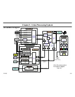
5. Video Processing System
The
Digital Reality Creator (DRC)
is a line doubler and noise reduction
circuit for the 480i signal. The DRC up-converts the 480i signal to a 1080i
signal (High Definition Format). The DRC acts only as a noise reduction
circuit fir the 1080i signal since it is already in a High Definition format.
The
IFP
IC4610 takes the 1080i (from the DRC), 720p, or the 480p
(from the CCP-X IC7701) and performs the Interlace to Progressive scan
conversion, and also performs the signal scaling process to develop a
signal to equal to the resolution of the particular size LCD panels. The IFP
also performs the same process on the sub-picture signal for developing
the picture for the right pane in twin picture display mode, however, the
sub-picture is only at the 480i format resolution level.
The
IFP
IC4610 receives the
PC Input
directly on the DSU-Board. The
IFP is compatible with the VGA, SVGA, XGA, WXGA, and the SXGA
formats at the 60hz vertical frequency rate.
The properly scaled IFP output signal (1080p) on the DSU-Board is sent
to the C-board and the ROOK & LCD Drivers IC’s. The ROOK IC9102
performs gamma control, and white balance control signal processing.
The LCD drivers perform the actual individual pixel control for picture
display. The SXRD panel has the full high-definition resolution of 1920 X
1080.
Summary of Contents for KDS-R60XBR1 - 60" Rear Projection TV
Page 1: ...Models KDS R50XBR1 KDS R60XBR1 Diagnostics and Troubleshooting Course TVP 21 Training Manual ...
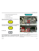
Page 49: ...TVP 21 46 Disassembly Procedures Wire Routing Diagrams Wire Routing Diagrams ...
Page 50: ...TVP 21 47 Disassembly Procedures Wire Routing Diagrams cont ...
Page 51: ...TVP 21 48 Disassembly Procedures Wire Routing Diagrams cont ...
Page 52: ...TVP 21 49 Disassembly Procedures Wire Routing Diagrams cont ...
Page 53: ...TVP 21 50 Disassembly Procedures Wire Routing Diagrams cont ...
Page 58: ...TVP 21 55 Chapter 2 Initial Contact Analysis ...
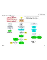
Page 72: ...TVP 21 69 4 Protection Circuits Troubleshooting Flowcharts Flowchart C 1 Figure 4 2 ...
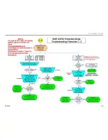
Page 73: ...TVP 21 70 4 Protection Circuits Flowchart C 2 Figure 4 3 ...
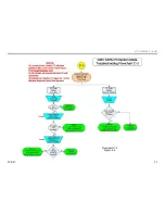
Page 74: ...TVP 21 71 4 Protection Circuits Flowchart C 3 Figure 4 4 ...
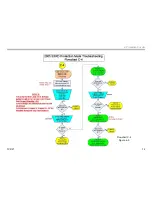
Page 75: ...TVP 21 72 4 Protection Circuits Flowchart C 4 Figure 4 5 ...
Page 88: ...TVP 21 85 5 Video Processing System Video Distortion Flowchart E Figure 5 3 ...
Page 89: ...TVP 21 86 5 Video Processing System Optical Block Flowchart F Figure 5 4 ...
Page 98: ...TVP 21 95 6 Audio Processing System Troubleshooting Flowchart ...
Page 102: ...TVP 21 99 Appendix 2005 SXRD Service Mode Options ...