

TVP-21
64
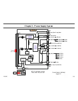
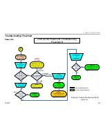
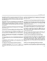
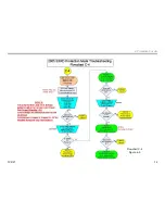
3. Power Supply System
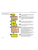
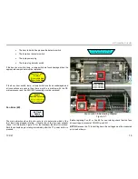
The next step is to confirm application of the AC voltage to the G-Board
through the F-Board (Main Fuse). Check for 110V AC at CN6014 on the
G-Board to confirm AC supply voltage. If the answer to the question
diamond is No (AC is not present at CN6014) then check all connections
between AC power cord and the F-board for loose connections or
damage. Check the main fuse (F6001) on the F-Board. If all connectors
and components are OK replace the F-Board.
Yes
Is AC 110 V
Present
at CN 6014 ?
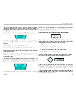
If the answer to the question diamond is Yes (AC is present at CN6014),
then the next step is to check if the Standby 5V power supply is functioning
properly. Check for Standby 5V at CN6502 on G-Board (remove ASU-
Board shields to access CN6502). An alternative Standby 5V checkpoint
is at the Thermostat connector (or directly at the Thermostat) on the left
rear side of the TV (no need to remove any shields).
Yes
Is voltage
5V
Present?
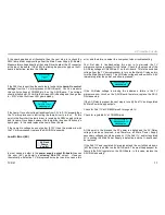
If the Standby 5V is present at the previously mentioned checkpoints
then the Standby 5V power supply is functioning, and there is a possible
microprocessor defect. In this case, replace the DSU-Board.
No
Is voltage
5V
Present?
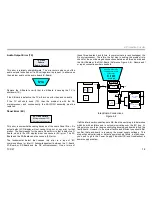
If the Standby 5V is not present at the checkpoints then the Standby 5V
power supply is not functioning. In this case, replace the G-board.
Summary of Contents for KDS-R60XBR1 - 60" Rear Projection TV
Page 1: ...Models KDS R50XBR1 KDS R60XBR1 Diagnostics and Troubleshooting Course TVP 21 Training Manual ...
Page 49: ...TVP 21 46 Disassembly Procedures Wire Routing Diagrams Wire Routing Diagrams ...
Page 50: ...TVP 21 47 Disassembly Procedures Wire Routing Diagrams cont ...
Page 51: ...TVP 21 48 Disassembly Procedures Wire Routing Diagrams cont ...
Page 52: ...TVP 21 49 Disassembly Procedures Wire Routing Diagrams cont ...
Page 53: ...TVP 21 50 Disassembly Procedures Wire Routing Diagrams cont ...
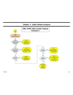
Page 58: ...TVP 21 55 Chapter 2 Initial Contact Analysis ...
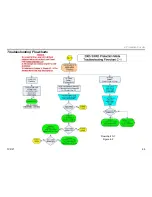
Page 72: ...TVP 21 69 4 Protection Circuits Troubleshooting Flowcharts Flowchart C 1 Figure 4 2 ...
Page 73: ...TVP 21 70 4 Protection Circuits Flowchart C 2 Figure 4 3 ...
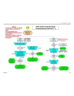
Page 74: ...TVP 21 71 4 Protection Circuits Flowchart C 3 Figure 4 4 ...
Page 75: ...TVP 21 72 4 Protection Circuits Flowchart C 4 Figure 4 5 ...
Page 88: ...TVP 21 85 5 Video Processing System Video Distortion Flowchart E Figure 5 3 ...
Page 89: ...TVP 21 86 5 Video Processing System Optical Block Flowchart F Figure 5 4 ...
Page 98: ...TVP 21 95 6 Audio Processing System Troubleshooting Flowchart ...
Page 102: ...TVP 21 99 Appendix 2005 SXRD Service Mode Options ...