TVP-21
28
Disassembly Procedures
4
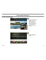
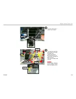
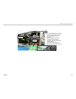
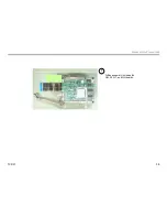
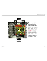
Slide Chassis out until it is stopped
by the vertical bracket. Before
attempting to remove the Chassis
assembly disconnect the wires as
illustrated in the photo.
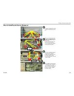
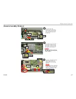
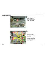
Removal of Complete Chassis Assembly (cont.)
Disconnect
Cables on each side of the
chassis assembly
Disconnect
Fan
connector
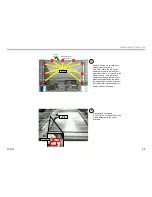
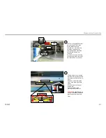
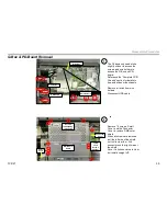
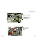
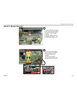
5
Angle the left side of Chassis
assembly out.
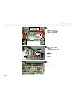
Slide the Chassis to the left (around
the vertical bracket and pull chassis
out.
CAUTION:
Do not remove the vertical
bracket
. This bracket is critical
support for the Upper mirror and
screen block.
Angle out
Slide to
the left
Around
vertical
bracket
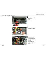
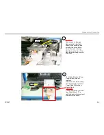
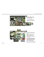
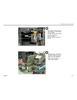
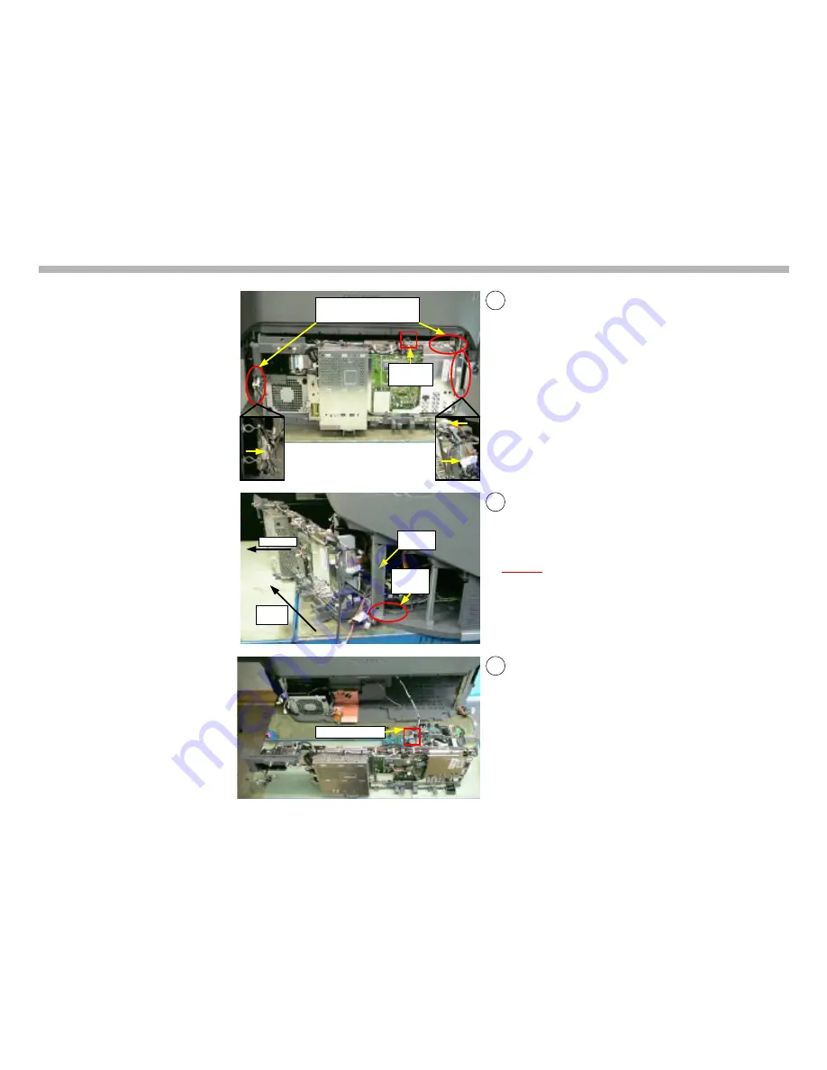
6
Completely remove the Chassis
assembly and disconnect Lamp
Power Supply Block cable.
Power Block cable
Vertical
Bracket
Summary of Contents for KDS-R60XBR1 - 60" Rear Projection TV
Page 1: ...Models KDS R50XBR1 KDS R60XBR1 Diagnostics and Troubleshooting Course TVP 21 Training Manual ...
Page 49: ...TVP 21 46 Disassembly Procedures Wire Routing Diagrams Wire Routing Diagrams ...
Page 50: ...TVP 21 47 Disassembly Procedures Wire Routing Diagrams cont ...
Page 51: ...TVP 21 48 Disassembly Procedures Wire Routing Diagrams cont ...
Page 52: ...TVP 21 49 Disassembly Procedures Wire Routing Diagrams cont ...
Page 53: ...TVP 21 50 Disassembly Procedures Wire Routing Diagrams cont ...
Page 58: ...TVP 21 55 Chapter 2 Initial Contact Analysis ...
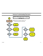
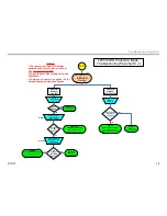
Page 72: ...TVP 21 69 4 Protection Circuits Troubleshooting Flowcharts Flowchart C 1 Figure 4 2 ...
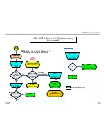
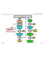
Page 73: ...TVP 21 70 4 Protection Circuits Flowchart C 2 Figure 4 3 ...
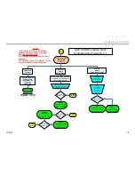
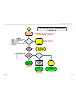
Page 74: ...TVP 21 71 4 Protection Circuits Flowchart C 3 Figure 4 4 ...
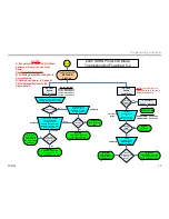
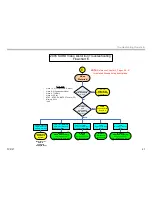
Page 75: ...TVP 21 72 4 Protection Circuits Flowchart C 4 Figure 4 5 ...
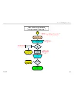
Page 88: ...TVP 21 85 5 Video Processing System Video Distortion Flowchart E Figure 5 3 ...
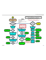
Page 89: ...TVP 21 86 5 Video Processing System Optical Block Flowchart F Figure 5 4 ...
Page 98: ...TVP 21 95 6 Audio Processing System Troubleshooting Flowchart ...
Page 102: ...TVP 21 99 Appendix 2005 SXRD Service Mode Options ...