


TVP-21
17
Troubleshooting Flowcharts
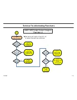
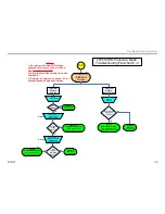
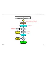
2005 SXRD Protection Mode
Troubleshooting Flowchart C -2
Unit Shuts OFF
RED LED
Flashing
C-2
4X Flash
Pattern
(Fan Rotation )
Check Fan Drive (DR)
and Feedback (FB)
Voltage Levels at
CN2301/pins 6 & 8 (DR)
CN2301/pins 5 & 7 (FB)
*Before Shutdown*
Are (FB)
voltages higher
than 1V?
Replace
The Fan(s)
connected to
the higher than
1V line(s).
Yes
No
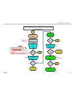
ASU-Board
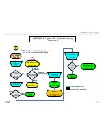
Check rear fans (1 & 4 ) that are
visually accessible
for rotation
Check Fan Drive
Voltage Levels at
CN2301/pins 2 & 11
*Befroe Shutdown*
Are (DR)
voltages
6V?
ASU-Board
Yes
Are fans rotating?
Replaced
Non-Rotating
Fan
Yes
No
Replace
ASU/DSU Assembly
Go to Appendix for
Part # Tables A-1 & A-2
Fan Part Numbers
Fan #1 – 8-835-860-11
Fan #2 – 8-835-859-11
Fan #3 – 8-835-859-11
Fan #4 – 1-787-333-11
Drive
Feedback
No
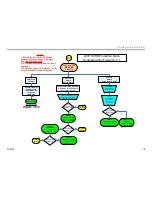
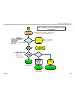
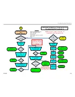
5X Flash
Pattern
Lamp Driver
Check
Supply Voltage
At
X1 Connector
*Before Shutdown*
Is Voltage
380V
Present?
Check
Lamp-ON Voltage
CN2390/pin 4
*Before Shutdown*
Does
voltage go low
3.3V to
0.13V?
Replace
Lamp Power
Supply Block
1-468-936-12
No
Yes
Yes
No
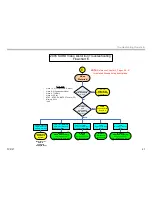
Lamp Driver
Board
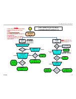
Replace
G-Board
A-1138-898-A
Does
Spark Gap
Light?
3 Attempts
20 Sec. Intervals
Replace LAMP
Lamp Part Number
KDS-R50XBR1 – 9-308-760-0
KDS-R60XBR1 – 9-308-760-0
Yes
No
NOTE: The Lamp Driver is
also referred to as the Lamp
Power Supply Block
ASU-Board
Replace
ASU/DSU Assembly
Go to Appendix for
Part # Tables A-1 & A-2
Replace
ASU/DSU Assembly
Go to Appendix for
Part # Tables A-1 & A-2
NOTES:
1) Except for the Lamp LED all flash
patterns will occur on the Front
Panel
Red Power/Standby LED
2) All voltage are measured prior to
unit shutdown
3) Reference Chapter 4, Pages 43 -
52 for detailed flowchart step
descriptions
Summary of Contents for KDS-R60XBR1 - 60" Rear Projection TV
Page 1: ...Models KDS R50XBR1 KDS R60XBR1 Diagnostics and Troubleshooting Course TVP 21 Training Manual ...
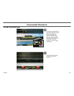
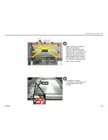
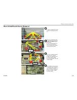
Page 49: ...TVP 21 46 Disassembly Procedures Wire Routing Diagrams Wire Routing Diagrams ...
Page 50: ...TVP 21 47 Disassembly Procedures Wire Routing Diagrams cont ...
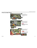
Page 51: ...TVP 21 48 Disassembly Procedures Wire Routing Diagrams cont ...
Page 52: ...TVP 21 49 Disassembly Procedures Wire Routing Diagrams cont ...
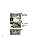
Page 53: ...TVP 21 50 Disassembly Procedures Wire Routing Diagrams cont ...
Page 58: ...TVP 21 55 Chapter 2 Initial Contact Analysis ...
Page 72: ...TVP 21 69 4 Protection Circuits Troubleshooting Flowcharts Flowchart C 1 Figure 4 2 ...
Page 73: ...TVP 21 70 4 Protection Circuits Flowchart C 2 Figure 4 3 ...
Page 74: ...TVP 21 71 4 Protection Circuits Flowchart C 3 Figure 4 4 ...
Page 75: ...TVP 21 72 4 Protection Circuits Flowchart C 4 Figure 4 5 ...
Page 88: ...TVP 21 85 5 Video Processing System Video Distortion Flowchart E Figure 5 3 ...
Page 89: ...TVP 21 86 5 Video Processing System Optical Block Flowchart F Figure 5 4 ...
Page 98: ...TVP 21 95 6 Audio Processing System Troubleshooting Flowchart ...
Page 102: ...TVP 21 99 Appendix 2005 SXRD Service Mode Options ...