


TVP-21
73
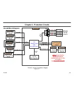
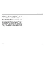
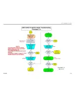
4. Protection Circuits
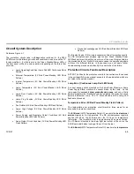
Troubleshooting Flowchart Step Descriptions
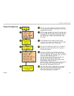
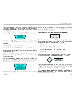
Lamp Error (Lamp LED)
LAMP LED
Flashing
In most cases a flashing Lamp LED indicates a defective Lamp, and the
Lamp must be replaced. However, an open circuit in the high-voltage
cabling to the lamp will also case this failure indication. Therefore, before
replacing the lamp confirm that the cabling and connections are good
between the Lamp Drive board and the lamp.
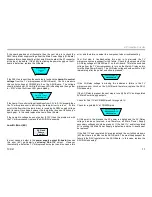
Temperature Error (2X)
2X Flash
Pattern
(Temperature )
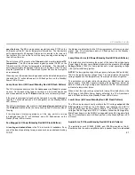
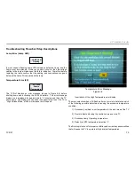
The TV first displays an error message (shown in Figure 4-6) before
shutting down and activating the 2X flash pattern. The error message
dialog box is displayed for approximately 1.5 minutes and then the TV
shuts down. The dialog give the owner the oppurtunity to set the TV to
“High Altitude Mode,” which will increase the fan speed.
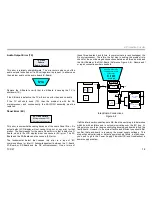
Insert photo of the High Temperature error display
The main objective when a 2X flash pattern occurs is to determine which
of the following possible defects are causing the excessive temperature
condition.
1) Excessively ambient room temperature in the local area of the TV
2) Dust or objects blocking the ventilation areas on the TV
3)
Excessive Lamp Operating temperature
4) Defective LM75 temperature detection IC
The first step is to check for proper ventilation and correct any abnormalities
that will cause the TV to operate at high internal temperatures.
Temperature Error Message
Figure 4-6
Summary of Contents for KDS-R60XBR1 - 60" Rear Projection TV
Page 1: ...Models KDS R50XBR1 KDS R60XBR1 Diagnostics and Troubleshooting Course TVP 21 Training Manual ...
Page 49: ...TVP 21 46 Disassembly Procedures Wire Routing Diagrams Wire Routing Diagrams ...
Page 50: ...TVP 21 47 Disassembly Procedures Wire Routing Diagrams cont ...
Page 51: ...TVP 21 48 Disassembly Procedures Wire Routing Diagrams cont ...
Page 52: ...TVP 21 49 Disassembly Procedures Wire Routing Diagrams cont ...
Page 53: ...TVP 21 50 Disassembly Procedures Wire Routing Diagrams cont ...
Page 58: ...TVP 21 55 Chapter 2 Initial Contact Analysis ...
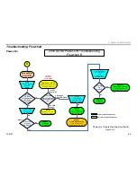
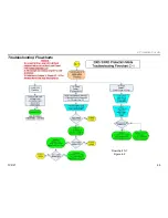
Page 72: ...TVP 21 69 4 Protection Circuits Troubleshooting Flowcharts Flowchart C 1 Figure 4 2 ...
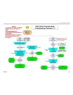
Page 73: ...TVP 21 70 4 Protection Circuits Flowchart C 2 Figure 4 3 ...
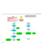
Page 74: ...TVP 21 71 4 Protection Circuits Flowchart C 3 Figure 4 4 ...
Page 75: ...TVP 21 72 4 Protection Circuits Flowchart C 4 Figure 4 5 ...
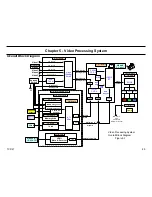
Page 88: ...TVP 21 85 5 Video Processing System Video Distortion Flowchart E Figure 5 3 ...
Page 89: ...TVP 21 86 5 Video Processing System Optical Block Flowchart F Figure 5 4 ...
Page 98: ...TVP 21 95 6 Audio Processing System Troubleshooting Flowchart ...
Page 102: ...TVP 21 99 Appendix 2005 SXRD Service Mode Options ...