


TVP-21
53
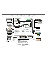
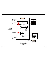
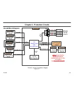
1. Overall System Block
DSU-Board (Video Processing)
The circuits located on the DSU-Board perform all video processing
functions. It is the WEGA engine. The following circuits are included on
the board.
•
Composite/Component Processor (CCP)
•
Digital Reality Creator (DRC)
•
Image Format Processor (IFP)
•
TV Microprocessor
•
WE Microprocessor (part of the IFP)
AK-Board (Audio Output Processing)
The AK-Board (audio) takes the Sony/Phillips Digital Interface signal from
the DSP on the ASU-Board and converts it to an IIS (PCM) signal for
processing on the K-Board (audio).
K-board (Audio Output Amplifier System)
The K-Board is the S-Master digital audio amplifier system. It takes the
IIS from the AK-Board and converts it to a PWM signal. The PWM signal
is then amplified and low-pass filtered to develop the output analog audio
signal.
Digital Module Block (DMB)
The term Digital Module Block (or DMB) is used to describe the shielded
area that includes the Q-Box module and PD-Board (HDMI). However,
the Q-Box module and PD-Board are separate and individual parts as
described below.
Q-Box Module
The Q-Box module includes the QM, QH, QI, and QT boards and performs
the following functions.
•
ASTC Signal Processing and Control
•
CableCard Processing and Control
•
ATI Microprocessor
o
The ATI microprocessor becomes the Main microprocessor
(the TV Micro on the DSU-Board is the standby micro) after
initial power on. All user settings are store in an EEPROM
in the Q-Box module.
•
Memory Stick Signal Processing and Control
•
i-Link Signal Processing and Control
PD-Board
The PD-Board performs all High Definition Media Interface (HDMI) &
Digital Visual Interface (DVI) signal processing functions (a DVI-to-HDMI
adapter is needed to input a DVI signal).
Optical Block
The Optical Block includes the C-Board, prisms, mirrors, SXRD panels
and lenses necessary to process and modulate the lamp light and display
the video information on the screen.
C-Board
The C-Board circuits perform the following primary functions.
•
Gamma Correction
•
White Balance Correction
•
SXRD Panel Drive
Summary of Contents for KDS-R60XBR1 - 60" Rear Projection TV
Page 1: ...Models KDS R50XBR1 KDS R60XBR1 Diagnostics and Troubleshooting Course TVP 21 Training Manual ...
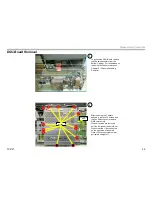
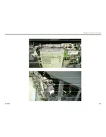
Page 49: ...TVP 21 46 Disassembly Procedures Wire Routing Diagrams Wire Routing Diagrams ...
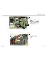
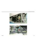
Page 50: ...TVP 21 47 Disassembly Procedures Wire Routing Diagrams cont ...
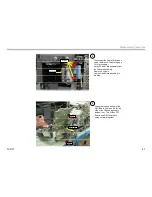
Page 51: ...TVP 21 48 Disassembly Procedures Wire Routing Diagrams cont ...
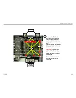
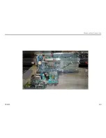
Page 52: ...TVP 21 49 Disassembly Procedures Wire Routing Diagrams cont ...
Page 53: ...TVP 21 50 Disassembly Procedures Wire Routing Diagrams cont ...
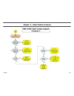
Page 58: ...TVP 21 55 Chapter 2 Initial Contact Analysis ...
Page 72: ...TVP 21 69 4 Protection Circuits Troubleshooting Flowcharts Flowchart C 1 Figure 4 2 ...
Page 73: ...TVP 21 70 4 Protection Circuits Flowchart C 2 Figure 4 3 ...
Page 74: ...TVP 21 71 4 Protection Circuits Flowchart C 3 Figure 4 4 ...
Page 75: ...TVP 21 72 4 Protection Circuits Flowchart C 4 Figure 4 5 ...
Page 88: ...TVP 21 85 5 Video Processing System Video Distortion Flowchart E Figure 5 3 ...
Page 89: ...TVP 21 86 5 Video Processing System Optical Block Flowchart F Figure 5 4 ...
Page 98: ...TVP 21 95 6 Audio Processing System Troubleshooting Flowchart ...
Page 102: ...TVP 21 99 Appendix 2005 SXRD Service Mode Options ...