


TVP-21
1
Technologies & Features
Technology
Silicon Crystal Reflective Display (SXRD)
SXRD is Sony’s adaptation of Liquid Crystal on Silicon (LCoS) micro-
display technology. The SXRD technology is similar to the LCD
technology use in previous rear projection and direct TV products in that
is uses liquid crystal materials to pass and block light to form the picture
you see, however, this is where the similarities stop.
The primary differences between SXRD and the standard LCD
technologies are as follows.
LCD Technology
o
Is a transmissive device – light is directed into the rear
of the panel, the passes through the panel and the liquid
crystal material. The light only passes through the liquid
crystal material once. The liquid crystals modulate the
light as it passes through the panel.
o
The liquid crystals when layered from a 90-degree
angular orientation after so many layers. Therefore, light
is completely passed when no potential is applied to the
liquid crystals.
o
The Panel depth is thicker then the SXRD technology
because the LCD drives and liquid crystal material are
place on separate layers in the panel.
o
The distance between the pixels is greater than the SXRD
technology (causing the screen-door effect) because the
matrix wiring and switching elements must be covered
with a solid plastic grid structure.
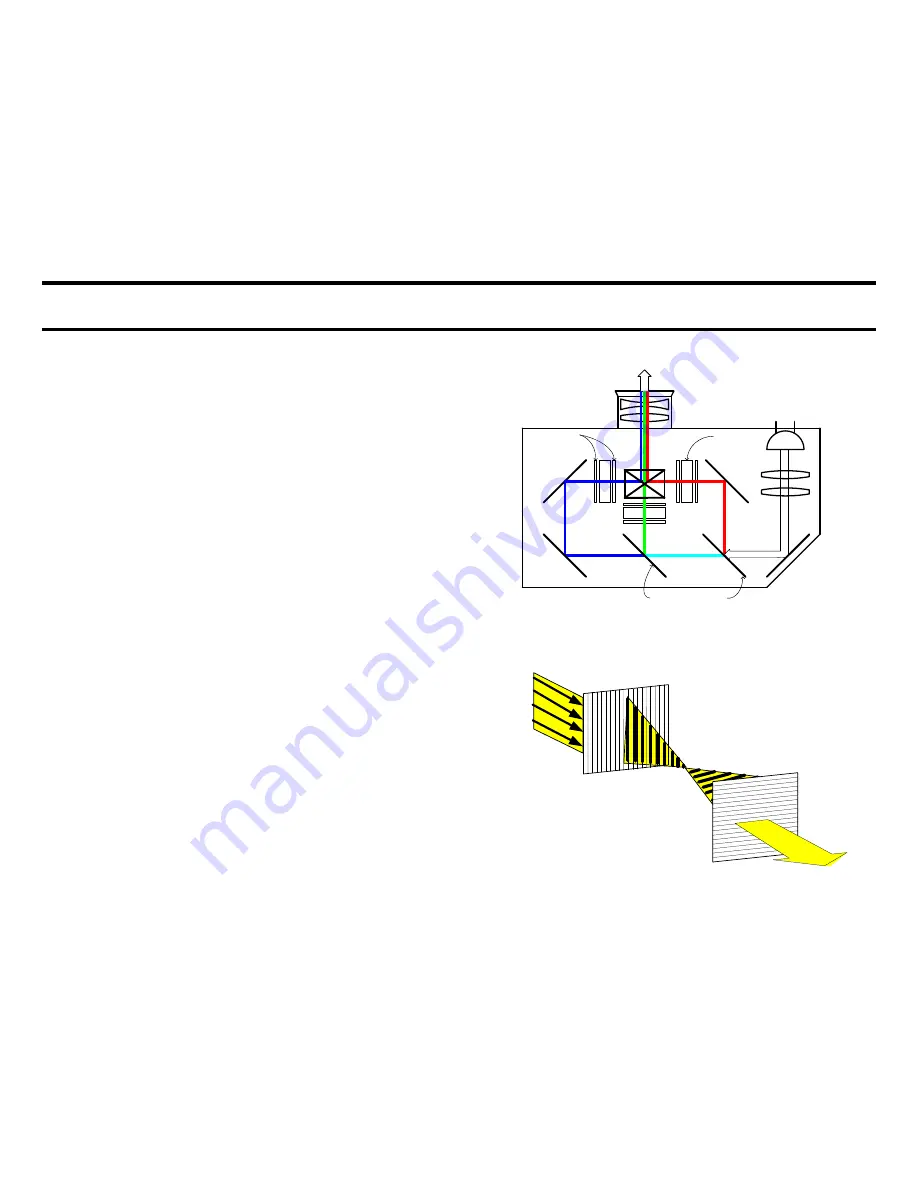
DICHROIC MIRRORS
LAMP
TO MIRROR
POLARIZERS
LCD PANEL
LCD Optics Block
Backlight
Source
LCD Natural Layering Light Effect
Summary of Contents for KDS-R60XBR1 - 60" Rear Projection TV
Page 1: ...Models KDS R50XBR1 KDS R60XBR1 Diagnostics and Troubleshooting Course TVP 21 Training Manual ...
Page 49: ...TVP 21 46 Disassembly Procedures Wire Routing Diagrams Wire Routing Diagrams ...
Page 50: ...TVP 21 47 Disassembly Procedures Wire Routing Diagrams cont ...
Page 51: ...TVP 21 48 Disassembly Procedures Wire Routing Diagrams cont ...
Page 52: ...TVP 21 49 Disassembly Procedures Wire Routing Diagrams cont ...
Page 53: ...TVP 21 50 Disassembly Procedures Wire Routing Diagrams cont ...
Page 58: ...TVP 21 55 Chapter 2 Initial Contact Analysis ...
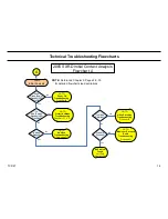
Page 72: ...TVP 21 69 4 Protection Circuits Troubleshooting Flowcharts Flowchart C 1 Figure 4 2 ...
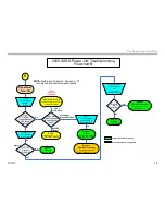
Page 73: ...TVP 21 70 4 Protection Circuits Flowchart C 2 Figure 4 3 ...
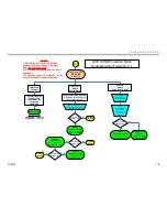
Page 74: ...TVP 21 71 4 Protection Circuits Flowchart C 3 Figure 4 4 ...
Page 75: ...TVP 21 72 4 Protection Circuits Flowchart C 4 Figure 4 5 ...
Page 88: ...TVP 21 85 5 Video Processing System Video Distortion Flowchart E Figure 5 3 ...
Page 89: ...TVP 21 86 5 Video Processing System Optical Block Flowchart F Figure 5 4 ...
Page 98: ...TVP 21 95 6 Audio Processing System Troubleshooting Flowchart ...
Page 102: ...TVP 21 99 Appendix 2005 SXRD Service Mode Options ...