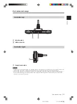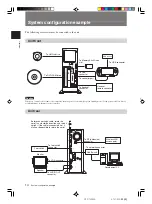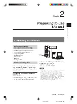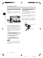
Overview
12
DTP-T2000A 4-121-350-
11(1)
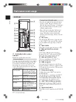
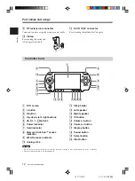
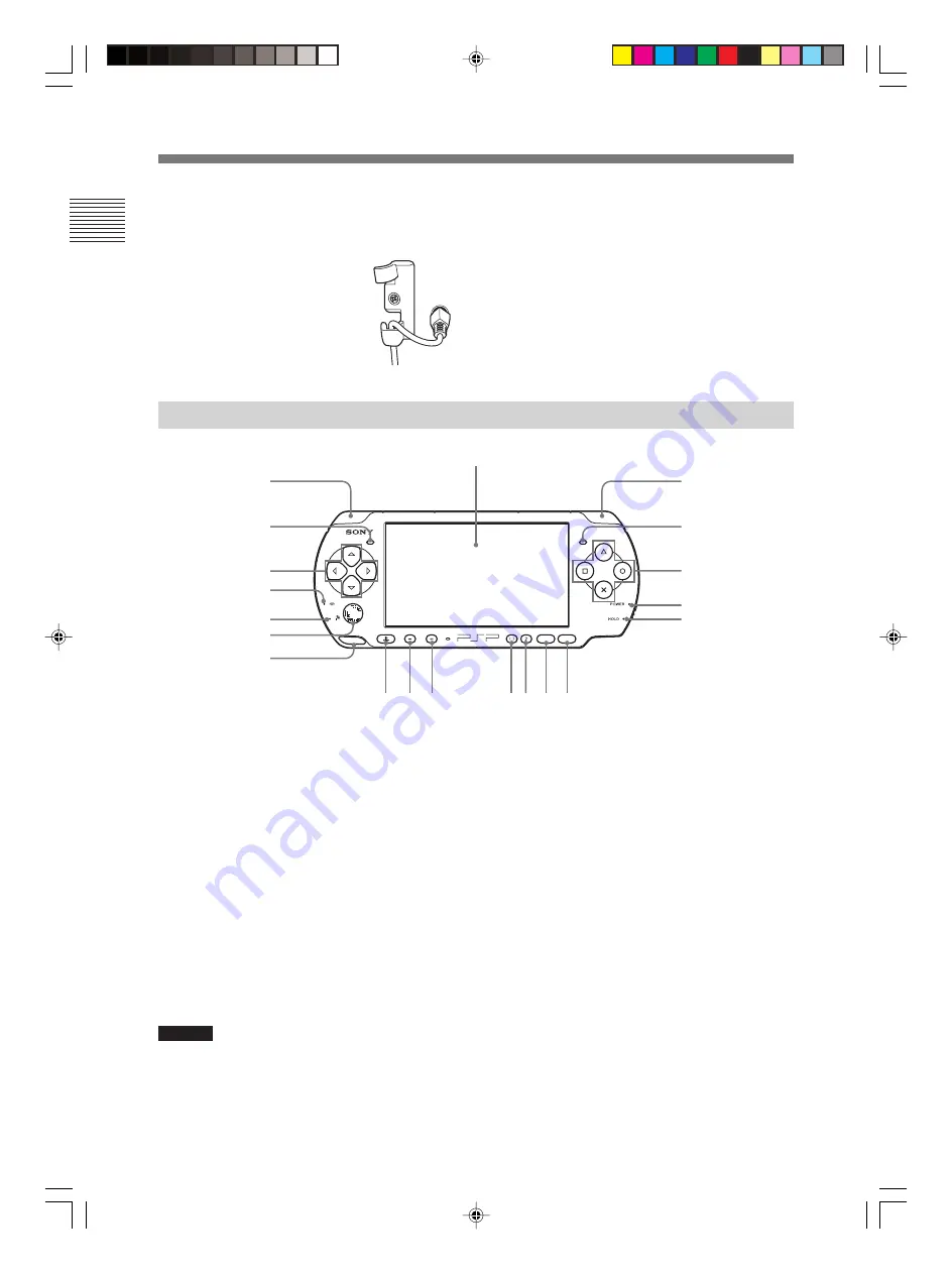
Controller front
1
LCD screen
2
L button
3
R button
4
Up, down, left, right buttons
5
△
△
△
△
△
,
○
○
○
○
○
,
×
,
□
□
□
□
□
buttons
6
Power indicator
7
Hold indicator
8
Memory Stick Duo
TM
access
indicator
9
WLAN access indicator
q;
Analog stick
SELECT
START
VOL
qa
Strap holder
qs
Left speaker
qd
Right speaker
qf
PS button
qg
Volume - button
qh
Volume
+
button
qj
Display button
qk
Sound button
ql
Select button
w;
Start button
2
4
8
9
q;
qa
qs
1
qf qg qh
qjqkqlw;
3
5
6
7
qd
Part names and usage
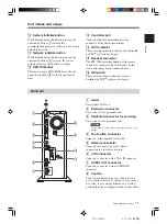
9
RF (extension) connector
Connects to an access point using a coaxial cable.
q;
Clamp
For securing the aerial and
AC adaptor to the unit.
qa
DC IN 19.5V connector
For attaching the included AC adaptor.
Part names and usage
Caution
• Do not cover or insert foreign objects into the speakers as doing so may result in damage to the controller.
• The microphone feature is not implemented.

