– 4 –
DSC-P71/P71M
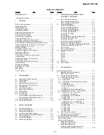
Section
Title
Page
*
The color reproduction frame is shown on page 201.
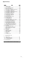
3.
Flange Back Check ....................................................... 5-17
4.
F No. Compensation ...................................................... 5-18
5.
Mechanical Shutter Adjustment .................................... 5-18
6.
Light Value Adjustment ................................................. 5-19
7.
Mixed Color Cancel Adjustment .................................... 5-19
8.
Auto White Balance 3200K Standard Data Input ......... 5-20
9.
Auto White Balance 3200K Check 1 ............................. 5-21
10. Auto White Balance 3200K Check 2 ............................. 5-22
11. Auto White Balance 5800K Standard Data Input ......... 5-23
12. Auto White Balance 5800K Check 1 ............................. 5-24
13. Auto White Balance 5800K Check 2 ............................. 5-25
14. Color Reproduction Adjustment .................................... 5-26
15. CCD White Defect Compensation ................................ 5-27
16. CCD Black Defect Compensation ................................. 5-28
17. CCD Linearity Check ..................................................... 5-29
18. Strobe White Balance Adjustment ................................ 5-30
19. AF Illumination Check ................................................... 5-32
1-5.
LCD System Adjustments ............................................. 5-33
1.
LCD Initial Data Input (1) .............................................. 5-34
2.
LCD Initial Data Input (2) .............................................. 5-34
3.
Backlight Current Adjustment (PK-064 Board) ............. 5-35
4.
VCO Adjustment (PK-064 Board) ................................. 5-35
5.
PSIG Gray Adjustment (PK-064 Board) ....................... 5-36
6.
D Range Adjustment (PK-064 Board) .......................... 5-36
7.
Black Limit Adjustment (PK-064 Board) ....................... 5-37
8.
Contrast Adjustment (PK-064 Board) ........................... 5-37
9.
Center Voltage Adjustment (PK-064 Board) ................. 5-38
10. V-COM DC Adjustment (PK-064 Board) ....................... 5-38
11. White Balance Adjustment (PK-064 Board) ................. 5-39
5-2.
Service Mode ................................................................ 5-40
2-1.
Adjusting Remote Commander ..................................... 5-40
1.
Used the Adjusting Remote Commander ..................... 5-40
2.
Precautions upon Using the Adjusting
Remote Commander ..................................................... 5-40
2-2.
Data Process ................................................................. 5-41
2-3.
Service Mode ................................................................ 5-42
1.
Setting the Test Mode .................................................... 5-42
2.
Bit Value Discrimination ................................................ 5-42
3.
Switch Check (1) ........................................................... 5-42
4.
Switch Check (2) ........................................................... 5-43
5.
LED Check .................................................................... 5-43
6.
Self Diagnosis Code ...................................................... 5-43
6.
REPAIR PARTS LIST
6-1.
Exploded Views ............................................................. 6-1
6-1-1. Cabinet (Front) Section ............................................ 6-1
6-1-2. Cabinet (Rear) Assembly ......................................... 6-2
6-1-3. Lens Block Assembly ............................................... 6-3
6-2.
Electrical Parts List ....................................................... 6-4


