5-27
DSC-P71/P71M
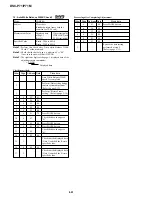
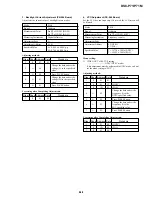
15. CCD White Defect Compensation
RadarW
RadarW
RadarW
RadarW
RadarW
Mode
CAMERA
Subject
Not required
Measurement Point
Displayed data of page: 6,
address: 55
Measuring Instrument
Adjusting remote commander
Note 1:
Check that the data of page: 6, address: 02 is “00”.
If not, turn the power of unit OFF/ON.
Note 2:
The“CCD White Defect Compensation” should be made
when the set warms up at certain duration after the power
was turned on, as it is affected with the temperature.
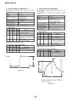
Adjusting method:
Order Page Address Data
Procedure
1
Perform “Data setting during
camera system adjustment”.
(Refer to page 5-13)
2
E
64
Note down the data.
3
E
64
1E
Press PAUSE button.
4
E
69
Note down the data.
5
E
69
0A
Press PAUSE button.
6
6
01
8B
Press PAUSE button.
7
6
02
Check the data changes to
“01”.
8
6
55
Check the data.
00 to 7F: Normal
80 to FF: Defective
9
6
01
00
Press PAUSE button.
10
E
64
0F
Press PAUSE button.
11
E
69
60
Press PAUSE button.
12
6
01
87
Press PAUSE button.
13
6
02
Check the data changes to
“01”.
14
6
55
Check the data.
00: Normal
01 to FF: Defective
Processing after Completing Adjustment:
Order Page Address Data
Procedure
1
6
01
00
Press PAUSE button.
2
E
64
Set data noted down at step
2, and press PAUSE button.
3
E
69
Set data noted down at step
4, and press PAUSE button.
4
Release the data setting
performed at step 1.
(Refer to page 5-13)


