Chapter 1
Overview
14
Chapter 1
Overview
⁄
SCSI
FLASH
MONITOR
REMOTE
CAMERA
MODE SELECT
SCSI In
AC IN
SCSI Out
VIDEO
S-VIDEO
R
G
B
SYNC
FS
RS-232C
Location and Function of Parts
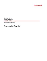
Rear panel
1
MODE SELECT switches
These eight DIP switches select the SCSI ID of the
digital processor, the attenuation compensation setting
for the camera cable, and other settings.
For details of the settings of these switches, see the section
“Setting the DIP Switches” on page 50.
2
SCSI In and SCSI Out connectors (50-pin, high-
density)
Use these to connect to other SCSI devices (computer,
printer, and so forth).
For details of the SCSI connections, see the section “SCSI
Connections” on page 48.
3
FLASH connector (X-contact socket)
Connect the cable from a flash unit.
This connector is not used when the cable from the
flash unit is connected to the FLASH connector on the
camera head.
4
⁄
AC IN connector
Use the supplied power cord to connect to a 120 V AC
(NTSC model) or 220 to 240 V AC (PAL model)
power outlet.
5
CAMERA connector (26-pin, female)
Connect this to the PROCESSOR connector of the
camera head with the supplied camera cable.
6
REMOTE RS-232C connector (D-sub 9-pin,
female)
(Undefined.)
7
REMOTE FS (foot switch) connector (mini-
jack)
Connect the cable from a foot switch.
1
MODE SELECT switches
2
SCSI In and SCSI Out connectors
3
FLASH connector
4
⁄
AC IN connector
5
CAMERA connector
6
REMOTE RS-232C connector
7
REMOTE FS connector
8
MONITOR connectors