Sony Digital betacam DVW-707 Maintenance Manual Download Page 194

4-110

DVW-790WS/709WS/707 P2V1

DVW-790WSP/709WSP/707P P2V1

4-2. Parts Replacement
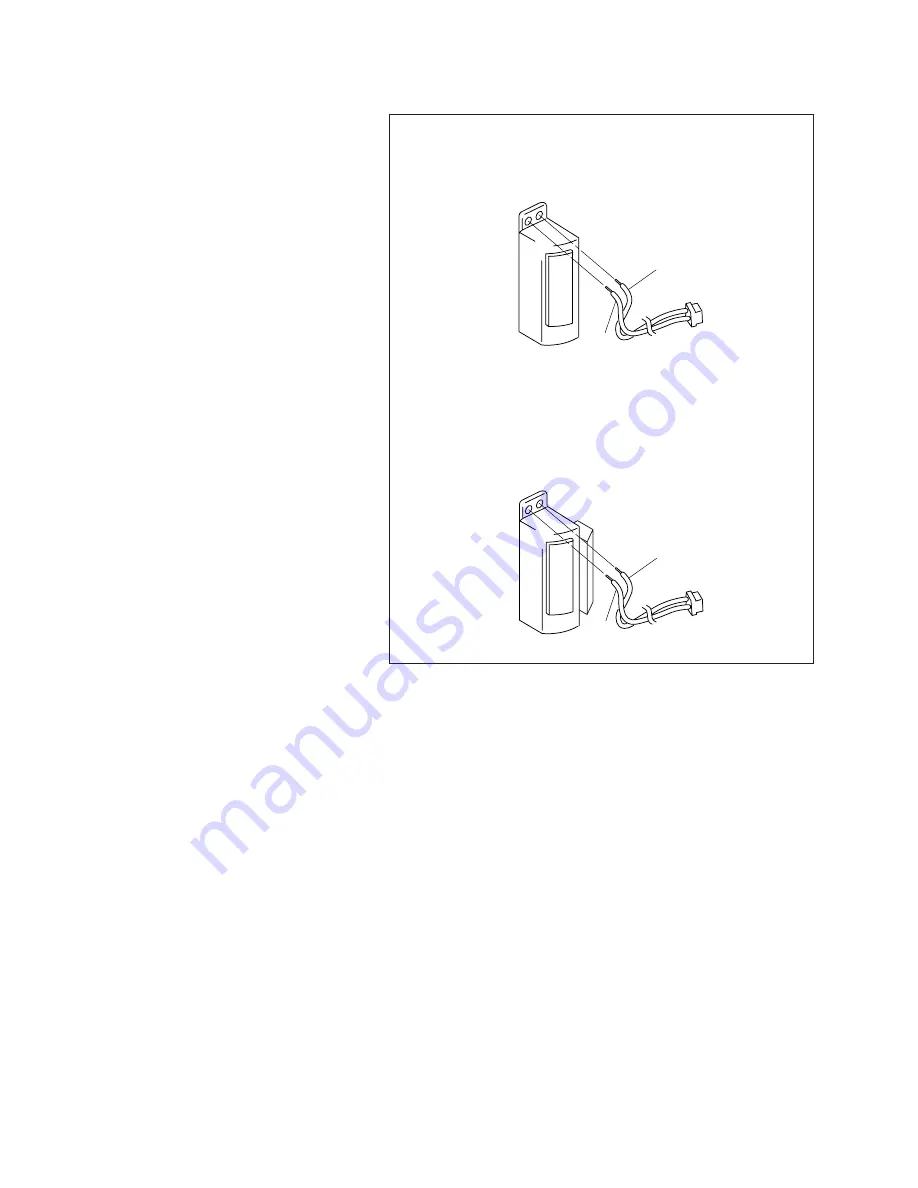
3. Harness Removal

Desolder and remove the harness.

4. Harness Soldering

Attach the harness removed at step 3 with solder to

the new FE head.

DVW-707:

10001 through 10055

DVW-707P:

40001 through 40190

DVW-709WS: 10001 through 10125

DVW-709WSP: 40001 through 40255

DVW-790WS: 10001 through 10160

DVW-790WSP: 40001 through 40510

BLK

GRY

BLK

GRY

DVW-707:

10056 and higher

DVW-707P:

40191 and higher

DVW-709WS: 10126 and higher

DVW-709WSP: 40256 and higher

DVW-790WS: 10161 and higher

DVW-790WSP: 40511 and higher

Summary of Contents for Digital betacam DVW-707

Page 1: ...L BETACAM CAMCORDER DVW 707 707P DVW 709WS 709WSP DVW 790WS 790WSP SDI OUTPUT BOARD BKDW 702 PICTURE CACHE BOARD BKDW 703 IMAGE INVERTER BOARD BKDW 704 MAINTENANCE MANUAL Part 2 Volume 1 1st Edition Revised 1 ...

Page 2: ...nal bestimmt Alle Wartungsarbeiten dürfen nur von qualifiziertem Fachpersonal ausgeführt werden Um die Gefahr eines elektrischen Schlages Feuergefahr und Verletzungen zu vermeiden sind bei Wartungsarbeiten strikt die Angaben in der Anleitung zu befolgen Andere als die angegeben Wartungsarbeiten dürfen nur von Personen ausgeführt werden die eine spezielle Befähigung dazu besitzen AVERTISSEMENT Ce m...

Page 3: ...everandøren For the customers in the U S A and Canada RECYCLING NICKEL CADMIUM BATTERIES Nickel Cadmium batteries are recyclable You can help preserve our environment by returning your unwanted batteries to your nearest point for collection recycling or proper disposal Note In some areas the disposal of nickel cadmium batteries in household or business trash may be prohibited RBRC Rechargeable Bat...

Page 4: ......

Page 5: ...re CCD Units 1 9 1 5 2 Description on CCD Block Number 1 9 1 6 Description on EEPROM NV RAM Data 1 9 1 7 Note on the DCP 17 Board Replacement 1 10 1 8 EEPROM on the ES 23 Board 1 10 1 9 Note on the IF 716 Board Replacement 1 11 1 10 Note on the RE 160 and RE 161 Boards 1 11 1 11 DC Fans Precaution 1 11 1 12 Setting Adjusting After Board Replacements 1 11 2 Setup Menu 2 1 Service Mode 2 1 2 1 1 Fun...

Page 6: ... Adjustment 4 1 4 1 1 Notes 4 1 4 1 2 Threading End Unthreading End Mode 4 2 4 1 3 Manual Eject Assembly Removal Installation 4 3 4 2 Parts Replacement 4 4 4 2 1 Upper Drum Assembly Replacement 4 7 4 2 2 Brush Assembly Replacement for Slip Ring 4 17 4 2 3 Slip Ring Assembly Replacement 4 20 4 2 4 Drum Assembly Replacement 4 24 4 2 5 Pinch Roller Replacement 4 30 4 2 6 HC Roller Assembly Replacemen...

Page 7: ...ment 5 18 5 5 CUE Head Height Adjustment 5 20 5 6 CUE Head Azimuth Check 5 23 5 7 CUE Head Head to tape Contact Adjustment 5 25 5 8 CUE TC Head Position Adjustment 5 27 5 9 CUE Output Level Check 5 30 6 VTR System Alignment 6 1 Preparation 6 1 6 2 Power System Adjustment 6 2 6 2 1 Battery End Detection Voltage Adjustment 6 2 6 3 Servo System Adjustment 6 3 6 3 1 Automatic Servo Adjustment 6 3 6 3 ...

Page 8: ...mma Correction Adjustment 7 17 7 13 Black Set Adjustment 7 18 7 14 Flare Adjustment 7 19 7 15 Knee and White Clip Adjustments 7 20 7 15 1 Manual Knee and White Clip Adjustments 7 20 7 15 2 DCC Pre Knee Adjustment 7 21 7 15 3 DCC Knee Adjustment 7 22 7 16 Detail Signal Adjustment 16 9 7 23 7 16 1 Crispening Adjustment 16 9 7 23 7 16 2 Level Depandent Adjustment 16 9 7 23 7 16 3 Detail Frequency Adj...

Page 9: ...8 R B AD Gain Adjustment 8 10 8 9 VA Gain Adjustment 8 11 8 10 Preset White Adjustment 8 12 8 11 Shading Adjustment 8 12 8 11 1 Black Shading Adjustment 8 12 8 11 2 White Shading Adjustment 8 13 8 12 Gamma Correction Adjustment 8 14 8 13 Black Set Adjustment 8 15 8 14 Flare Adjustment 8 15 8 15 Knee and White Clip Adjustments 8 16 8 15 1 Manual Knee and White Clip Adjustments 8 16 8 15 2 DCC Pre K...

Page 10: ......

Page 11: ...ion 1 Service Overview Explains the fixtures using the extension boards and precautions for board part replacement Section 2 Maintenance Mode Explains the setup menu service mode of this unit Section 3 Parts Replacement Explains the replacement of the boards CCD unit and external connectors switches Section 4 Mechanical Deck Parts Replacement Explains the replacement of the parts of the mechanical...

Page 12: ...r the unit Section 5 Board Layouts Describes the board layouts for the unit Related manuals Besides this Maintenance Manual Part 2 the following manuals are available for this unit Operation Manual Supplied with this unit This manual is necessary for application and operation of this unit Maintenance Manual Part 1 Supplied with this unit This manual provides the information that is required to the...

Page 13: ...ty Gauge 3 Drum eccentricity adjustment 3 J 6001 830 A Drum Eccentricity Gauge 2 4 J 6026 110 A Multi Burst Chart Camera adjustment J 6026 130 B Gray Scale Chart transparent type 4 3 Commercially Gray Scale Chart reflective type 4 3 available J 6394 080 A Gray Scale Chart transparent type 16 9 5 J 6029 140 B Pattern Box PTB 500 6 J 6035 070 A IC External Tool CT 2101 Extraction of IC PLCC type 7 J...

Page 14: ...ning screws J 6325 380 A Torque Driver Bit for M2 J 6325 400 A Torque Driver for 3 kg J 6325 530 A Drum Eccentricity Gauge 6 Drum eccentricity adjustment J 6326 120 A Hexagonal Bit 1 5 mm Tightening screws J 6420 840 A Channel Condition Checker REC current adjustment J 6420 900 A MB Translate Board HN board operation check J 6420 910 A TP Tool TP harness for tape path adjustment J 6420 930 A Exten...

Page 15: ...ideo tracking adjustment NTSC 8 960 073 51 Alignment Tape ZR5 1P Digital video audio adjustment PAL 8 960 073 61 Alignment Tape ZR2 1P Video tracking adjustment PAL 9 919 573 01 Cleaning Fluid TTP cleaning __ Commercially Digital Betacam Video Cassette For recording available BCT D6 D12 D22 D32 D40 Cleaning Tape BCT D12CL Cleaning video heads 1 1 2 Adjustment Equipment Equipment Model Name Remarks...

Page 16: ...on board Reference checked DCP board assembly side A EX 655 and EX 656 Section 1 2 1 side B EX 657 Section 1 2 2 DVP board assembly side A EX 655 and EX 656 Section 1 2 1 side B EX 658 Section 1 2 2 SV 210 board EX 667 Section 1 2 3 DC DC converter DIF 75 board BKDW 702 1 2 1 Using the EX 655 and EX 656 Boards The EX 655 and EX 656 boards are always connected and used in a pair To check adjust the...

Page 17: ...e boards are intended for the following use EX 657 board For the side B of DCP board assembly check EX 658 board For the side B of DVP board assembly check Procedure 1 Pull the DCP and DVP board assemblies out 2 Insert the EX 657 board into the slot for the DCP board assembly 3 Insert the EX 658 board into the slot for the DVP board assembly 4 Connect the DCP board assembly to the EX 657 board 5 C...

Page 18: ...g the EX 667 Board The EX 667 board is intended for check of the following boards part SV 210 Board DC DC Converter DIF 75 Board BKDW 702 n The coaxial cable fixed on the EX 667 board is used for extending the DIF 75 board SV 210 Board 1 Pull the SV 210 Board out 2 Insert the EX 667 board into the slot and then push it to connect the MB 811 board 3 Connect the SV 210 board to the EX 667 board MB 8...

Page 19: ... coaxial cable from the connector CN2 on the EX 667 board 3 Insert the EX 667 board into the slot and then push it to connect to the MB 811 board 4 Reconnect the coaxial cable disconnected in step 1 to the connector CN2 on the EX 667 board 5 Engage the DIF 75 board to the EX 667 board 6 Connect the coaxial cable disconnected from the EX 667 board in step 2 to the connector CN2 on the DIF 75 board ...

Page 20: ...to the connector with the conductive surface silver side down n Be sure to insert the wire straightforward 3 Slide portions A in the reverse direction to lock the connector 1 4 IC Link w The IC link is critical for safe operation To avoid danger of a fire or electric shock be sure use the specified component as a spare part when replacing it c Replacement of the IC link of the plugged in unit may ...

Page 21: ...on 3 2 1 Replacing the CCD Unit 1 6 Description on EEPROM NV RAM Data The table below gives the stored data of EEPROMs NV RAM on the printed circuit boards Board Ref No EEPROM NV RAM Stored data Reference DCP 17 IC152 C3 NV RAM All value of setup menu Section 1 7 IC140 D5 EEPROM Special gamma table data Section 1 7 ES 23 IC18 B2 EEPROM Board adjustment data Section 1 8 IF 716 IC102 D4 EEPROM Model...

Page 22: ...Board Section 7 1 or 8 2 Camera System Electrical Adjust ments 1 For DVW 790WS 790WSP 709WS 709WSP only 2 For DVW 707 707P only 1 7 Note on the DCP 17 Board Replacement 1 8 EEPROM on the ES 23 Board 1 8 EEPROM on the ES 23 Board c Operation of the unit elevates the temperature of the IC package Heated IC package may result in injury Replace the IC after turning off the power and ample time for the...

Page 23: ...t CCD unit 5 1 Tape Path Alignment 7 2 8 2 VCO CONT Frequecy Check 7 3 8 3 AD Clock Phase Adjustment MM P1 1 Section 4 5 Camera Sysytem Electrical Alignment 1 Maintenance Manual Part 1 2 For DVW 707 707P only 3 For DVW 790WS 790WSP 709WS 709WSP only 1 9 Note on the IF 716 Board Replacement c Operation of the unit elevates the temperature of the IC package Heated IC package may result in injury Rep...

Page 24: ......

Page 25: ...tems whose set values cannot be changed or to which set values are not reflected Refer to Section 2 1 3 Setup Menu List for details How to Return the Set Values of Each Mode to the Default Values The set values of each mode can be returned to the default values using the setup menu Refer to the items on the DATA RESET page in Section 2 1 2 Contents of Setup Menu for details About the Setup Card Wh...

Page 26: ... 1 Set the MENU ON OFF PAGE switch to ON position 2 To move to another page set the MENU ON OFF PAGE switch to PAGE Moves to the next page every time when this switch is set 3 To move to another item set the MENU CANCEL PRST ITEM switch to ITEM The cursor moves to the next item every time when this switch is set Press the rotary encoder to enter the setup value modification mode 4 Rotate the rotar...

Page 27: ... of outputting the VF marker to TEST OUT RET MIX ON OFF Turns ON OFF the function of mixing the VF marker with return video TEST OUT VF DISP ON OFF Turns ON OFF the function of outputting the character to TEST OUT where the character is displayed on VF when the VF DISPLAY switch is set to ON TEST OUT MENU ON OFF Turns ON OFF the function of outputting the menu to TEST OUT where the menu is display...

Page 28: ...rtical definition mode DVW 790WS 790WSP CLS ON OFF Turns ON OFF the CLS clear scan mode DVW 709WS 709WSP 707 707P Turns ON OFF the ECS extended clear scan mode DVW 790WS 790WSP 1 100 NTSC ON OFF Shutter speed 1 100 for NTSC or 1 60 for PAL second in the 1 60 PAL standard mode 1 125 ON OFF Shutter speed 1 125 second in the standard mode 1 250 ON OFF Shutter speed 1 250 second in the standard mode 1...

Page 29: ...FF the function to add the TEST signal to the video signal system forcibly Used during the video signal adjustment CROSS COLOR FLT ON OFF Turns ON OFF the function to reduce the cross color of video signal NTSC only 13 FUNCTION 2 2 GENLOCK ON OFF Turns ON OFF the function of synchronizing the internal reference signal with the video signal that is input to GENLOCK IN connector CAM RET ON OFF Turns...

Page 30: ...for each channel ATW The ON OFF switch of the ATW function LOOPR The ON OFF switch of the loop recording function This item is displayed only when the picture cache board BKDW 703 is installed F SHT The ON OFF switch of the frame shutter function This item is displayed only when the frame shutter unit BKDW 705 is installed 14 WIDE SCREEN Note This page is displayed only in DVW 790WS 790WSP 709WS 7...

Page 31: ...light signal higher than the knee point DTL COMB X 0 Set the signal level at which the comb filter starts working C C S LVL X 0 Sets the chroma suppression level NTSC only 18 LEVEL 1 4 3 Note This page is displayed only in DVW 790WS 790WSP 709WS 709WSP The following settings are valid when the 16 9 4 3 MODE on the WIDE SCREEN is set to 4 3 DETAIL LVL X 0 Sets the overall level of the detail signal...

Page 32: ... of 109 or higher shall not be output even when this setting is set to OFF WHITE CLIP LEVEL X 0 Sets the master white clip level 22 LEVEL 5 BURST LEVEL X 0 Sets the burst level of encoder output BURST PHASE X 0 Sets the burst phase of encoder output PAL only R Y ON OFF Turns ON OFF the function of outputting the R Y signal to encoder output This function is set to ON automatically when CHROMA is s...

Page 33: ...AMMA TABLE A B C D F Selects the gamma table A Gamma of x y 1 4 B Gamma of x y 1 5 C Gamma of x y 1 4 5 D Gamma of x y 1 0 7 F Gamma kine film MASTER GAMMA X 0 Adjusts the master gamma correction curve R GAMMA X 0 Adjusts the gamma correction curve of the R channel G GAMMA X 0 Adjusts the gamma correction curve of the G channel B GAMMA X 0 Adjusts the gamma correction curve of the B channel BLACK ...

Page 34: ...his page are valid or not 27 LEVEL 10 MATRIX ON OFF Turns ON OFF the linear matrix correction function Same as MATRIX on the FUNCTION 1 2 pages MATRIX TABLE A B Selects the matrix table Two status of A and B can be saved R G X 0 Sets the matrix coefficient R B X 0 G R X 0 G B X 0 B R X 0 B G X 0 MATRIX MASTER ON OFF Selects wheather the matrix coefficient set on this page is valid or not 28 LEVEL ...

Page 35: ...ection when lens extender is in use V SAW EXT X 0 Adjusts amount of the V SAW correction when lens extender is in use V PARA EXT X 0 Adjusts amount of the V PARA correction when lens extender is in use SHAD COMP ON OFF Turns ON OFF the R channel white shading correction function TEST OUT ENC R G B Sets the type of the video signal output from the TEST OUT connector Same as TEST OUT item of the FUN...

Page 36: ...lance automatic adjustment is performed WARM COOL B X 0 Sets the offset value B CH FINE B X 0 This item can be used for fine adjustment of the above described WARM COOL adjustment B CH 35 PRESET WHT Use this page to set the color temperature by MANUAL adjustment when WHITE preset is selected Refer to the Operation Manual for more details COLOR TEMP P X 3200 Use this item to obtain the color temper...

Page 37: ...ault value SMPTE SMPTE color bars SMPTE NTSC EBU EBU color bars PAL Full color bars NTSC EBU PAL SNG SNG color bars WHITE BCH ATW AWB Sets the function of white balance B CH ATW Auto tracing white balance AWB Auto white balance BATTERY 10 20 Sets the blinking alarm starting level of the remaining amount of WARNING battery in ANTON BAUER Inc battery 10 Starts blinking when the remaining amount of b...

Page 38: ...ECORDING OFF 1 2 4 8 sec Turns ON OFF the loop recording function and selects the loop recording time This item is displayed only when the picture cache board BKDW 703 is installed 38 FRM SHUTTER This page is displayed only when the frame shutter unit BKDW 705 is installed FRM SHUTTER ON OFF Turns ON OFF the frame shutter function UNIT TOTAL OP TIME Indicates the running hours of the frame shutter...

Page 39: ...VF SETTING ON OFF LEVEL 1 Detail ON OFF LEVEL 2 Detail ON OFF LEVEL 1 4 3DTL ON OFF LEVEL 2 4 3DTL ON OFF 44 MENU SEL 3 LEVEL 3 SKnDTL ON OFF Selects the pages to be displayed in the user mode LEVEL 4 Knee ON OFF LEVEL 5 AdjENC ON OFF LEVEL 6 AdjENC ON OFF LEVEL 7 BlkFlr ON OFF LEVEL 8 Gamma ON OFF LEVEL 9 Matrix ON OFF LEVEL 10 Matrix ON OFF LEVEL 11 SC H ON OFF LEVEL 12 A Iris ON OFF 45 MENU SEL...

Page 40: ...shading H SAW X 0 Adjusts the amount of H SAW correction H PARA X 0 Adjusts the amount of H PARA correction V SAW X 0 Adjusts the amount of V SAW correction V PARA X 0 Adjusts the amount of V PARA correction SHAD COMP ON OFF Turns ON OFF the G channel black shading correction function TEST OUT ENC R G B Selects the type of video signal to be output from the TEST OUT connector Same as TEST OUT item...

Page 41: ... TEST SAW ON OFF Turns ON OFF the function to forcibly select the TEST signal for the video signal system used for video signal adjustment 53 VA ADJ 2 2 R PREKNEE KS ON X 0 Adjusts the pre knee level when KNEE SATURATION of the G PREKNEE KS ON X 0 R G B signal is turned on B PREKNEE KS ON X 0 R PREKNEE X 0 Adjusts the pre knee level when DCC of the R G B signal is turned on G PREKNEE X 0 B PREKNEE...

Page 42: ...VF tally controls the fan and others MB3 OK NG IC103 MB 811 board Sets the back tally and others IF OK NG IC101 IF 716 board Reads the AWB ABB switch and others TC1 OK NG IC101 CP 329 board Reads the VTR SAVE switch and others TC2 OK NG IC102 CP 329 board Reads the BARS switch and others EEPROM Checks the EEPROM DR1 OK NG IC15 DR 387 board CHB factory adjustment value DR2 OK NG IC16 DR 387 board C...

Page 43: ...OK NG B ch main line signal IE PR Checks connection of IE IC205 DCP 17 board and PR IC606 DCP 17 R OK NG R ch main line signal G OK NG G ch main line signal B OK NG B ch main line signal MPX OK NG Multiplex signal for detection DTL OK NG Detail signal ROM Displays the ROM version AT IC10 11 DCP 17 board ROM for camera control microprocessor SY IC25 28 DCP 17 board ROM for VTR control microprocesso...

Page 44: ...ayed to indicate whether data can be written in the setup card RM P9 M P or No is displayed to indicate whether this item can be operated when remote control unit RM P9 is connected M MENU Can be operated at the bottom of the RM P9 P PANEL Can be operated in the front of the RM P9 No Cannot be operated by the RM P9 RM B150 M P or No is displayed to indicate whether this item can be operated when r...

Page 45: ...UT MENU YES M M OFF RM VF MENU INH YES M M ON 4 VF DISP 1 2 DISP MODE YES M M 3 EXTENDER YES M M ON ZOOM YES M M ON 5 VF DISP 2 2 FILTER YES M M ON WHITE YES M M ON GAIN YES M M ON SHUTTER YES M M ON TAPE YES M M ON AUDIO YES M M ON IRIS YES M M ON 6 MASTER GAIN LOW YES M M P 1 0 dB MID YES M M P 1 9 dB HIGH YES M M P 1 18 dB TURBO YES M M 42 dB 7 SHOT ID ID 1 YES M M ID 2 NO M M ID 3 NO M M ID 4 ...

Page 46: ... M ON SKIN TONE DTL YES M M OFF MATRIX YES M M OFF J ON except J GAMMA YES M M ON BLACK GAMMA YES M M OFF CHROMA YES M M ON TEST SAW YES P 2 P M 3 OFF CROSS COLOR FLT YES M M OFF 13 FUNCTION 2 2 GENLOCK YES M M ON CAM RET YES M M OFF FILTER INH YES M M OFF FIELD FRAME YES M M FIELD A IRIS OVERRIDE YES P P OFF DCC FUNCTION SEL YES M M DCC REAR BNC OUT YES M M VBS When BKDW 702 is installed VTR MODE...

Page 47: ...YES M M OFF K APT LVL YES M M 0 DTL COMB YES M M 0 C C S LVL YES M M 0 NTSC only 18 LEVEL 1 4 3 DETAIL LVL YES P 2 P M 3 0 DVW 790WS 790WSP H V RATIO YES M M 0 709WS 709WSP only DTL FREQ YES M M 0 CRISPENING YES M M 0 APT LEVEL YES M M 0 DTL W CLP YES M M 0 DTL V B CLP YES M M 0 DTL H B CLP YES M M 0 LVL DEPEND YES M M ON L DEP LVL YES M M 0 19 LEVEL 2 4 3 KNEE APT YES M M OFF DVW 790WS 790WSP K A...

Page 48: ...EVEL YES M M 0 ENC SYNC LVL YES M M 0 ENC SETUP LVL YES M M 0 RGB LEVEL 4 3 YES M M 0 DVW 790WS 790WSP ENC Y LEVEL 4 3 YES M M 0 709WS 709WSP only 24 LEVEL 7 R BLACK YES P 2 P M 3 0 G BLACK YES M M 0 B BLACK YES P 2 P M 3 0 R FLARE YES M P M 4 0 G FLARE YES M M 0 B FLARE YES M P M 4 0 FLARE YES M M ON TEST OUT NO M M ENC 2 It can be set from the setup menu However if the setup menu and the adjustm...

Page 49: ...MATRIX YES M M OFF MATRIX TABLE YES M M A R G YES M M 0 R B YES M M 0 G R YES M M 0 G B YES M M 0 B R YES M M 0 B G YES M M 0 MATRIX MASTER NO M M ON 28 LEVEL 11 H PHASE YES M M 0 SC PHASE YES M M 0 SC 0 180 SEL YES M M 0 SC H YES M M 0 29 LEVEL 12 IRIS SET YES M M 0 IRIS MODE YES M M 0 IRIS WEIGHT YES M M 0 IRIS SPEED YES M M 2 CLIP HIGH LIGHT YES M M OFF 2 It can be set from the setup menu Howev...

Page 50: ...AW YES M M 0 V PARA YES M M 0 H SAW EXT YES M M 0 H PARA EXT YES M M 0 V SAW EXT YES M M 0 V PARA EXT YES M M 0 SHAD COMP YES M M ON TEST OUT YES M M ENC 33 DCC D RANGE YES M M 500 ADJUSTMENT POINT YES M M 0 GAIN YES P 2 P M 3 0 34 OFFSET WHT OFFSET WHITE A YES M M OFF WARM COOL A YES M M 0 FINE A YES M M 0 OFFSET WHITE B YES M M OFF WARM COOL B YES M M 0 FINE B YES M M 0 2 It can be set from the ...

Page 51: ...S M M 0 When BKDW 704 is installed REC TALLY YES M M UPPER TIME CODE DISP YES M M OFF LOOP RECORDING YES M M OFF When BKDW 703 is installed 38 FRM SHUTTER FRM SHUTTER UNIT YES M M OFF When BKDW 705 is installed TOTAL OP TIME 0H When BKDW 705 is installed 39 SG ADJ H BLANKING WIDTH YES M M 0 V BLANKING WIDTH YES M M 20H NTSC only 40 ENC ADJ BURST START YES M M 0 BURST STOP YES M M 0 R Y CAR BAL YES...

Page 52: ... MENU SEL 4 W SHADING G YES M M OFF W SHADING R YES M M OFF W SHADING B YES M M OFF DCC ADJ YES M M OFF OFFSET WHT YES M M OFF PRESET WHT YES M M OFF OPERATION 1 YES M M OFF OPERATION 2 YES M M ON FRM SHUTTER YES M M OFF 46 MENU SEL 5 SG ADJ YES M M OFF ENC ADJ YES M M OFF DATA RESET YES M M OFF CAMERAMAN 1 5 YES M M ON 47 MEASUREMENT S N M M OFF MODULATION M M OFF RESOLUTION M M OFF SENSITIVITY M...

Page 53: ... PARA NO M M 0 V SAW NO M M 0 V PARA NO M M 0 SHAD COMP NO M M ON TEST OUT NO M M ENC 51 TG Adj BC COMP ADJ NO M M 0 BC NO M M ON FIELD FRAME YES M M FIELD TEST OUT NO M M ENC R VSUB NO M M 0 G VSUB NO M M 0 B VSUB NO M M 0 52 VA ADJ 1 2 R GAIN TMP G GAIN TMP B GAIN TMP R MOD BAL TMP G MOD BAL TMP B MOD BAL TMP SAW REC NO M M SAW TEST LEVEL NO M M 0 TEST SAW NO M M OFF 53 VA ADJ 2 2 R PREKNEE KS O...

Page 54: ... AD CLOCK PHASE NO M M R B CLOCK PHASE NO M M 55 ND COMP ND DETECTION OFF ND1 DET YET ND2 DET YET ND3 DET YET ND4 DET YET 56 VTR ADJ EQ ADJUSTMENT M M OFF REC CURRENT ADJ M M OFF CHECK ERROR RATE M M OFF 57 DEVICE STATUS IO DR1 OK DR2 OK DR3 OK VA OK MB1 OK MB2 OK MB3 OK IF OK TC1 OK TC2 OK EEPROM DR1 OK DR2 OK DCP OK ES OK IF OK DP SH OK IE OK PR OK RC OK 2 1 Service Mode ...

Page 55: ...709WSP 707P P2V1 2 1 Service Mode No Page Item Setup C RM P9 RM B150 F SET C SET Remark 58 DP DIAG STATUS Pulse SH OK IE OK PR OK RC OK SH IE R OK G OK B OK IE PR R OK G OK B OK MPX OK DTL OK ROM AT OK SY OK SV1 OK SV2 OK TC OK ROM WSH OK ...

Page 56: ......

Page 57: ...1 4 Replacing the CI 20 and CI 21 Boards 3 2 3 Replacing the Boards Inside the CCD Unit For precautions during the replacement of parts and boards refer to the following sections 1 4 IC Link 1 5 Notes on CCD Unit 1 6 Description on EEPROM NV RAM Data 1 7 Note on the DCP 17 Board Replacement 1 8 EEPROM on the ES 23 Board 1 9 Note on the IF 716 Board Replacement 1 10 Note on the RE 160 and RE 161 Bo...

Page 58: ... screw and then remove the board guide R2 and the DC fan 9 Disconnect the harnesses from the connector CN60 on the MB 810 board and from the connector CN33 and CN40 on the MB 811 board 10 Untie the harnesses from the clamp of the board guide F and then remove the two precision screws to remove the board guide F 11 Disconnect the harness from the connector CN101 on the PS 533 board 12 Remove the tw...

Page 59: ...e Section 3 5 1 Upper DC Fan MB 811 Board 1 Remove the MB 810 board Refer to Section 3 1 2 2 Disconnect the harness from the connector CN51 on the MB 811 board 3 Remove the two harness retainers 4 Disconnect the harness from the connector CN102 on the PS 533 board 5 Remove the two screws to remove the PS 533 board 6 Remove the 40 pin fitting assembly Refer to Section 3 1 4 Replacing the CI 20 and ...

Page 60: ...remove the board n It is difficult to remove these harnesses in the narrow clearance between the mechanical deck assembly and the HN 260 board Be careful to untie the harnesses from the respective coating lead pins one after another 5 Reinstall the HN 260 board by reversing the removing steps n Check that the bending portion of the HN holder of the mechanical deck assembly is put in the square hol...

Page 61: ...et assembly 3 Disconnect the flexible card wire from the connector of the 40 pin fitting assembly 4 Remove the three screws M 2x4 to remove the CI 21 board from the bracket Connector cover assembly Spacer P 2x4 5 Precision P 2 6x5 with a drop safe 5 Loosen the precision screw with a drop safe washer P 2 6x5 to remove the connector cover assembly 6 Remove the three screws P 2x4 5 to remove the spac...

Page 62: ...Remove the five precision screws P 2 6x5 to remove the 40 pin fitting assembly 8 Remove the two screws P 2x4 5 to remove the 40 pin mounting bracket B and the water drop proof packing from the CI 20 board P 2x4 5 40 pin mounting bracket B Water drop proof packing CI 20 board Precision P 2 6x5 V mount 2 assembly B 3x8 40 pin fitting assembly ...

Page 63: ...unt ing bracket B using the two screws Standard tightening torque 19 x 10_2 N m 1 9 kgf cm 5 Align the 40 pin fitting assembly to the mounting position of the unit 6 Align the PG 163 40 pin CN positioning tool to retain the shell of the 40 pin connec tor and then tighten the two fixing screws on top of the PG 163 7 Reinstall the 40 pin fitting assembly using the five precision screws Standard tigh...

Page 64: ...edure remains the same n The type of filter knobs is also different depending on the model Outline Replacement Removing the front assembly Removing the ND filter knob Removing the CC filter knob Removing the CCD unit Reinstalling the CCD unit Reinstalling the CC filter knob Reinstalling the ND filter knob Reinstalling the front assembly Adjustments after replacement Tape running adjustment Camera ...

Page 65: ...tors CN2 and CN8 on the DR 387 board 3 Remove the outside panel 4 Remove the four screws While removing the front assembly remove the harness from the connector CN100 on the IF 716 board 5 Disconnect the harnesses from the connector CN2 on the VA 191 board and the connec tor CN1 on the BC 31 32 board IF 716 board CN8 CN100 CN2 CN1 CN2 Front assembly DR 387 board B 3x8 B 3x8 BC 31 32 board VA 191 b...

Page 66: ...x wrench s 1 5 mm 3 Removing the CC Filter Knob DVW 790WS 790WSP 709WS 709WSP Loosen the two setscrews to remove the CC filter knob Tool L shaped hex wrench s 0 89 mm 4 Removing the CCD Unit Remove the four hexagon socket bolts M 3x8 and the four washers SW3 to remove the CCD unit from the front frame assembly Tool L shaped hex wrench s 2 5 mm 3 2 Replacing the CCD Unit and Its Components DVW 790W...

Page 67: ...n tighten the two setscrews Standard tightening torque 20 x 10_2 N m 2 0 kgf cm 4 Rotate the CC filter knob and check that the knob rotates smoothly 7 Reinstalling the ND Filter Knob 1 Rotate the thin knob axis until the most light colored filter can be seen when viewed from the outside front 2 Align the number 1 of the ND filter knob or the filter knob with the marking on the front panel and then...

Page 68: ...ll mate the CN20 of the SW 971 board in the CN200 of the IF 716 board Ensure that these connectors are engaged securely without pressing in forcedly 3 Close the inside panel and then reattach the outside panel Adjustment After Replacement 9 Tape Running Adjustment Refer to Section 5 1 10 Electrical Alignment Camera System Electrical Alignment Refer to Section 4 1 or 5 2 in the Maintenance Manual P...

Page 69: ... and then slowly lift the filter disk unit out Reinstallation 1 Reinstall the new filter disk unit using the two screws removed in step 2 of the removal procedure And then reconnect the harness of the filter disk unit to the connector CN3 on the DR 387 board n Do not contact the surface of the filter disk unit during installation 2 Reinstall the CCD unit on the front frame assembly using the four ...

Page 70: ...oving the TG 206 207 Boards Disconnect the connection of the CN5 on the PA 228 board to remove the TG 206 207 boards 4 Removing the BC 31 32 Boards Disconnect the connection of the CN4 and CN7 on the PA 228 board to remove the BC 31 32 boards 5 Removing the VA 191 Board Remove the three precision screws M 1 4x3 5 and disconnect the connection of the CN8 on the PA 228 board to remove the VA 191 boa...

Page 71: ... 5 VA 191 board 6 PA 228 board CN5 CN3 CN1 CN2 CN4 CN7 CN6 CHB stay 3 TG 206 207 board Shield plate TG CN2 CN3 CN3 2 DR 387 board Hexagonal support 4 BC 31 32 board CN2 CN2 CN4 CN3 Flexible card wire 7 CN 1183 board CN1 Flexible card wire Precision M 1 4x3 5 Precision M 1 4x3 5 Precision M 1 4x3 5 W3 B 3x5 DVW 707 707P DVW 707 707P DVW 709WS 709WSP 790WS 790WSP ...

Page 72: ... panel 2 Open the inside panel 3 Disconnect the coaxial cable from the connector CN1 on the MB 811 board n If the optional DIF 75 board BKDW 702 is installed disconnect the coaxial cable from the DIF 75 board and pull the board out first And then perform step 3 4 Disconnect the harness from the connector CN503 on the TC 101 board and remove the harness through the hole of the board guide R3 MB 811...

Page 73: ...2 Removing the CNB 11 Board Remove the three screws M 2x4 and the harnesses from the seven connectors CN35 CN50 CN102 CN103 CN106 CN107 and CN108 to remove the CNB 11 board 3 Removing the CNB Stay Remove the precision screw P 2 6x5 to remove the CNB stay n Be careful not to damage the harnesses around the CNB stay 4 Removing the RM 180 Board Remove the two screws K 2 6x5 to remove the RM 180 board...

Page 74: ...the cap from the board opening to remove the AXM 21 board 3 Remove soldering from the AUDIO IN AUDIO OUT connectors to remove them DC IN connector Remove the two precision screws to remove the DC IN connector DC OUT connector 1 Remove the precision screw to remove the DC OUT connector assembly 2 Remove the nut and washer and then remove the DC OUT connector from the DC OUT stay Precision P 2 6x5 A...

Page 75: ... 2 Remove the CCD unit Refer to Section 3 2 1 Replacing the CCD unit 3 Untie the harness from the coating lead pin and then disconnect the harness from the connector CN23 on the MB 811 board 4 Remove the two precision screws and then pull the VF connector out 5 Reattach the VF connector by reversing the removing steps Precision P 2 6x5 Direction of the VF connector when attached VF connector Coati...

Page 76: ... hexagon nut to remove the POWER switch MIC IN Connector 1 Remove the POWER switch Refer to Section 3 3 3 2 Disconnect the harness from the connector CN300 3 Remove the two screws to remove the MA 94 board 4 Remove soldering from the MIC IN connec tor to remove the connector 5 Reattach the MIC IN connector by reversing the removing steps 4 Reattach the POWER switch by reversing the removing steps ...

Page 77: ...nector CN10 on the SW 971 board 4 Remove the two screws to remove the SW 971 board 5 Remove soldering from the shutter switch to remove the switch from the SW 971 board 6 Reattach the shutter switch by reversing the removing steps n Reattach the SW 971 board while the hole of the front shield plate is positioned on the back of the SW 971 board S202 Hole SW 971 board Front shield plate Precision P ...

Page 78: ... 1 Replacing the CCD Unit 2 Remove the SW 971 board Refer to Section 3 3 4 Shutter Switch 3 Insert a flatbrade screwdriver into the clear ance between the rotary encoder knob and the front switch cover assembly And then remove the rotary encoder knob by pushing it out with the screwdriver 4 Remove the three screws to remove the SW 983 board 5 Remove the nut and the washer to remove the rotary enco...

Page 79: ...B 811 board 3 Remove the precision screw P 2 6x5 to remove the board guide R2 4 Loosen the two screws P 2 6x16 and then remove the DC fan and plate nut Reinstallation 1 While the plate nut is attached loosely to the DC fan with the two screws attach the DC fan onto the board guide R2 2 Tighten the two screws attached loosely in step 1 3 Route the harness of the DC fan through the hole of the board...

Page 80: ...late n The cushion is not used in the following serial numbers and higher DVW 707 10031 and higher DVW 707P 40071 and higher DVW 709WS 10046 and higher DVW 709WSP 40121 and higher DVW 790WS 10036 and higher DVW 790WSP 40126 and higher 4 Disconnect the harness from the connector CN54 on the MB 811 board 5 Reattach the DC fan by reversing the remov ing steps Standard tightening torque 8 x 10_2 N m 0...

Page 81: ...1 Open the inside panel 2 Disconnect the harness from the connector CN503 on the TC 101 board 3 Disconnect the three flexible card wires from the connectors CN121 to CN123 on the TC 101 board 4 Remove the hinges F and R from the unit and then remove the inside panel Hinge R Hinge F CN121 CN122 CN123 TC 101 board Flexible card wires CN503 TC 101 board ...

Page 82: ...al Plate 5 Disconnect the harness from the connector CN1 on the CP 329 board 6 Remove the two precision screws P 1 4x3 5 to remove the CP 329 board 7 Remove the two screws TP 2x4 to remove the camera SW ornamental plate CP 329 board CN 1 TP 2x4 Precision P 1 4x3 5 Camera SW ornamental plate ...

Page 83: ... Apply a sufficient amount of sealant from through inside the inside panel until the hole and the stud portion in the figure are covered by the sealant MENU OFF ON OFF POWER VTR ON PAGE ITEM CANCEL PRST GAIN OUTPUT WHITE BAL ASSIGNABLE 0 4 mm or less Inside panel Camera SW ornamental plate 4 Check that the clearance between the camera SW ornamental plate and the inside panel is 0 4 mm or less when...

Page 84: ...urface If it is out wipe the sealant off 3 Reattach the card door assembly by reversing the removing steps Standard tightening torque 10 x 10_2 N m 1 0 kgf cm 3 8 Replacing the 40 pin Fitting Assembly Refer to Section 3 1 4 Replacing the CI 20 and CI 21 Boards VR 248 board Precision P 1 4x3 5 Precision P 1 4x3 5 CN10 Flexible card wire Card door assembly 1 mm Sealant Sealant Open switch hole 1 Ins...

Page 85: ...cutting your finger because the cleaning blade has a sharp edge When replacing or adjusting the parts around the cleaning blade take care it 2 About Tools Before using a tool be sure to clean the surface of it Cleaning cloth 3 184 527 01 Cleaning fluid 9 919 573 01 Take care not to scratch the tool when using it If scratching the tool the adjustment can not be correctly carried out Section 4 Mecha...

Page 86: ...tment into the down state When the cassette compartment does not attach to the unit interrupt the cassette compartment lock switch photo interrupter on the SE board using a black paper or equivalent Press the cassette in switch about 1 second in this state while pressing the four switches of the sen sor A 2 Unthreading End Mode Unthreading end mode means that the S and T slid ers move from the cat...

Page 87: ...rse direction of the arrow When turning it check that the gears correctly engage and turn m After the cassette compartment raised up do not keep on turning the manual eject knob counter clockwise If keep on turning it the component parts of the unit will break When the marking on the cam is at position shown in the figure never turn the manual eject knob counterclockwise When closing the front lid...

Page 88: ...7 4 Drum Assembly 4 2 4 4 24 5 HC Roller Assembly for Video Heads 4 2 6 4 32 6 CUE Brush for CUE Head 4 2 7 4 35 7 CUE Head 4 2 15 4 66 No Part Name Section Page 8 Capstan Motor 4 2 13 4 57 9 Pinch Roller 4 2 5 4 30 10 Timing Belt 4 2 12 4 53 11 T Soft Brake Assembly 4 2 9 4 41 12 CTL Head 4 2 14 4 62 13 Brake Band Assembly 4 2 8 4 37 14 Swing Gear Assembly 4 2 11 4 47 1 2 3 4 5 6 7 8 9 0 4 2 Part...

Page 89: ...ng or attaching the screw may fall in the unit To prevent from the falling it recommends that the bit of the screwdriver magnetizes 2 About stop washer Never re use the pre used stop washers When attaching the part be sure to use the new stop washer Stop washer 3 726 829 01 Stop washer removal a Remove the stop washer using a pair of small nippers or tweezers m Take care not to fall in the unit Ta...

Page 90: ...major malfunction may cause Be sure to use the following oil and grease Oil 7 661 018 18 Grease SGL 701 7 662 010 08 A drop of oil defines as follows About the amount will adhere to the end of a stick 2 mm in diameter as shown in the figure Smear grease onto the surface of the part like a thin film If grease smeared apart from the relevant areas be sure to wipe using a gauze or soft cloth Apart fr...

Page 91: ...allation Upper Drum Eccentricity Adjustment Upper Drum Eccentricity Adjustment Tool Removal Soldering the Leads of Slip Ring Assembly Brush Assembly Installation Brush Cover Installation Cleaning of Video Heads and Tape Running Surfaces Adjustments after replacement Tape Running Adjustment Video Rracking Adjustment CTL Head Height Adjustment CTL Head Position Adjustment CUE Head Height Adjustment ...

Page 92: ...screwdriver for 3 kg J 6325 400 A Upper drum eccentricity adjustment tool 3 J 6001 820 A Upper drum eccentricity adjustment tool 2 J 6001 830 A Upper drum eccentricity adjustment tool 5 J 6087 000 A Upper drum eccentricity adjustment tool 6 J 6325 530 A L wrench across 1 5 mm 7 700 736 05 Cleaning cloth 3 184 527 01 Cleaning fluid 9 919 573 01 m 1 If the upper drum assembly is attached to the flan...

Page 93: ...h Assembly Removal 1 Remove one of the screws which secures the brush base 2 Loosen the other screw and move the brush base in the direction of the arrow In this way the brush and slip ring will release 3 Remove the screw and the brush assembly n Never touch the brush 4 2 Parts Replacement Brush cover P 2x2 Brush assembly Connector Brush base Slip ring Brush P 2x4 Remove the screw first ...

Page 94: ... an L wrench in the holes of the upper drum assembly and remove the four screws 2 Lift just above and remove the upper drum as sembly m After removing take care not to damage the up per edge of the lower drum Remove the screws from the removed upper drum assembly using a pair of tweezers Upper drum assembly UDR 9 board Lead wires RED BLUE BLK Soldered points Slip ring Upper drum assembly Screw hol...

Page 95: ... Contact surface of the new upper drum as sembly Shaded portion 2 Wipe the eight contact points sixteen pins that mounts onto the LDR 8 board of the flange and twelve circle patterns on the DR 261 board using a dry cleaning cloth n Never clean using a cleaning cloth moistened with cleaning fluid Circle patterns twelve LDR 8 board Lower drum Contact points sixteen pins Lead Tape running surface Fla...

Page 96: ...a connector on the LDR 8 board of flange n When attaching take care not to touch the vid eo heads against the brush support or the pe ripheral parts 3 Press the upper drum assembly in the direction of the flange until it securely is attached 4 Put the four screws which are removed in step 4 in the four holes on the board of the upper drum assembly using a pair of tweezers 5 Using the L wrench thre...

Page 97: ...d with cleaning fluid m If the probes were dirty the upper drum as sembly may scratch If the probes were made of metal it recom mends that lubricated protective tape puts on the probes to prevent the scratching 2 Attach the tool as shown in the figure and ad just so that the probe is positioned between the bottom two grooves of the five which locate on the outside of the upper drum assembly n Take...

Page 98: ...m and minimum value n If the indicated deflection did not move when pressing the upper drum assembly by finger loosen the four screws that secure the upper drum assembly If the indicated deflection easily moved when pressing tighten the screws a little 2 Set the torque screwdriver to 9 8 x 10_2 N m 1 kgf cm Put the torque screwdriver in the four holes on the board of the upper drum as sembly Tight...

Page 99: ...the brush and contact pressure against the slip ring will be automatically adjusted 5 Connect the connector on the brush assembly board 12 Brush Cover Installation Align the hole of the brush cover with the shaft of the slip ring and tighten the two screws 13 Cleaning of Video Heads and Tape Running Surfaces Clean the following areas using a cleaning cloth moistened with cleaning fluid Video heads...

Page 100: ...TL Head Height Adjustment Refer to section 5 3 17 CTL Head Position Adjustment Refer to section 5 4 18 CUE Head Position Adjustment Refer to section 5 5 19 CUE TC Head Position Adjustment Refer to section 5 8 20 PG Phase Adjustment Refer to section 6 3 1 21 Automatic Servo Adjustment Refer to section 6 3 2 22 Video System Adjustment Equalizer Refer to section 6 5 4 2 Parts Replacement ...

Page 101: ...llowing procedures the relative height and contact pressure against the slip ring will be automatically adjusted Never clean surface of the brush using a cleaning cloth moistened with cleaning fluid Preparations 1 Turn the power off 2 Remove the front lid and the outside panel Refer to section 1 6 of Maintenance Manual Part 1 n The brush assembly can be replaced when the cassette compartment is at...

Page 102: ...sh Assembly Removal 1 Remove one of the screws which secures the brush base as shown in the figure 2 Loosen the other screw and move the brush base in the direction of the arrow In this way the brush and slip ring will release 3 Remove the screw and the brush assembly Brush cover Brush assembly Connector P 2x2 Slip ring Brush Remove this screw first P 2x4 Brush base 4 2 Parts Replacement ...

Page 103: ...th er screw 3 Tighten the screws which are attached in steps 1 and 2 4 Check that the brush touches against the slip ring n Once steps 1 to 3 are completed the height of the brush and contact pressure against the slip ring will be automatically adjust 5 Connect the connector on the brush assembly board 4 Brush Cover Installation Align the hole of the brush cover with the shaft of the slip ring and...

Page 104: ...ring assembly Once the slip ring assembly is replaced the adjustment is not needed Never clean surface of the slip ring assembly using a cleaning cloth moistened with cleaning fluid Preparations 1 Turn the power off 2 Remove the front lid and the outside panel Refer to section 1 6 of Maintenance Manual Part 1 n The slip ring assembly can be replaced when the cassette compartment is attached to the...

Page 105: ...Removal 1 Remove one of the screws which secures the brush base as shown in the figure 2 Loosen the other screw and move the brush base in the direction of the arrow In this way the brush and slip ring will release 3 Remove the screw and the brush assembly n Never touch the brush Brush cover P 2x2 Brush assembly Connector Slip ring P 2x4 Brush Remove this screw first Brush base 4 2 Parts Replaceme...

Page 106: ...mbly are positioned to the printed silk RED BLUE and BLK on the UDR 9 board of the upper drum assembly n Hold the black portion of the slip ring assem bly Never touch the slip ring 2 Attach the slip ring assembly using the two screws 3 Solder the three leads of the slip ring assembly to the UDR 9 board on the upper drum assem bly Red lead RED pattern Blue lead BLUE pattern Black lead BLK pattern U...

Page 107: ...r screw 3 Tighten the screws which are attached in steps 1 and 2 4 Check that the brush touches against the slip ring n Once steps 1 to 3 are completed the height of the brush and contact pressure against the slip ring will be automatically adjust 5 Connect the connector on the brush assembly board 6 Brush Cover Installation Align the hole of the brush cover with the shaft of the slip ring and tig...

Page 108: ... Head Position Adjustment PG Phase Adjustment Automatic Servo Adjustment Video System Adjustment Equalizer Notes When replacing the drum assembly take care not to damage the CTL head CUE TC head and the peripheral tape guides Take care not to break the video heads of the drum assembly Basic information Apart from the periodic replacement the drum assembly needs to be replaced in the following case...

Page 109: ...e screwdriver for 3 kg J 6325 400 A Cleaning cloth 3 184 527 01 Cleaning fluid 9 919 573 01 Removal 1 Video Head Cleaner Removal 1 Check that the unit is in the unthreading end mode 2 Turn the manual eject gear clockwise Release the HC roller of the video head cleaner from the drum 3 Loosen the screw while holding the VH cleaner using a pair of tweezers and remove it from the unit Refer to section...

Page 110: ...l 1 Remove the three screws which secure the drum assembly 2 Lift just above the drum assembly and discon nect the three connectors CN1 CN2 and CN3 on the lower board of the drum In this way the drum assembly will remove n When removing take care not to damage the CTL head CUE TC head and the peripheral tape guides 4 2 Parts Replacement ...

Page 111: ... 707P P2V1 Installation 4 Cleaning of Contact Surfaces Clean the contact surfaces of the new drum assem bly and chassis using a cleaning cloth moistened with cleaning fluid Cleaning Cleaning Positioning pins Drum assembly 4 2 Parts Replacement ...

Page 112: ...onnection of the Brush Assembly Connector Connect the connector to the brush assembly board 7 Video Head Cleaner Installation Put the video head cleaner onto the surface of the unit using a pair of tweezers and tighten the screw 8 Cleaning of Video Heads and Tape Running Surface Clean the following areas using a cleaning cloth moistened with cleaning fluid Video heads Refer to section 7 1 2 of Mai...

Page 113: ... 11 CTL Head Height Adjustment Refer to section 5 3 12 CTL Head Position Adjustment Refer to section 5 4 13 CUE Head Height Adjustment Refer to section 5 5 14 CUE TC Head Position Adjustment Refer to section 5 8 15 Automatic Servo Adjustment Refer to section 6 3 1 16 PG Phase Adjustment Refer to section 6 3 2 17 Video System Adjustment Refer to section 6 5 4 2 Parts Replacement ...

Page 114: ...pinch roller is wornout replace the pinch roller Preparations 1 Check that the unit is in the unthreading end mode 2 Turn the power off 3 Remove the front lid and the outside panel Refer to section 1 6 of Maintenance Manual Part 1 n The pinch roller can be replaced when the cassette compartment is attached to the unit Tools Torque screwdriver bit for M1 4 J 6325 110 A Torque screwdriver for 3 kg J...

Page 115: ...th cleaning fluid 3 Pinch Roller Installation Attach the pinch roller to the pinch roller install shaft after the white marked side is above Tighten the screw removed in step 1 4 Pinch Roller Cleaning Clean the surface of the pinch roller using a clean ing cloth moistened with cleaning fluid Adjustments After Replacement 5 Tape Running Adjustment Refer to section 5 1 6 CUE Head Height Adjustment R...

Page 116: ...not needed Preparations 1 Turn the power off 2 Remove the front lid and the outside panel Refer to section 1 6 of Maintenance Manual Part 1 n The CR spacer has been used together with the HC roller assembly when attaching the HC roller assembly When replacing the HC roller assembly prepare a new CR spacer 3 182 765 02 and use it when attaching the HC roller assembly Tools Torque screwdriver bit fo...

Page 117: ...ated near the VH cleaner assembly 2 Loosen the screw while holding the VH clean er using a pair of tweezers as shown in the fig ure and remove the VH cleaner assembly m When removing take care not to touch the tweezers screwdriver and VH cleaner as sembly against the upper drum or drum as sembly The screw can not be removed due to the drop safe 4 2 Parts Replacement Holding this portion using twee...

Page 118: ...an be installed in ei ther side due to no right side up 4 VH Cleaner Assembly Installation Put the boss of the chassis in the notch of the VH cleaner assembly and tighten the screw 5 Operation Ceck When turning the manual eject gear clockwise or counterclockwise check that the HC roller assem bly releases from the drum and touches against the drum CL arm assembly Shaft HC roller assembly CR spacer...

Page 119: ...1 Turn the power off 2 Remove the front lid and the outside panel Refer to section 1 6 of Maintenance Manual Part 1 n The stop washer has been used together with the CUE brush when attaching the CUE brush When replacing the CUE brush prepare a new stop washer 3 321 393 11 and use it when attaching the CUE brush Removal 1 Mode Selection Check that the unit is in the unthreading end mode 2 Manual Ej...

Page 120: ... brush and the stop washer 4 Manual Eject Assembly Installation Install the manual eject assembly Refer to section 4 1 3 5 Operation Check While pressing down the manual eject gear turn it in the direction or reverse direction of the arrow When turning it check that the CUE brush moves and touches onto the surface of the CUE head Stop washer CUE brush Claw CUE TC haed assembly 4 2 Parts Replacemen...

Page 121: ... Preparations 1 Check that the unit is in the unthreading end mode 2 Turn the power off 3 Remove the front lid and the outside panel Refer to section 1 5 of Maintenance Manual Part 1 4 Remove the cassette compartment Refer to section 1 8 of Maintenance Manual Part 1 n The stop washer has been used together with the brake band assembly when attaching the brake bandassem bly When replacing the brake...

Page 122: ...older 2 Brake Band Assembly Removal 1 Remove the stop washer on the tension regula tor arm n When removing do not press the excessive force to the tension regulator arm 2 Remove the screw and base holder bracket and the band base Band holder M 1 4x2 5 S reel table S reel table Band holder Brake band PSW 2x5 Stop washer Band base Tension regulator arm S reel assembly Pin Cleaning ...

Page 123: ...ring to the band base of the new brake band assembly 2 Put the two pins on the chassis into the two holes of the band base of the new brake band assembly and temporarily attach together with the base holder using the torque screwdriver bit for M2 3 Put the other hook of the brake band assembly in the shaft of the tension regulator arm n Take care not to scratch the brake band assembly because of b...

Page 124: ...tion 4 3 1 7 FWD Back Tension Adjustment Refer to section 4 3 2 8 Tape Running Adjustment Refer to section 5 1 5 Band Holder Installation 1 Attach the band holder shown in the figure n Do not pinch the brake band between band holder and S reel table Do not touch the S reel table with the band holder Band holder M 1 4x2 5 S reel table S reel table Band holder Brake band ...

Page 125: ...nit is in the unthreading end mode 2 Turn the power off 3 Remove the front lid and the outside panel Refer to section 1 6 of Maintenance Manual Part 1 4 Remove the cassette compartment Refer to section 1 8 of Maintenance Manual Part 1 n The stop washer has been used together with the T soft brake assembly when attaching the T soft brake assembly When replacing the T soft brake assembly prepare a n...

Page 126: ...cement Removal 1 T Soft Brake Assembly Removal 1 Remove the stop washer and the brake block 2 Remove the T soft brake assembly from the brake block 3 Remove the hook of the tension spring from the T soft brake Stop washer T soft brake assembly Brake block Tension spring ...

Page 127: ... soft brake assembly in the hole of the main brake 3 Put the brake block in the shaft of the chassis and move the main brake in the direction of the arrow In this way the pin of the main brake will put in the groove of the brake release arm 4 Install the stop washer Adjustment After Replacement 4 Brake Torque Check Refer to section 4 3 3 Stop washer Brake block T reel table Cleaning Brake release ...

Page 128: ...ation checks of PLAY F FWD and REW is needed Preparations 1 Turn the power off 2 Remove the front lid and the outside panel Refer to section 1 6 of Maintenance Manual Part 1 3 Remove the cassette compartment Refer to section 1 8 of Maintenance Manual Part 1 n The stop washer has been used together with the S and T idler assemblies when attaching the S and T idler assemblies When replacing the S an...

Page 129: ...n shaft using a cleaning cloth moistened with cleaning fluid 4 S or T Idler Assembly Installation 1 Apply 1 4 drop of oil to the installation shaft and smear it to make a thin film 2 Place down the side with the boss of the new S or T idler assembly and put in the shaft of the chassis 3 Attach the stop washer Stop washer Stop washer S idler table Place down the side with the boss Installation T id...

Page 130: ...ation Only when replacing the S idler assembly Attach the band holder as shown in the figure m Do not pinch the brake band between band holder and S reel table Do not touch the S reel table with the band holder Band holder M 1 4x2 5 S reel table S reel table Band holder Brake band S idler assembly ...

Page 131: ...elt tension Adjustment Notes When replacing remove the mechanical deck assembly from the unit When removing the mechanical deck assembly take care not to scratch the video heads drum and other parts Preparations 1 Turn the power off 2 Remove front lid and the outside panel Refer to section 1 6 of Maintenance Manual Part 1 3 Remove the DC DC converter Refer to section 1 8 of Maintenance Manual Part...

Page 132: ...nt T reel table Swing gear assembly Removal 1 Removal of the Swing Gear Assembly Fixing Screw 1 Remove a screw n Even if removing the screw the gear assembly can not be removed from the unit After carrying out step 2 and removing the me chanical deck assembly remove the swing gear as sembly from the unit ...

Page 133: ...ed portion of the arm on the cassette compartment or cassette guide and HN 260 board shown in the figure lift up and remove the mechanical deck assembly from the unit m When removing take care not to scratch the vid eo heads drum and other parts Never put the removed mechanical deck assem bly to bottom side down or up side down on the desk In the replacement put the mechanical deck as sembly as sh...

Page 134: ...wing gear assembly from the back side of the mechanical deck assembly 2 Remove the swing gear assembly from the top side of the mechanical deck assembly Installation 4 Swing Gear Assembly Installation 1 While putting the two holes of the new swing gear assembly in the two pins of the mechani cal deck assembly put the new swing gear as sembly to the relevant position 2 Attach the timing belt to the...

Page 135: ...mbly puts in the square hole of the forcement bracket which attaches to the HN 260 board 2 Hold the shaded portion of the arm on the cas sette compartment or cassette guide and HN 260 board shown in the figure and align the two guide holes on the mechanical deck as sembly with the two pins of the chassis 3 Push down the ornamental bracket of the HN 260 board and connect the 100 pin connector to th...

Page 136: ... Parts Replacement 6 Swing Gear Assembly Fixation After checking that the two pins of the mechanical deck assembly put in the two holes of the swing gear assembly tighten the screw Adjustment After Replacement 7 Belt Tension Adjustment Refer to section 4 3 4 ...

Page 137: ...ove the mechanical deck assembly from the unit When removing the mechanical deck assembly take care not to scratch the video heads drum and other parts Preparations 1 Turn the power off 2 Remove the front lid and the outside panel Refer to section 1 6 of Maintenance Manual Part 1 3 Remove the DC DC converter Refer to section 1 8 of Maintenance Manual Part 1 Tools Hexagon bit across 1 5 mm J 6326 1...

Page 138: ...shaded portion of the arm on the cassette compartment or cassette guide and HN 260 board shown in the figure lift up and remove the mechanical deck assembly from the unit m When removing take care not to scratch the vid eo heads drum and other parts Never put the removed mechanical deck assem bly to bottom side down or up side down on the desk In the replacement put the mechanical deck as sembly a...

Page 139: ...lation 3 Cleaning of the Pulleys Clean the pulleys of the swing gear assembly and capstan motor using a cleaning cloth moistened with cleaning fluid 4 Timing Belt Installation Attach the timing belt to the pulleys of the swing gear assembly and capstan motor Swing gear assembly Cleaning of the pulleys Screw loosen Pulley Swing gear assembly Timing Belt Pulley Capstan motor ...

Page 140: ...60 board shown in the figure and align the two guide holes on the mechanical deck as sembly with the two pins of the chassis 3 Push down the ornamental bracket of the HN 260 board and connect the 100 pin connector to the mother board 4 Tighten the four screws of the mechanical deck assembly Adjustment After Replacement 6 Belt Tension Adjustment Refer to section 4 3 4 HN 260 board 100 pin connector...

Page 141: ...hen replacing remove the mechanical deck assembly from the unit When removing the mechanical deck assembly take care not to scratch the video heads drum and other parts Preparations 1 Turn the power off 2 Remove the front lid and the outside panel Refer to section 1 6 of Maintenance Manual Part 1 3 Remove the DC DC converter Refer to section 1 16 of Maintenance Manual Part 1 Tools Hexagon bit acro...

Page 142: ...the bottom of the HN 260 board 3 While holding the shaded portion of the arm on the cassette compartment or cassette guide and HN 260 board shown in the figure lift up and remove the mechanical deck assembly from the unit m When removing take care not to scratch the vid eo heads drum and other parts Never put the removed mechanical deck assem bly to bottom side down or up side down on the desk In ...

Page 143: ...an motor Installation 4 Capstan Motor Installation 1 Place the new capstan motor in the direction of the figure and put the capstan motor through the hole of the mechanical deck assembly and tighten the three screws n When putting through the hole take care not to scratch the capstan motor shaft 2 Connect the connectors on the board of the capstan motor n Do not forget to connect three connectors ...

Page 144: ...ment or cassette guide and HN 260 board shown in the figure and align the two guide holes on the mechanical deck as sembly with the two pins of the chassis 3 Push down the ornamental bracket of the HN 260 board and connect the 100 pin connector to the mother board 4 Tighten the four screws of the mechanical deck assembly HN 260 board 100 pin connector Cassette compartment arm Cassette guide Screws...

Page 145: ...y Refer to section 4 1 3 2 While pressing down the knob of the manual eject assembly turn it in the direction or reverse direction of the arrow When turning it check that the gears can be correctly engaged and turned Adjustments After Replacement 7 Belt Tension Adjustment Refer to section 4 3 4 8 Automatic Servo Adjustment Refer to section 6 3 1 ...

Page 146: ...ent Tape Running Adjustment Video Tracking Adjustment CTL Head Height Adjustment CTL Head Position Adjustment CUE TC Head Position Adjustment Preparations 1 Check that the unit is in the unthreading end mode 2 Turn the power off 3 Remove the front lid and the outside panel Refer to section 1 6 of Maintenance Manual Part 1 Tools Torque screwdriver bit for M2 J 6325 380 A Torque screwdriver bit for ...

Page 147: ...rance Head Assembly Removal 1 Disconnect the connector CN3 on the CTL 10 board 2 Remove the two screws and the entrance head assembly from the unit n Take care not to scratch the video heads drum erase head tape guides and other parts PSW 2x5 PSW 2x5 Entrance head assembly CTL 10 board CN3 ...

Page 148: ...fer to the 1 in the step 2 n Never mistake the soldering positions If mis taking the serious tape interchange ability trouble will occure 3 Entrance Head Assembly Installation 1 Put the two bosses of the chassis in the two reference guide holes of the entrance head as sembly and tighten the two screws 2 Connect the harness connector to the connec tor CN3 on the CTL 10 board 4 Entrance Head Assembl...

Page 149: ...ustments After Replacement 5 Tape Running Adjustment Refer to section 5 1 6 Video Tracking Adjustment Refer to section 5 2 7 CTL Head Height Adjustment Refer to section 5 3 8 CTL Head Position Adjustment Refer to section 5 4 9 CUE TC Head Position Adjustment Refer to section 5 8 ...

Page 150: ...y Installation Operation Check Adjustments after replacement Tape Running Check Video Tracking Adjustment CUE Head Height Adjustment CTL Head Position Adjustment CUE TC Head Position Adjustment Audio System Adjustment Notes When replacing never tighten or loosen other screws except the relevant screws shown in the fig ure If tightening or loosening the azimuth and ze nith of the CUE head will chan...

Page 151: ...screwdriver for 3kg J 6325 400 A Stop washer fastening tool J 6323 530 A Cleaning cloth 3 184 527 01 Cleaning fluid 9 919 573 01 Removal 1 Manual Eject Assembly Removal Remove the screw and the manual eject assembly Refer to section 4 1 3 2 Cassette Compartment Removal Remove the three screws and the cassette compart ment Refer to section 1 8 of Maintenance Manual Part 1 3 Gear Block Assembly Remo...

Page 152: ...ect the connector CN12 on the HN 260 board 2 Remove the VH cleaner assembly Refer to section 4 2 6 3 Remove the four screws and the stop washer on the CUE cleaner link and remove the CUE head block 4 Disconnect the connector CN1 on the CUE 2 board CN1 PWH 1 4x2 5 PWH 1 4x2 5 CN12 HN 260 board Stop washer CUE head block ...

Page 153: ...m the printed circuit board of the CUE head and re solder them to the new CUE head n Never mistake the soldering positions 5 After putting the new CUE head in the shield case assemble the parts in the sequence shown in the figure and tighten the two screws 6 Attach the CUE 2 board using the two screws 7 Connect the harness connector from the CUE head to the connector CN2 on the CUE 2 board PWH 1 4...

Page 154: ...the CUE link assembly with the position shown in the figure by hand n In this way the following steps will easily car ried out 2 Put the two pins of the CUE link assembly in the two holes of the CUE head block Put the pins of the stopper link and chassis in the two longitudinal holes of the CUE head block 3 Attach the CUE head block to the chassis us ing the four screws 4 Attach the stop washer to...

Page 155: ...k assembly Tighten the three screws n Check that the connector connects to the SE 210 board 2 Connect the harness connector to the connec tor CN3 on the CUE 2 board 3 Attach the VH cleaner assembly Refer to section 4 2 6 8 Cleaning of the Head Clean the CUE head using a cleaning cloth moist ened with cleaning fluid n After cleaning be sure to wipe using a dry cleaning cloth 9 Cassette Compartment ...

Page 156: ...lockwise while pressing down it check that the cleaning roller assembly moves and cleans the CUE head Adjustments After Replacement 12 Tape Running Adjustment Refer to section 5 1 13 Video Tracking Adjustmen Refer to section 5 2 14 CUE Head Height Adjustment Refer to section 5 5 15 CTL Head Position Adjustment Refer to section 5 4 16 CUE TC Head Position Adjustment Refer to section 5 8 17 Audio Sy...

Page 157: ...iece is used The each five poly washers are attached at the top and bottoms of the S reel table and the T reel table The poly washers at the top of the reel table are the spare parts the reel table replacement Take care not to lose or break Poly washer 0 13 mm thick 3 303 961 01 The height of the S and T reel tables are to be made the reference for the tape running system After replacing the S or ...

Page 158: ...the S reel table using a pair of tweezers or equivalent 5 Remove the one to three poly washer s at the top of the S reel table 6 Pull out the S reel table while releasing the S soft brake and the brake band by finger from the S reel table n Do not touch the felt surface of the brake band by finger T reel table removal 1 Remove the one stop washer 1 2 that attaches the T reel table 2 Remove the one...

Page 159: ... height gauge on the flange surface of the reel tables every 120 degrees and check that the specification is met 3 If the specification is not meet increase or de crease the number of the poly washers at the bottom of the reel table n If the height of the reel table is lower than the specification put the poly washer s at the top of the reel in the bottom of it and re adjust Reel shaft Cleaning Re...

Page 160: ...the step 5 to the T reel shaft 2 Attach the T reel table using the new stop washer 1 2 3 Move the T reel table in the vertical direction and check that it moves a little If does not move remove the one poly washer at the top of the T reel table 7 Operation Check Turn lightly the reel table while releasing the soft brake by finger Check that the reel table and the idler rotate freely Adjustments Af...

Page 161: ...ly requires two new stop washers and the E ring When replacing the real table prepare two new stop washers and the E ring Stop washer 1 2 3 726 829 01 2 pieces are used E ring 1 2 7 624 101 01 1 piece is used Preparations 1 Check that the unit is in the unthreading end mode 2 Turn the power off 3 Remove the front lid and the outside pane Refer to section 1 6 of Maintenance Manual Part 1 4 Remove t...

Page 162: ...ch Arm Assembly Removal 1 Remove the three stop washers 1 2 and the E ring using a pair of the tweezers or equiva lent 2 Turn and lift out the stopper link assembly in the direction of the arrow as shown in the fig ure Stop washers 1 2 E 1 2 Stopper link assembly Pinch arm assembly T reel table ...

Page 163: ... shaft 3 Lift up the pinch arm assembly 2 to 3 mm Remove the torsion spring from the groove of the shaft a while moving the pinch arm as sembly toward the capstan 4 Lift just above and remove the pinch arm as sembly Installation 2 Installing Shafts Cleaning Clean the two installing shafts using a cleaning cloth moistened with cleaning fluid 3 Applying Oil to Installing Shafts Apply 1 2 drop of Son...

Page 164: ...he portion b to the direction of the arrow shown in the figure press the pinch arm assembly toward the chassis and at tach the pinch arm assembly to the two install ing shafts and the cam gear shaft 5 Put the stopper link assembly in the installing shaft so as to hold the pinch arm 6 Attach the pinch arm assembly using the two stop washers 1 2 and the E ring 5 Pinch Eoller Cleaning Clean the surfa...

Page 165: ...of the top In this way the detection pins are removed 4 2 18 Sensor A Detection Pin Replacement Overviews Replacement Sensor Cover A Removal Detection Pins Installation Sensor Cover A Installation Operation Check Preparations 1 Turn the power off 2 Remove the front lid and the outside panel Refer to section 1 6 of Maintenance Manual Part 1 m The detection pins for the sensor cover A can be replace...

Page 166: ...the figure Af ter carrying out step 3 peel off and check that the adhesive tape is not put on the outer circumference of the detection pins 3 Sensor Cover A Installation Put the one boss and the three hooks of the sensor cover A in the four holes on the SE 210 board in the sequence of the figure and attach them 4 Operation Check Check that the detection pins move freely in the direction of the ver...

Page 167: ... Installation Operation Check Preparations 1 Turn the power off 2 Remove the front lid and the outside panel Refer to section 1 6 of Maintenance Manual Part 1 3 Remove the cassette compartment Removal 1 Sensor Cover B Removal While holding the position shown in the figure us ing a pair of tweezers or equivalent remove the sensor cover B In this way the detection pins are removed Detection pins Sen...

Page 168: ...own in the figure Af ter carrying out step 3 peel off and check that the adhesive tape is not put on the outer circumference of the detection pins 3 Sensor Cover B Installation Put the two bosses and the two hooks of the sensor cover B in the four holes on the SE 210 board in the sequence of the figure and attach 4 Operation Check Check that the detection pins move freely in the direction of verti...

Page 169: ... FWD Back tension Adjustment Tape Running Adjustment Note Replacement of tension regulator arm assembly requires the new stop washer When replacing the tension regulator arm assembly prepare a new stop washer Stop washer 1 2 3 726 829 01 1 piece is used Preparations 1 Check that the unit is in the unthreading end mode 2 Turn the power off 3 Remove the front lid and the outside panel Refer to secti...

Page 170: ...nsion regulator arm 2 Remove the hook of the brake band from the shaft of the tension regulator arm n Do not bend the brake band Do not put the oil onto the felt surface 2 Tension Regulator Arm Assembly Removal 1 Remove the hook of the spring at the tension regulator arm side shown in the figure n Keep the positions of the spring that hooked to the drawing arm and tension regulator arm in mind 2 R...

Page 171: ...the tension regulator arm 2 Attach the stop washer while supporting the arm by finger n When attaching do not press the excessive force to the tension regulator arm 5 Tension Regulator S4 Guide Cleaning Clean the tension regulator S4 guide using a cleaning cloth moistened with cleaning fluid After cleaning be sure to wipe with a dry cleaning cloth Adjustments After Replacement 6 Tension Regulator ...

Page 172: ...nk Assembly Removal Slider Removal Threading Gear Assembly Removal Threading Gear Assembly Installation Slider Installation Threading Link Assembly Installation Catcher S Installation Driving Gear Installation Drawing Arm Installation Pinch Arm Assembly Installation Tension Regulator Arm Assembly Installation Band Holder Installation Drum Assembly Installation Brush Assembly Connector Connection V...

Page 173: ...are the new four stop washers Stop washer 1 2 3 726 829 01 4 pieces are used Preparations 1 Check that the unit is in the unthreading end mode 2 Turn the power off 3 Remove the front lid and the outside pane Refer to section 1 6 of Maintenance Manual Part 1 4 Remove the cassette compartment Refer to section 1 8 of Maintenance Manual Part 1 Tools FWD back tension measurement cassette tape J 6323 89...

Page 174: ...air of tweezers and remove the video head cleaner assembly n The screw can not remove due to the drop safe 3 Disconnection Brush Assembly Connector Disconnect the connector on the brush assembly board 4 Drum Assembly Removal 1 Remove the three screws of the drum assem bly 2 Lift just above the drum assembly and discon nect the three connectors CN1 CN2 and CN3 on the lower board of the drum n When ...

Page 175: ...al Remove the pinch arm assembly Refer to section 4 2 17 8 Drawing Arm Removal Removal the stop washer 1 2 and the drawing arm 9 Driving Gear Removal Remove the sop washer 1 2 and the driving gear 10 Catcher S Removal Remove the three screws and the catcher S n Never turn and remove the adjusting screw of the catcher S PWH 1 4x2 5 Adjustment screw Catcher S Stop washer 1 2 Drawing arm Stop washer ...

Page 176: ... Assembly Removal 1 Remove the nine screws shown in the figure 2 Because the tip of the T rail is installed under the catcher T remove the threading link as sembly while inclining n Do not touch the rail against the stationary head Catcher T T rail T rail S rail PWH 1 4x2 5 PWH 1 4x2 5 PWH 1 4x2 5 ...

Page 177: ...ures for removing the S side slider are the same as for removing the T side one 1 Pull out the slider and remove the E ring from the back 2 Pull out the slider from the end of the rail n Handle the removed slider with care Do not scratch and deform the guides and the roller block E 1 2 E 1 2 S slider T slider ...

Page 178: ... the T side one 1 Remove the flange portion at the link shaft of the threading gear assembly while opening the rail 2 Remove the two screws and remove the rail and the threading gear assembly from the threading gear assembly from the threading base PWH 1 4x2 5 PWH 1 4x2 5 PWH 1 4x2 5 S rail T rail Rail Flange portion at link shaft S threading gear assembly T threading gear assembly Threading base ...

Page 179: ...e link shaft of the S threading gear assembly to the rail while open ing the groove of the rail T threading gear assembly installation 1 Attach the T threading gear assembly to the threading base while aligning the mark of the T threading gear as shown in the figure Mark Mark Marks S threading gear assembly T threading gear assembly ST driving middle gear ST driving gear S threading gear assembly ...

Page 180: ... the link shaft of the T threading gear assembly in the rail while open ing the groove of the rail Mark ø0 8 hole ST driving gear Mark Notch T threading gear assembly 15 Slider Installation The procedures for attaching the S slider are the same as for attaching the T one 1 Put the slider in the rail in the direction of the arrow 2 Put the installing shaft of the slider in the in stalling hole of t...

Page 181: ...r by finger and check that the slider moves smoothly 16 Threading Link Assembly Installation 1 Put the screw 2x10 in the hole shown in the figure 2 Turn the manual eject gear clockwise so that the cam gear is at the position shown figure S silder T silder ST drivng middle gear Hole Boss Intermittent gear Cam gear ...

Page 182: ...ject gear clockwise till they engage The in termittent gear is turned together with the manual eject gear 6 Tighten the nine screws n Do not scratch the stationary heads by the driver 7 Remove the screw 2x10 attached in the step 16 1 from the threading link assembly 8 If the intermittent gear turned in the step 5 turn the manual eject knob counterclockwise and return the cam gear to the position o...

Page 183: ...mechanical chassis and put the drive gear to the shaft 2 Attach the drive gear using the new stop wash er 1 2 19 Drawing Arm Installation Put the drawing arm to the installing shaft and at tach it using the stop washer 20 Pinch Arm Assembly Installation Attach the pinch arm assembly Refer to section 4 2 17 Stop washer 1 2 Drive gear Longitudinal hole Hole A NG OK NG ...

Page 184: ...t ened with cleaning fluid m When holding the drum assembly be sure to hold the area where video heads are not in stalled Take care not to touch the drum assembly against the stationary heads 2 Connect the three connectors CN1 CN2 and CN3 to the lower board of the drum 3 Put the two positioning pins of the chassis to the holes of the drum assembly 4 Move the drum assembly a little and check that t...

Page 185: ...he cassette guide using the two screws 27 Cleaning of the Head and the Tape Running Surface Clean the following areas using a cleaning cloth moistened with cleaning fluid Video head Tape running surface of the upper drum Tape running surface and lead of the lower drum All tape guides and pinch roller n After cleaning be sure to wipe the relevant areas using a dry cleaning cloth Adjustments After R...

Page 186: ...emoval Motor Removal Pinion Gear Removal Pinion Gear Installation Motor Installation Gear Block Assembly Installation Cassette Compartment Installation Preparations 1 Check that unit is in the unthreading end mode 2 Turn the power off 3 Remove the fron lid and the outside panel Refer to section 1 6 of Maintenance Manual Part 1 Tools Torque screwdriver bit for M1 4 J 6325 110 A Torque screwdriver f...

Page 187: ...ve the three screws and the cassette compart ment Refer to section 1 8 of Maintenance Manual Part 1 3 Gear Block Assembly Removal 1 Disconnect the connector CN3 on the CUE 2 board which attaches to the CUE head block 2 Remove the three screws 3 Lift up the gear block assembly and disconnect the connector of the tape top sensor from the SE 275 board In this way the gear block as sembly will remove ...

Page 188: ...4 104 DVW 790WS 709WS 707 P2V1 DVW 790WSP 709WSP 707P P2V1 4 2 Parts Replacement 5 Pinion Gear Removal Remove the two pinion gears by pushing it out with the tip of a pair of tweezers etc Tweezers Motor ...

Page 189: ...e end of the shaft axially n Take note of the direction of the pinion gears 2 Push the other end of the shaft with the back of the tweezers until the pinion gears are com pletely inside n Do not hit the shafts with a hammer nor push in by holding the housing of the motor Set the end of the shaft axially Back of tweezers No good No good Shaft Gear Thick gear Lead wire Screw hole Screw hole Thin gea...

Page 190: ...longitudinal hole of the gear block assembly and the top of the joint gear that is attached to the chassis in the round hole of the gear block assembly Tighten the three screws The standard tightening torque value 9 x 10_2 N m 0 9 kgf cm 2 Connect the harness connector to the connec tor CN3 on the CUE 2 board 9 Cassette Compartment Installation Attach the cassette compartment using the three screw...

Page 191: ... Removal Harness Soldering FE head Installation Entrance Head Assembly Installation Adjustment after replacement Tape Running Adjustment Preparations 1 Check the unthreading end mode 2 Turn the power off 3 Remove the front lid and the outside panel Refer to section 1 6 of Maintenance Manual Part 1 Tools Torque screwdriver bit for M2 J 6325 380 A Torque screwdriver for 3 kg J 6325 400 A ...

Page 192: ...rews and remove the en trance head assembly DVW 707 10001 through 10055 DVW 707P 40001 through 40190 DVW 709WS 10001 through 10125 DVW 709WSP 40001 through 40255 DVW 790WS 10001 through 10160 DVW 790WSP 40001 through 40510 PSW 2x5 PSW 2x5 CTL 10 board Entrance head assembly CN3 DVW 707 10056 and higher DVW 707P 40191 and higher DVW 709WS 10126 and higher DVW 709WSP 40256 and higher DVW 790WS 10161...

Page 193: ...01 through 10055 DVW 707P 40001 through 40190 DVW 709WS 10001 through 10125 DVW 709WSP 40001 through 40255 DVW 790WS 10001 through 10160 DVW 790WSP 40001 through 40510 FE head M 2x5 DVW 707 10056 and higher DVW 707P 40191 and higher DVW 709WS 10126 and higher DVW 709WSP 40256 and higher DVW 790WS 10161 and higher DVW 790WSP 40511 and higher FE head M 2x5 ...

Page 194: ...3 with solder to the new FE head DVW 707 10001 through 10055 DVW 707P 40001 through 40190 DVW 709WS 10001 through 10125 DVW 709WSP 40001 through 40255 DVW 790WS 10001 through 10160 DVW 790WSP 40001 through 40510 BLK GRY BLK GRY DVW 707 10056 and higher DVW 707P 40191 and higher DVW 709WS 10126 and higher DVW 709WSP 40256 and higher DVW 790WS 10161 and higher DVW 790WSP 40511 and higher ...

Page 195: ...ck using the two screws The standard tightening torque value 9 x 10_2 N m 0 9 kgf cm 2 Attach the connector DVW 707 10001 through 10055 DVW 707P 40001 through 40190 DVW 709WS 10001 through 10125 DVW 709WSP 40001 through 40255 DVW 790WS 10001 through 10160 DVW 790WSP 40001 through 40510 Boss Boss Longitudinal hole M 2x5 DVW 707 10056 and higher DVW 707P 40191 and higher DVW 709WS 10126 and higher D...

Page 196: ... numbers and higher DVW 707 10056 and higher DVW 707P 40191 and higher DVW 709WS 10126 and higher DVW 709WSP 40256 and higher DVW 790WS 10161 and higher DVW 790WSP 40511 and higher Do not touch the edge part of the tape cleaner directly It is very sharp and will cause injuries Do not expose the tape cleaner to shock dropping it etc As it made of very hard material its edge may break If it has been...

Page 197: ...g torque The standard tightening torque value 9 x 10_2 N m 0 9 kgf cm Preparations 1 Check that the unit is in the unthreading end mode 2 Turn the power off 3 Remove the front lid and outside panel Refer to section 1 6 of Maintenance Manual Part 1 4 Remove the cassette compartment Refer to section 1 8 of Maintenance Manual Part 1 Tools Tape guide adjustment screwdriver 45 J 6325 420 A Torque screw...

Page 198: ...Pass the roller assembly through the guide shaft n The tension regulator S4 guide roller is ta pered Attach with the thicker side the top 4 Screw in the upper flange until it touches the guide shaft n If the upper flange or locking screw has been re placed perform step 4 with the locking screw protruding out of the upper flange surface about 2 mm Locking screw Upper flange Roller Lower flange Comp...

Page 199: ...ation1 A S5 guide and T3 guide The tape should run without touching the upper and lower flanges See the figure B Tension regulator S4 guide The tape should run touching the upper flange C S3 guide The tape should run without projecting out of the roller D S2 guide The tape should run touching the upper flange E T2 guide The tape should run touching the upper flange If the tape curls for any of the...

Page 200: ...oes not rotate set the torque screwdriver against the plus screw of the lock knob shown in the figure and tighten the lock ing screw The standard tightening torque value 9 x 10_2 N m 0 9 kgf cm 4 Tape Running Adjustment Perform the tape running adjustment Refer to section 5 1 Torque screwdriver Rocking konb Screwdriver knob Upward Downward ...

Page 201: ...k assembly with the two pins on the chas sis and attach the mechanical deck to the chas sis 2 Press the ornamental panel of the HN 260 board firmly downward and connect the 100P connector to the mother board 3 Tighten the four screws of the mechanical deck assembly The standard tightening torque value 19 x 10_2 N m 1 9 kgf cm 100P connector HN 260 board Cassette guide Cassette compartment arm Scre...

Page 202: ... position adjustment Preparations 1 Check that the unit is in the unthreading end mode 2 Remove the front lid and the outside panel Refer to section 1 6 of Maintenance Manual Part 1 3 Remove the cassette compartment Refer to section 1 8 of Maintenance Manual Part 1 n The tension regulator operating position check can be carried out when the cassette compartment is attached to the unit Tools Torque...

Page 203: ...ock switch mounted on the SE 210 board using a black paper or equivalent 3 Press the push switch cassette in switch mounted on the SE 210 board by finger In this way the unit will be in the threading end mode without a cassette tape Push switch cassette in switch Switches of sensor A Switches of sensor A Black paper or equivalent Photo interrupter cassette compartment lock switch ...

Page 204: ...e por tion of the tape end sensor brack et If the specification is not satisfied check that the position of the boss shifts to either direction A or B against the elongation line of the edge portion of tape end sensor bracket After checking perform step 3 Adjustment 3 Position Adjustment 1 Loosen the screw of the band base about 1 3 turn 2 Put the _ 3 mm screwdriver in the notch shown in the figur...

Page 205: ...he front lid and the outside panel Refer to section 1 6 of Maintenance Manual Part 1 n For this adjustment it is recommended to attach the cassette compartment to the unit If the cassette compartment does not attach to the unit interrupt the photo interrupter cassette compartment lock switch mounted on the SE 210 board using a black paper or equivalent so that the unit is in the cassette lock stat...

Page 206: ...Back Tension Adjustment Change the position of the spring on the tension regulator arm block Reference of adjustment If the value is larger than the specification move the position of the spring to the direction b If the value is smaller than the specification move the position of the spring to the direction a 5 FWD Back Tension Check After Adjustment Perform out the steps 1 and 2 and check that t...

Page 207: ...eplacing the T soft brake assembly or T reel table assembly be sure to carry out brake torque check Preparations 1 Check that the unit is in the unthreading end mode 2 Remove the front lid and the outside panel Refer to section 1 6 of Maintenance Manual Part 1 Tool FWD back tension measuring cassette tape J 6323 890 A ...

Page 208: ...e 2 T Side Brake Torque Check Check that the value of the FWD back tension measuring cassette tape at the T side meets the specification In case that the value does not meet the specification Check that the T soft brake assembly properly attaches to the unit according to section 4 2 9 Or Replace the T soft brake assembly according to section 4 2 9 3 Adjustment Mode Cancel 1 Put the unit into the S...

Page 209: ...tment 1 Check that the spring and its hook shown in the figure of the swing gear assembly are not deformed n The belt tension automatically is adjusted by this tension spring Before this adjustment check that the spring and its hook are not deformed If the spring or its hook is deformed replace it before this adjustment 2 Loosen the screw shown in the figure 1 or 2 turns 3 After pressing the swing...

Page 210: ......

Page 211: ...0161 and higher DVW 707P 40191 and higher DVW 709WSP 40256 and higher DVW 790WSP 40511 and higher CTL head Drum assembly FE head Cleaning blade S3 tape guide Tape end sensor S5 tape guide S1 tape guide S4 tape guide tension regulator guide S2 tape guide Drum lead CTL head Drum assembly Tape cleaner FE head S3 tape guide Tape end sensor S5 tape guide S1 tape guide S4 tape guide tension regulator gu...

Page 212: ...ection 7 1 4 Tape cleaner Refer to Maintenance Manual Part1 section 7 1 5 All tape guides Capstan shaft Pinch roller 4 Tools Tape guide adjustment screwdriver 45 J 6322 420 B TP tool J 6420 910 A Inspection mirror J 6080 840 A Cleaning cloth 3 184 527 01 Cleaning fluid 9 919 573 01 Alignment tape ZR2 1 for NTSC 8 960 073 11 Alignment tape ZR2 1P for PAL 8 960 073 61 Contents TIME CTL TRACK CUE TRA...

Page 213: ...ette tape BCT D40 Standard products 5 1 Tape Running Adjustment Checks 1 PLAY Mode Playing back the tape top Enter the play mode at the tape top of ZR2 1 P from 5 minute to 10 minute segment Check that the tape running conditions satisfy the specifications 1 If the specifications 1 is not satisfied perform step 8 and higher Specifications 1 A S5 guide There must a clearance between top edge of the...

Page 214: ...erform step 8 and higher 5 1 Tape Running Adjustment Specifications 1 A S5 tape guide There must a clearance between top edge of the tape and the upper flange and a clearance between the bottom edge of the tape and the lower flange Ratio of the top clearance to the bottom clearance is 3 2 to 2 3 as the clearance specification B Tension regulator guide Tape runs in contact with the upper flange If ...

Page 215: ...ning conditions satisfy the specifications 2 at the tension regulator and S5 guides If the specifications 2 is not satisfied perform step 8 and higher 4 Set the dip switch S1 1 on the HN 260 board to OFF The red LED will be turned off 6 F FWD Mode Fast forward at tape end Enter the F FWD mode at the tape end of BCT D40 from 30 minute to 40 minute segment Check that the tape running conditions sati...

Page 216: ...fy the specifications 1 to 3 3 Tighten the screws at the top of the guides 9 Tape Running Re check at the Drum Entrance Side Perform from the steps 1 to 7 of the check procedures and re check that the specifications are satisfied If the specifications are not satisfied perform step 8 again 10 Tape Running Check at the Drum Exit Side Check the tape running at the drum exit side on the following pag...

Page 217: ...isfy the specifications 4 If the specifications 4 is not satisfied perform step 9 and higher 3 REW Mode Rewind at tape top Enter the REW mode at the tape top of ZR2 1 P from 5 minute to 10 minute segment Check that the tape running conditions satisfy the specifications 4 If the specifications 4 is not satisfied perform step 9 and higher 4 PLAY Mode Playback at tape end Enter the PLAY mode at the t...

Page 218: ...ns satisfy the specifications 6 If the specifications 6 is not satisfied perform step 9 and higher 7 REW Mode Rewind at tape end Enter the REW mode at the tape end of BCT D40 from 30 minute to 40 minute segment Check that the tape running conditions satisfy the specifications 6 If the specifications 6 is not satisfied perform step 9 and higher Specifications 5 A T2 guide Tape runs in contact with ...

Page 219: ...her 2 Repeat the step 1 2 or 3 times and re check 3 Enter the F FWD mode and after 2 or 3 seconds enter the REW mode When changing the mode check that the tape running conditions satisfy the specifica tions 7 between CUE head and capstan shaft If the specifications 7 is not satisfied perform step 9 and higher 4 Select the dip switch S1 1 on the HN 260 board to the ON The red LED will light up 5 Pr...

Page 220: ... PLAY mode and check that the clearance between upper and lower flanges of the T3 guide and tape 3 Tighten the set screws at the top of the guides 10 Tape Running Re check at the Drum Exit Side Perform the steps 1 to 8 of the check procedures re check that the specifications satisfy If the specifications are not satisfied re carry out the adjustment of the step 9 11 Tape Running Re check at the Dr...

Page 221: ...0 board UDR 9 board Switch S2 Drum assembly 5 2 Video Tracking Adjustment Setting 1 Turn the power off 2 Connect the 8 pin connector of the TP tool to the connector CN7 on the HN 260 board 3 Connect the 5 pin connector of the TP tool to the connector CN3 on the CTL 10 board 4 Set the all four switches of switches S1 and S2 on the UDR 9 board which is attached to the upper drum to TEST ON 5 Set the...

Page 222: ...vertical position the RF wave form satisfies the specifications 1 If the specification is not satisfied perform step 3 and higher drum entrance side or drum exit side 2 When the unit returns the horizontal position and repeat the mode change from the EJECT mode to PLAY mode 2 or 3 times check that the RF waveform during PLAY mode is the same as the pre PLAY mode and satisfies the specifications 1 ...

Page 223: ...earance exists between lower flange of the tension regulator and S5 guides and lower edge of the tape If no clearance exists adjust height of the tension regulator and S5 guides 4 Check that no clearance exists between upper flange of the S2 guide and upper edge of the tape 5 Turn the upper flange of the S2 guide clockwise so that the RF waveform be comes almost flat 6 Set the switch S1 2 on the H...

Page 224: ...nd lower edge of the tape If no clearance exists adjust height of the T3 guide 4 Check that no clearance exists between upper flange of the T2 guide and upper edge of the tape 5 Turn the upper flange of the T2 guide clockwise so that the RF waveform be comes almost flat 6 Set the switch S1 2 on the HN 260 board to ON This setting enables the tracking control adjustment 7 Play back ZR2 1 P from 00 ...

Page 225: ...re to select the switch S1 2 on the HN 260 board to the OFF Checks and Adjustments After Adjustment 9 CTL Head Height Check Refer to section 5 3 10 CUE Head Height Check Refer to section 5 5 11 CUE Head Azimuth Adjustment Refer to section 5 6 12 CUE Head Height Check Refer to section 5 5 13 CTL Head Position Adjustment Refer to section 5 4 14 CUE TC Head Position Adjustment Refer to section 5 8 15...

Page 226: ...e Setting 1 Turn the power on 2 Connect the 8 pin connector of the TP tool to the connector CN7 on the HN 260 board 3 Connect the 5 pin connector of the TP tool to the connector CN3 on the CTL 10 board 4 Set the switches S1 1 and S1 2 on the HN 260 board to OFF 5 Connect an oscilloscope CH 1 PB CTL TP tool TRIG SV REF CF TP tool 6 Turn the power on 7 Insert the alignment tape ZR2 1 P 5 3 CTL Head ...

Page 227: ...the height adjusting nut counterclockwise and adjust so that the output waveform is the maximum 4 If the Level Increases When Pushing Up the Tape Turn the height adjusting nut clockwise and adjust so that the output waveform is the maxi mum Adjustments After Adjustment 5 CTL Head Position Adjustment Refer to section 5 4 6 CUE TC Head Position Adjustment Refer to section 5 8 7 Automatic Servo Adjus...

Page 228: ...tape ZR2 1P PAL 8 960 073 61 Torque screwdriver bit for M2 J 6325 380 A Torque screwdriver for 3 kg J 6325 400 A Oscilloscope Setting 1 Turn the power off 2 Connect the 8 pin connector of the TP tool to the connector CN7 on the HN 260 board 3 Connect the 5 pin connector of the TP tool to the connector CN3 on the CTL 10 board 4 Set the switches S1 1 and S1 2 on the HN 260 board to OFF 5 Connect an ...

Page 229: ...d is the same as the level of the step 2 If the specification is not satisfied perform step 3 5 4 CTL Head Position Adjustment Adjustments 3 CTL Head Position Adjustment 1 Turn the two screws which secure the entrance head assembly 1 4 to 1 2 turn 2 Put the _ 3 mm screwdriver in the notch of the entrance head assembly 3 Turn the screwdriver and adjust the CTL head position so that the marker of th...

Page 230: ...or checks of the CUE head Tools Alignment tape ZR2 1 NTSC 8 960 073 11 Alignment tape ZR2 1P PAL 8 960 073 61 TP tool J 6420 910 A Box screwdriver Oscilloscope Setting 1 Turn the power off 2 Connect the 8 pin connector of the TP tool to the connector CN7 on the HN 260 board 3 Connect the 5 pin connector of the TP tool to the connector CN3 on the CTL 10 board 4 Select the switches S1 1 and S1 2 on ...

Page 231: ...AY mode 2 or 3 times Check that the output level is the same as the pre PLAY level and is not changed If the level is changed perform step 3 4 Repeat the mode change from REV search mode to PLAY mode 2 or 3 times Check that the output level is the same as the pre PLAY level and is not changed If the level is changed perform the step 3 REV search mode Press the REW button after pressing the PLAY bu...

Page 232: ...he output waveform is the maximum If level increases when pushing up the tape Turn the height adjusting nut clockwise and adjust so that the output waveform is the maximum 4 CUE Head Azimuth Adjustment Refer to section 5 6 5 CUE Head Head to contact Check Refer to section 5 7 6 CUE TC Head Position Check Refer to section 5 8 7 CUE Head Height Check Re check according to the step 2 5 5 CUE Head Hei...

Page 233: ...g out the CUE head azimuth adjustment be sure to carry out the adjustments or checks of the CUE head Tools Alignment tape ZR2 1 NTSC 8 960 073 11 Alignment tape ZR2 1P PAL 8 960 073 61 TP tool J 6420 910 A Oscilloscope Setting 1 Turn the power off 2 Connect the 8 pin connector of the TP tool to the connector CN7 on the HN 260 board 3 Connect the 5 pin connector of the TP tool to the connector CN3 ...

Page 234: ...he same as the level in the step 1 and is not changed 3 Repeat the mode change from the REV mode to PLAY mode 2 or 3 times Check that the output level is the same as the level in the step 1 and is not changed REV search mode Press the REW button after pressing the PLAY button The PLAY and REW buttons on the keyboard light up 3 CUE Head Head to tape Contact Adjustment Refer to section 5 7 4 CUE Hea...

Page 235: ... CUE head Tools Alignment tape ZR2 1 NTSC 8 960 073 11 Alignment tape ZR2 1P PAL 8 960 073 61 Torque screwdriver bit for M2 J 6325 380 A Torque screwdriver for 3 kg J 6325 400 A TP tool J 6420 910 A Oscilloscope Setting 1 Turn the power off 2 Connect the 8 pin connector of the TP tool to the connector CN7 on the HN 260 board 3 Connect the 5 pin connector of the TP tool to the connector CN3 on the ...

Page 236: ...the two head installing screws 1 4 to 1 2 turn 2 Put the _2 mm screwdriver in the notch of the head swing adjusting plate 3 Turn the screwdriver and adjust the CUE head position so that the output level is the maximum 4 While keeping the state of the screwdriver in the step 3 tighten the two screws 4 CUE Head Head to tape Contact Re check Re check according the steps 1 and 2 5 CUE Head Azimuth Adj...

Page 237: ...ecks of the CUE head Tools Alignment tape ZR2 1 NTSC 8 960 073 11 Alignment tape ZR2 1P PAL 8 960 073 61 Torque screwdriver bit for M2 J 6325 380 A Torque screwdriver for 3 kg J 6325 400 A TP tool J 6420 910 A Oscilloscope Setting 1 Turn the power off 2 Connect the 8 pin connector of the TP tool to the connector CN 7 on the HN 260 board 3 Connect the 5 pin conne ctor of the TP tool to the connecto...

Page 238: ... the specification is satisfied If the specification is not satisfied perform step 3 and higher REV search mode Press the REW button after pressing the PLAY button The PLAY and REW buttons on the keyboard light up Adjustment 3 CUE TC Head Position Adjustment 1 Loosen the screws of the CUE head bracket 1 4 to 1 2 turn 2 Put the _ 3 mm screwdriver in the notch of the CUE head bracket 3 Turn the scre...

Page 239: ...E Head Azimuth Adjustment Refer to section 5 6 6 CUE Head Head to tape Contact Check Refer to section 5 7 7 CUE Head Height Check Refer to section 5 5 8 CUE TC Head Position Re check Re check according to the steps 1 and 2 5 8 CUE TC Head Position Adjustment ...

Page 240: ...F 5 Connect an oscilloscope CH 1 PB CUE TP tool TRIG CH 1 6 Turn the power on 7 Insert the alignment tape ZR2 1 P Check 1 CUE Output Level Check 1 Play back ZR2 1 P from 15 minute to 25 minute segment 2 Check that the fluctuation of the CUE output level satisfies specification 1 3 Set the dip switch S1 1 on the HN 260 board to ON 4 Press the switch S3 on the HN 260 board 10 times The Nos 1 and 3 o...

Page 241: ...pment Color monitor Sony BVM 1410 1410P or equivalent Digital voltmeter Advantest TR6845 or equivalent Regulated DC power supply Standard player Audio analyzer Tektronix AA501A OP 02 or equivalent Signal generator Tektronix SG5010 or equivalent Tools and fixtures Alignment tape ZR5 1 for NTSC ZR5 1P for PAL Sony part No 8 960 073 01 for ZR5 1 8 960 073 51 for ZR5 1P Alignment tape ZR2 1 for NTSC Z...

Page 242: ...omentari ly If not repeat the adjustment from step 1 6 2 Power System Adjustment OVER EMPH OVER DIAG PB VITC NDF EXT LK HOLD V H TAPE BATT 2 1 PEAK dB E B E F RF SERVO HUMID SLACK H MIN SEC FRM 0 20 10 30 40 BATT level meter Display window DIGITAL VOLTMETER REGULATED DC POWER SUPPLY DC IN DVW 790WS 709WS 707 DVW 790WSP 709WSP 707P Check Procedure 1 Enter the STOP mode 2 Turn the POWER switch off a...

Page 243: ...will be erased during adjustment 2 Run the tape in the fast forward mode until the remain ing tape amount indicator on the VF shows 20 15 3 Check that D10 to D13 of the HN 260 board are turned off 4 Press the S3 button once to turn on D10 only 5 Press the S2 button for a second or longer then release it to enter and execute the automatic adjustment mode It takes about a minute to complete the auto...

Page 244: ... subsequent paragraph Refer to Section 6 3 3 Setting upon Completion of Adjustment S1 1 S1 2 UDR 9 board REC OFF S2 1 S2 2 UDR 9 board REC OFF S4 HN 260 board REC S1 1 HN 260 board OFF S1 2 HN 260 board OFF Re connect the connectors to the original connections 6 3 3 MANUAL PG Phase Adjustment Note Perform the MANUAL PG Phase Adjustment only when Section 6 3 2 Automatic PG Phase Adjustment does not...

Page 245: ...ar panel CH2 X pin 4 CH2 Y pin 5 GND pin 1 Adjustment control 1RV602 TC 101 board Spec 0 0 0 1 dBm at 600 Z loads RV103 RV602 RV601 S601 S603 S602 RV104 E D C B A 1 2 3 4 5 S106 S107 S101 TC 101 board B side 1 1 1 1 5 Press S2 HN 260 board 6 Press S3 HN 260 board The adjustment data is saved Setting upon Completion of Adjustment S1 1 S1 2 UDR 9 board REC OFF S2 1 S2 2 UDR 9 board REC OFF S4 HN 260...

Page 246: ...inside panel AUTO AUDIO IN CH1 switch inside panel REAR AUDIO IN CH1 LINE MIC switch rear panel LINE S107 TC 101 board OFF CH 1 limiter OFF default setting OFF S101 TC 101 board OFF CH 1 Front MIC control ON OFF Default setting OFF Input a 1 kHz 4 0 dBu sine wave to the AUDIO IN CH 1 connector Adjustment Procedure 1 Measuring equipment Audio analyzer Measurement point AUDIO OUT connector rear pane...

Page 247: ... playback level of the 1 kHz signal 5 Playback the signal of 12 kHz and _20 VU TIME 00 04 00 00 00 04 24 29 Measuring equipment Audio analyzer Measurement point AUDIO OUT connector rear panel Adjustment control 1RV2 CUE 2 board Spec Within the range of 1 5 dB _2 0 with reference to the playback level of the 1 kHz signal 6 Press the STOP button Setting upon Completion of Adjustment S601 TC 101 boar...

Page 248: ...at is not used so many times is desired The already recorded tape can be used However note that the previous signals will be erased during adjustment 4 Play back the recorded segment with the standard play er and check that the specification is satisfied Adjustment control 1RV1 CUE 2 board Spec 4 0 0 2 dBm at 600 Z loads 5 Set the output of the generator SG 5010 to 10 kHz at 4 0 dBu 6 Measurement ...

Page 249: ...B 6 DCP 17 board A side S20 A B C D E F G H J K 1 2 3 4 5 6 7 8 9 DVP 17 board A side 6 5 Video System Adjustment 6 5 1 Preparation 1 S4 1 DCP 17 board ON default setting OFF 2 S20 4 DVP 17 board ON default setting OFF 3 Turn on the main power 4 MENU ON OFF PAGE switch inside panel ON 5 Operate the rotary encoder front panel to open the page of S56 VTR ADJ on the VF 6 Set the menu item CHECK ERROR...

Page 250: ... automatical ly and the message ADJUST NG appears If the ad justment has failed repeat the adjustment starting from step 1 Confirmation Procedure 1 Play back the alignment tape ZR5 1 1P 2 Check that the CONDITION display of the ERROR RATE item shows the following status The round black mark or the cross mark x i e other than the white round mark O must not be dis played for 3 seconds or longer If ...

Page 251: ...es during adjustment but this is normal 3 When the adjustment has ended successfully the tape is ejected automatically and the message ADJUST OK appears If the adjustment failed the tape is also ejected automat ically and the message ADJUST NG appears If the adjustment has failed repeat the adjustment starting from step 1 S56 VTR ADJ EQ ADJUSTMENT OFF REC CURRENT ADJ OFF CHECK ERROR RATE ON A o B ...

Page 252: ......

Page 253: ...djustment 4 3 Perform adjustment after switched to the 4 3 mode 16 9 Perform adjustment after switched to the 16 9 mode 16 9 and 4 3 Perform adjustment after switched first to the 16 9 mode Upon completion of adjustment in the 16 9 mode perform adjustment in the 4 3 mode 7 1 2 Equipment Fixtures Oscilloscope Tektronix 2465 or equivalent Waveform Vector monitor Tektronix 1780R 1751 or equivalent Co...

Page 254: ...CAM OFF MENU ON OFF PAGE switch OFF WHITE BAL switch PRST Front panel SHUTTER switch OFF Filter selector 1B Lens LENS MANU IRIS C CLOSE Setup menu S06 MASTER GAIN LOW 0 dB MID 9 dB HIGH 18 dB S12 FUNCTION 1 2 TEST OUT ENC DETAIL ON APERTURE ON SKIN TONE DETAIL OFF MATRIX ON GAMMA ON BLACK GAMMA OFF TEST SAW OFF CHROMA ON CROSS COLOR FLT OFF NTSC only S13 FUNCTION 2 2 GENLOCK ON CAM RET OFF FILTER ...

Page 255: ...h a special case MURAKAMI COLOR RESEARCH LABORATORY GS 3 or equivalent Supplier MURAKAMI COLOR RESEARCH LABORATORY Address 3 11 3 Kachidoki Chuo ku Tokyo JAPAN Postcode 104 0054 Phone 81 3 3532 3011 Fax 81 3 3532 2056 Handling precautions Do not touch the chart s surface Do not subject the surface to dirt scratches or prolonged exposure to sunlight Protect the chart from excess moisture and harmfu...

Page 256: ...parent chart is used Equipment Luminance meter Minolta LS 110 or equivalent Calibrated 1 Light the pattern box and warm up for about 30 minutes 2 Place the pattern box where the chart is not exposed to light such as a darkroom Or cover the pattern box with a cover whose inside is painted in black 3 Place the luminance meter facing straight to the chart at a distance of 1 m from it 4 Adjust the lum...

Page 257: ...ON 1 2 ITEM TEST OUT ENC Adjustment Procedure 1 Equipment Frequency counter Oscilloscope Test point VIDEO OUT connector GND E1 DCP 17 board Spec 3 579 545 10 Hz NTSC 4 433 618 5 Hz PAL If the measured value is out of the specification adjust it as follows 2 On the setup menu adjust as follows PAGE S40 ENC ADJ ITEM INT SC FREQUENCY Spec 3 579 545 10 Hz NTSC 4 433 618 5 Hz PAL E1 1 2 3 4 5 6 A B C D...

Page 258: ... point 1 Lens IRIS Spec A white level 90 2 IRE NTSC A 630 10 mV PAL Pan the camera so that the 5 MHz signal portion of the multiburst chart is positioned at the center of the monitor screen Do not change the camera zoom Chart frame Underscanned monitor Frame A 5 MHz Waveform monitor Adjustment Procedure Equipment Waveform monitor Test point VIDEO OUT connector 1 Select the 16 9 mode PAGE S14 WIDE ...

Page 259: ...E S40 ENC ADJ ITEM SYNC START Spec B 1 5 0 1 us NTSC B 1 65 0 1 us PAL 4 On the setup menu adjust as follows PAGE S40 ENC ADJ ITEM SYNC STOP Spec C 4 7 0 1 us 5 Check as follows Spec D 2 3 0 1 us 6 On the setup menu adjust as follows PAGE S23 LEVEL 6 ITEM ENC Y SETUP Spec E 7 5 0 5 IRE NTSC E 0 3 mV PAL 7 On the setup menu adjust as follows PAGE S23 LEVEL 6 ITEM ENC Y LEVEL Spec F 100 2 IRE NTSC F...

Page 260: ...4 3 12 On the setup menu adjust as follows PAGE S22 LEVEL 5 ITEM R Y LEVEL 4 3 B Y LEVEL 4 3 Spec Place the illuminated spots inside the corresponding frames DP 2 5 degree DG 2 5 on the vector monitor 7 4 2 Chroma Adjustment 16 9 and 4 3 modes Preparation OUTPUT DCC switch inside panel BARS Adjustment Procedure Equipment Waveform Vector monitor Test point VIDEO OUT connector 1 Select the 16 9 mode...

Page 261: ...sed perform the adjust ment according to the operation manual attached to it Preparation On the setup menu set as follows PAGE S24 LEVEL 7 ITEM TEST OUT ENC Adjustment Procedure Equipment Waveform Vector monitor SC H Phase measuring mode Test point TEST OUT connector 1 On the setup menu adjust as follows PAGE S28 LEVEL 11 ITEM SC PHASE Spec Coincide the beam spot of the burst SC with the direction...

Page 262: ...ws PAGE S23 LEVEL 6 ITEM RGB SYNC Spec A 40 2 IRE NTSC A 300 14 mV PAL 3 On the setup menu adjust as follows PAGE S23 LEVEL 6 ITEM RGB SETUP Spec B 7 5 0 5 IRE NTSC B 0 3 mV PAL 4 On the setup menu adjust as follows PAGE S23 LEVEL 6 ITEM RGB LEVEL Spec C 100 2 IRE NTSC C 700 14 mV PAL 5 Select the 4 3 mode PAGE S14 WIDE SCREEN ITEM 16 9 4 3 MODE 4 3 6 On the setup menu adjust as follows PAGE S23 L...

Page 263: ...inside panel CAM ON MENU ON OFF PAGE switch inside panel OFF Adjustment Procedure 1 AUTO W B BAL switch front panel BLK Hold this switch in BLK state untilthe message _MOD BAL_ on the viewfinder is displayed 2 A few seconds later after releasing the switch check that the message BLACK OK is displayed on the viewfinder 7 6 Modulator Balance Adjustment ...

Page 264: ... automatic black balance adjustment 3 On the setup menu adjust as follows PAGE S21 LEVEL 4 ITEM MASTER BLACK Spec A 8 0 0 2 IRE NTSC A 2 0 1 0 mV PAL 4 On the setup menu set as follows PAGE S53 VA ADJ 2 2 ITEM TEST SAW ON 5 On the setup menu set as follows PAGE S53 VA ADJ 2 2 ITEM TEST OUT G 6 On the setup menu adjust as follows PAGE S52 VA ADJ 1 2 ITEM TEST LEVEL Spec B 100 2 IRE NTSC B 700 10 mV...

Page 265: ...N ITEM GAMMA OFF PAGE S21 LEVEL 4 ITEM KNEE OFF Adjustment Procedure 1 On the setup menu adjust as follows PAGE S54 AD ADJ ITEM R AD GAIN Spec Adjust the illuminated spot at the center of the vector monitor 2 On the setup menu adjust as follows PAGE S54 AD ADJ ITEM B AD GAIN Spec Adjust the illuminated spot at the center of the vector monitor 3 Repeat steps 1 and 2 several times adjust the illumi ...

Page 266: ...CREEN ITEM 16 9 4 3 MODE 16 9 2 Equipment Oscilloscope Test point TP1 VA 191 board Setting point 1 Lens IRIS Spec A 320 8 mV 3 On the setup menu set as follows PAGE S12 FUNCTION 1 2 ITEM TEST OUT G 4 Equipment Waveform monitor Test point TEST OUT connector Adj point 1RV201 VA 191 board G GAIN Spec B 100 2 IRE NTSC B 700 10 mV PAL 5 On the setup menu set as follows PAGE S12 FUNCTION 1 2 ITEM TEST O...

Page 267: ...g Adjustment 7 11 1 Black Shading Adjustment 16 9 mode Preparation Lens IRIS CLOSE Waveform monitor setting LUM mode VOLT FULL SCALE range 0 5 Adjustment Procedure Equipment Waveform monitor Test point TEST OUT connector 1 Select the 16 9 mode PAGE S14 WIDE SCREEN ITEM 16 9 4 3 MODE 16 9 2 On the setup menu set as follows PAGE S48 B SHAIDING G ITEM TEST OUT G 3 Make the waveform to flat by rotary ...

Page 268: ...nd lens zoom are not in good conditions 16 9 mode Preparation Lens IRIS AUTO Shoot a fully occupied white area of pattern box in the underscanned monitor frame Waveform monitor setting LUM mode VOLT FULL SCALE range 0 5 Adjustment Procedure Equipment Waveform monitor Test point TEST OUT connector 1 Select the 16 9 mode PAGE S14 WIDE SCREEN ITEM 16 9 4 3 MODE 16 9 2 On the setup menu set as follows...

Page 269: ...F 7 12 Gamma Correction Adjustment 16 9 mode Preparation Lens IRIS MAN OUTPUT DCC switch inside panel CAM ON Shoot a grayscale chart 16 9 in the full underscanned monitor frame Equipment Waveform Vector monitor Test point TEST OUT connector Setting point 1 Lens IRIS Spec A white level 100 2 IRE NTSC A white level 700 14 mV PAL On the setup menu set as follows PAGE S24 LEVEL 7 ITEM TEST OUT G Adjus...

Page 270: ...nt Procedure Equipment Waveform monitor Test point TEST OUT connector 1 On the setup menu adjust as follows PAGE S21 LEVEL 4 ITEM MASTER BLACK Spec A 10 1 IRE NTSC A 20 7 mV PAL Setting After Aadjustment On the setup menu set as follows PAGE S24 LEVEL 7 ITEM TEST OUT ENC AUTO W B BAL switch front panel BLK Perform the automatic black balance adjustment A 7 13 Black Set Adjustment ...

Page 271: ...erence setting A 100 2 IRE NTSC A 700 14 mV PAL Adjustment Procedure Equipment Waveform monitor Test point TEST OUT connector 1 Select the 16 9 mode PAGE S14 WIDE SCREEN ITEM 16 9 4 3 MODE 16 9 2 On the setup menu set as follows PAGE S24 LEVEL 7 ITEM G FLARE 0 3 Select portion B by using the waveform monitor 4 On the setup menu adjust as follows PAGE S24 LEVEL 7 ITEM R FLARE Spec Minimize the carr...

Page 272: ... the levels of the knee point and knee slope WHITE CLIP LEVEL Unit IRE mV 109 763 107 749 105 735 103 721 KNEE POINT 98 686 96 686 96 672 96 672 KNEE SLOPE 109 763 107 750 107 750 107 750 WHITE CLIP 109 763 107 750 105 735 103 721 7 15 Knee and White Clip Adjustments 7 15 1 Manual Knee and White Clip Adjustments Preparation OUTPUT DCC switch inside panel CAM OFF WHITE BAL switch inside panel PRST ...

Page 273: ...tment Preparation OUTPUT DCC switch inside panel CAM ON GAIN switch inside panel M 9 dB WHITE BAL switch inside panel PRST On the setup menu set as follows PAGE S21 LEVEL 4 ITEM WHITE CLIP OFF PAGE S12 FUNCTION 1 2 ITEM TEST OUT G ITEM GAMMA OFF ITEM TEST SAW ON Adjustment Procedure Equipment Waveform Vector monitor Test point TEST OUT connector 1 On the setup menu adjust as follows PAGE S53 VA AD...

Page 274: ... Open the lens iris by 2 5 steps from the reference setting A 100 2 IRE NTSC A 700 14 mV PAL Adjustment Procedure Equipment Waveform monitor Test point TEST OUT connector 1 On the setup menu adjust as follows PAGE S33 DCC ADJ ITEM DCC D RANGE Factory setting 500 Spec Set the desired dynamic range 2 On the setup menu adjust as follows PAGE S33 DCC ADJ ITEM DCC POINT Factory setting 0 Spec Set the d...

Page 275: ...portion to a permissible level 7 16 2 Level Depandent Adjustment 16 9 16 9 mode Preparation On the setup menu set as follows PAGE S12 FUNCTION 1 2 ITEM DETAIL ON ITEM TEST OUT ENC PAGE S16 LEVEL 1 ITEM LVL DEPEND ON OUTPUT DCC switch inside panel CAM ON Shoot a grayscale chart 16 9 in the full underscanned monitor frame Equipment Waveform monitor Test point TEST OUT connector Setting point 1 Lens ...

Page 276: ...GE S16 LEVEL 1 ITEM DTL FREQ Factory setting 0 Spec Set the desired width at the edge of portion B Note After this adjustment be sure to perform Section 7 16 4 H V Ratio Adjustment 16 9 and Section 7 16 5 Detail Level Adjustment 16 9 in that order 7 16 4 H V Ratio Adjustment 16 9 16 9 mode Preparation On the setup menu set as follows PAGE S12 FUNCTION 1 2 ITEM DETAIL ON ITEM TEST OUT ENC OUTPUT DC...

Page 277: ...grayscale chart for the customer s preferences 7 16 6 Knee Aperture Adjustment 16 9 16 9 mode Note Perform this adjustment if necessary to suit the custom er s preferences Preparation On the setup menu set as follows PAGE S12 FUNCTION 1 2 ITEM DETAIL ON ITEM TEST OUT ENC PAGE S17 LEVEL 2 ITEM KNEE APT ON OUTPUT DCC switch inside panel CAM ON Shoot a grayscale chart 16 9 in the full underscanned mo...

Page 278: ...EL 1 ITEM DTL H B CLIP Factory setting 0 Spec Set the edges of portion B to the desired clip level 7 16 8 V Detail Black Clip Adjustment 16 9 16 9 mode Note Perform this adjustment if necessary to suit the custom er s preferences Preparation On the setup menu set as follows PAGE S12 FUNCTION 1 2 ITEM DETAIL ON ITEM TEST OUT ENC OUTPUT DCC switch inside panel CAM ON Shoot a white window chart 16 9 ...

Page 279: ...tion to a permissible level 7 17 2 Level Depandent Adjustment 4 3 4 3 mode Preparation On the setup menu set as follows PAGE S12 FUNCTION 1 2 ITEM DETAIL ON ITEM TEST OUT ENC PAGE S18 LEVEL 1 4 3 ITEM LVL DEPEND 4 3 ON OUTPUT DCC switch inside panel CAM ON Shoot a grayscale chart 4 3 in the full underscanned monitor frame Equipment Waveform monitor Test point TEST OUT connector Setting point 1 Len...

Page 280: ...M DTL FREQ 4 3 Factory setting 0 Spec Set the desired width at the edge of portion B Note After this adjustment be sure to perform Section 7 17 4 H V Ratio Adjustment 4 3 and Section 7 17 5 Detail Level Adjustment 4 3 in that order 7 17 4 H V Ratio Adjustment 4 3 4 3 mode Preparation On the setup menu set as follows PAGE S12 FUNCTION 1 2 ITEM DETAIL ON ITEM TEST OUT ENC OUTPUT DCC switch inside pa...

Page 281: ...le chart for the customer s preferences 7 17 6 Knee Aperture Adjustment 4 3 4 3 mode Note Perform this adjustment if necessary to suit the custom er s preferences Preparation On the setup menu set as follows PAGE S12 FUNCTION 1 2 ITEM DETAIL ON ITEM TEST OUT ENC PAGE S19 LEVEL 2 4 3 ITEM KNEE APT 4 3 ON OUTPUT DCC switch inside panel CAM ON Shoot a grayscale chart 4 3 in the full underscanned moni...

Page 282: ... ITEM DTL H B CLIP 4 3 Factory setting 0 Spec Set the edges of portion B to the desired clip level 7 17 8 V Detail Black Clip Adjustment 4 3 4 3 mode Note Perform this adjustment if necessary to suit the custom er s preferences Preparation On the setup menu set as follows PAGE S12 FUNCTION 1 2 ITEM DETAIL ON ITEM TEST OUT ENC OUTPUT DCC switch inside panel CAM ON Shoot a white window chart 4 3 in ...

Page 283: ...ET EXEC 3 Push the rotary encoder The detection area is displayed in a zebra pattern 4 Perform the adjustment in this step if neccessary On the setup menu adjust as follows PAGE S20 LEVEL 3 ITEM SATURATION Component in the saturation direction HUE Hue WIDTH Component in the hue direction The skin detail detection area is displayed in a zebra pattern Adjust so that zebra pattern displays only prope...

Page 284: ...E S12 FUNCTION 1 2 ITEM TEST OUT ENC 7 19 Zebra Adjustment Preparation ZEBRA switch viewfinder ON On the setup menu set as follows PAGE S12 FUNCTION 1 2 ITEM TEST OUT R G or B PAGE S15 VF SETTING ITEM ZEBRA SELECT 1 ITEM ZEBRA1 APT LVL l OUTPUT DCC switch inside panel CAM ON Shoot a grayscale chart in the full underscanned monitor frame Equipment Waveform monitor Test point TEST OUT connector Sett...

Page 285: ...e panel CAM ON Shoot a grayscale chart 16 9 in the full underscanned monitor frame Lens IRIS AUTO Adjustment Procedure Equipment Waveform monitor Test point TEST OUT connector 1 Select the 16 9 mode PAGE S14 WIDE SCREEN ITEM 16 9 4 3 MODE 16 9 2 On the setup menu adjust as follows PAGE S29 LEVEL 12 ITEM IRIS MODE Spec Set depending on the application Automatic iris operation mode setting can be do...

Page 286: ...itor 1 On the setup menu set as follows PAGE S55 ND COMP ITEM ND DETECTION EXEC 2 Set the filter knob to the 1B position 3 AUTO W B BAL switch front panel WHT Perform the automatic white balance adjustment n Check that the indication ND1 DET OK appears on the color monitor after the automatic white balance adjustment is completed 4 Set the filter knob to the 2B to 4B positions in turn and perform ...

Page 287: ...he VTR switch to SAVE then warm up the camera for about 10 minutes Be sure to turn off the power before extending the plug in board using the extension board Indication at the Top Right on the Viewfinder Screen In adjustment on the setup menu bars sometimes appear at the top right on the viewfinder screen The bars indicate the current setting state and adjustable range for the selected item 8 1 2 ...

Page 288: ... a special case MURAKAMI COLOR RESEARCH LABORATORY GS 3 or equivalent Supplier MURAKAMI COLOR RESEARCH LABORATORY Address 3 11 3 Kachidoki Chuo ku Tokyo JAPAN Postcode 104 0054 Phone 81 3 3532 3011 Fax 81 3 3532 2056 Handling precautions Do not touch the chart s surface Do not subject the surface to dirt scratches or prolonged exposure to sunlight Protect the chart from excess moisture and harmful...

Page 289: ...parent chart is used Equipment Luminance meter Minolta LS 110 or equivalent Calibrated 1 Light the pattern box and warm up for about 30 minutes 2 Place the pattern box where the chart is not exposed to light such as a darkroom Or cover the pattern box with a cover whose inside is painted in black 3 Place the luminance meter facing straight to the chart at a distance of 1 m from it 4 Adjust the lum...

Page 290: ...tion On the setup menu set as follows PAGE S12 FUNCTON 1 2 ITEM TEST OUT ENC OUTPUT DCC switch inside panel CAM ON WHITE BAL switch inside panel A AUTO W B BAL switch front panel WHT Perform the automatic white balance adjustment Shoot a multiburst chart in the underscanned monitor frame Equipment Waveform monitor Test point TEST OUT connector setting point 1 Lens IRIS Spec A white level 90 2 IRE ...

Page 291: ... PAL 2 On the setup menu adjust as follows PAGE S40 ENC ADJ ITEM SYNC START Spec B 1 5 0 1 us NTSC B 1 65 0 1 us PAL 3 On the setup menu adjust as follows PAGE S40 ENC ADJ ITEM SYNC STOP Spec C 4 7 0 1 us 4 Check as follows Spec D 2 3 0 1 us 5 On the setup menu adjust as follows PAGE S23 LEVEL 6 ITEM ENC Y SETUP Spec E 7 5 0 5 IRE NTSC E 0 3 mV PAL 6 On the setup menu adjust as follows PAGE S23 LE...

Page 292: ...ard Spec Place the illuminated spots inside the corresponding frames DP 2 5 degree DG 2 5 on the vector monitor 8 4 2 Chroma Adjustment Preparation OUTPUT DCC switch inside panel BARS Adjustment Procedure Equipment Waveform Vector monitor Test point VIDEO OUT connector 1 Setting of vector monitor GAIN MAX 2 On the setup menu adjust as follows PAGE S40 ENC ADJ ITEM R Y CARRIER BAL B Y CARRIER BAL S...

Page 293: ...s used perform the adjust ment according to the operation manual attached to it Preparation On the setup menu set as follows PAGE S24 ELEVEL 7 ITEM TEST OUT ENC Adjustment Procedure Equipment Waveform Vector monitor SC H Phase measuring mode Test point TEST OUT connector 1 On the setup menu adjust as follows PAGE S28 LEVEL 11 ITEM SC PHASE Spec Coincide the beam spot of the burst SC with the direc...

Page 294: ...the setup menu adjust as follows PAGE S23 LEVEL 6 ITEM RGB LEVEL Spec C 100 2 IRE NTSC C 700 14 mV PAL Setting After Adjustment On the setup menu set as follows PAGE S23 LEVEL 6 ITEM TEST OUT ENC 8 6 Modulator Balance Adjustment Preparation WHITE BAL switch inside panel PRST OUTPUT DCC switch inside panel CAM ON MENU ON OFF PAGE switch inside panel OFF Adjustment Procedure 1 AUTO W B BAL switch fr...

Page 295: ... automatic black balance adjustment 3 On the setup menu adjust as follows PAGE S21 LEVEL 4 ITEM MASTER BLACK Spec A 8 0 0 2 IRE NTSC A 2 0 1 0 mV PAL 4 On the setup menu set as follows PAGE S53 VA ADJ 2 2 ITEM TEST SAW ON 5 On the setup menu set as follows PAGE S53 VA ADJ 2 2 ITEM TEST OUT G 6 On the setup menu adjust as follows PAGE S52 VA ADJ 1 2 ITEM TEST LEVEL Spec B 100 2 IRE NTSC B 700 10 mV...

Page 296: ...ON ITEM GAMMA OFF PAGE S21 LEVEL 4 ITEM KNEE OFF Adjustment Procedure 1 On the setup menu adjust as follows PAGE S54 AD ADJ ITEM R AD GAIN Spec Adjust the illuminated spot at the center of the vector monitor 2 On the setup menu adjust as follows PAGE S54 AD ADJ ITEM B AD GAIN Spec Adjust the illuminated spot at the center of the vector monitor 3 Repeat steps 1 and 2 several times adjust the illumi...

Page 297: ...justment as possi ble Refer to Section 8 1 4 Preparation OUTPUT DCC switch inside panel CAM ON Shoot a grayscale chart in the full underscanned monitor frame WHITE BAL switch inside panel PRST AUTO W B BAL switch front panel BLK Perform the automatic black balance adjustment On the setup menu set as follows PAGE S35 PRESET WHT ITEM COLOR TEMP P 3200 ITEM R GAIN P 0 ITEM B GAIN P 0 Adjustment Proce...

Page 298: ...e pattern signal at any time 8 11 Shading Adjustment 8 11 1 Black Shading Adjustment Preparation Lens IRIS CLOSE Waveform monitor setting LUM mode VOLT FULL SCALE range 0 5 Adjustment Procedure Equipment Waveform monitor Test point TEST OUT connector 1 On the setup menu set as follows PAGE S48 B SHADING G ITEM TEST OUT G 2 Make the waveform to flat by rotary encoder according to the table below 3 ...

Page 299: ...nu according to the table below 3 Adjust the shading for R and B channels in the same way TEST OUT H SAW V SAW H PARA V PARA G S30 W SHADING G TEST OUT G H SAW V SAW H PARA V PARA WG WG WG WG R S31 W SHADING R TEST OUT R H SAW V SAW H PARA V PARA WR WR WR WR B S32 W SHADING B TEST OUT B H SAW V SAW H PARA V PARA WB WB WB WB 4 Select the lens extender and adjust in the same way TEST OUT H SAW V SAW...

Page 300: ...LEVEL 4 ITEM MASTER GAMMA Spec B 63 2 IRE NTSC B 420 14 mV PAL 2 On the setup menu set as follows PAGE S12 FUNCTION 1 2 ITEM TEST OUT ENC ITEM TEST SAW ON 8 12 Gamma Correction Adjustment 3 On the setup menu adjust as follows PAGE S25 LEVEL 8 ITEM R GAMMA Spec Position the illuminated spot at the center of the vector monitor 4 On the setup menu adjust as follows PAGE S25 LEVEL 8 ITEM B GAMMA Spec ...

Page 301: ...form monitor 3 On the setup menu adjust as follows PAGE S24 LEVEL 7 ITEM R FLARE Spec Minimize the carrier leakage at portion C 4 On the setup menu adjust as follows PAGE S24 LEVEL 7 ITEM B FLARE Spec Minimize the carrier leakage at portion C 5 Repeat steps 3 and 4 several times 8 13 Black Set Adjustment Preparation Lens IRIS CLOSE On the setup menu set as follows PAGE S24 LEVEL 7 ITEM TEST OUT G ...

Page 302: ...Clip Adjustments A 5 On the setup menu adjust as follows PAGE S21 LEVEL 4 ITEM WHITE CLIP LEVEL Spec B 107 2 IRE NTSC B 735 10 mV PAL 6 GAIN switch inside panel M 9 dB 7 On the setup menu set as follows PAGE S21 LEVEL 4 ITEM WHITE CLIP OFF 8 On the setup menu adjust as follows PAGE S21 LEVEL 4 ITEM KNEE SLOPE Spec C 109 2 IRE NTSC C 763 14 mV PAL Setting After Adjustment GAIN switch inside panel L...

Page 303: ...tment Preparation OUTPUT DCC switch inside panel CAM ON GAIN switch inside panel M 9 dB WHITE BAL switch inside panel PRST On the setup menu set as follows PAGE S21 LEVEL 4 ITEM WHITE CLIP OFF PAGE S12 FUNCTION 1 2 ITEM TEST OUT G ITEM GAMMA OFF ITEM TEST SAW ON Adjustment Procedure Equipment Waveform Vector monitor Test point TEST OUT connecctor 1 On the setup menu adjust as follows PAGE S53 VA A...

Page 304: ... Open the lens iris by 2 5 steps from the reference setting A 100 2 IRE NTSC A 700 14 mV PAL Adjustment Procedure Equipment Waveform monitor Test point TEST OUT connector 1 On the setup menu adjust as follows PAGE S33 DCC ADJ ITEM DCC D RANGE Factory setting 500 Spec Set the desired dynamic range 2 On the setup menu adjust as follows PAGE S33 DCC ADJ ITEM DCC POINT Factory setting 0 Spec Set the d...

Page 305: ... Eliminate the detail signal from portion B Note After this adjustment be sure to perform Section 8 16 4 H V Ratio Adjustment and Section 8 16 5 Detail Level Adjustment in that order 8 16 Detail Signal Adjustment A 8 16 Detail Signal Adjustment 8 16 1 Crispening Adjustment Preparation On the setup menu set as follows PAGE S12 FUNCTION 1 2 ITEM DETAIL ON OUTPUT DCC switch inside panel CAM ON Shoot ...

Page 306: ...llows PAGE S16 LEVEL 1 ITEM DTL FREQ Factory setting 0 Spec Set the desired width at the edge of portion B Note After this adjustment be sure to perform Section 8 16 4 H V Ratio Adjustment and Section 8 16 5 Detail Level Adjustment in that order 8 16 Detail Signal Adjustment 8 16 4 H V Ratio Adjustment Preparation On the setup menu set as follows PAGE S12 FUNCTION 1 2 ITEM DETAIL ON ITEM TEST OUT ...

Page 307: ...each step in the grayscale chart for the customer s preferences 8 16 6 Knee Aperture Adjustment Note Perform this adjustment if necessary to suit the custom er s preferences Preparation On the setup menu set as follows PAGE S12 FUNCTION 1 2 ITEM DETAIL ON ITEM TEST OUT ENC PAGE S17 LEVEL 2 ITEM KNEE APT ON OUTPUT DCC switch inside panel CAM ON Shoot a grayscale chart in the full underscanned monit...

Page 308: ... LEVEL 1 ITEM DTL H B CLIP Factory setting 0 Spec Set the edges of portion B to the desired clip level 8 16 8 V Detail Black Clip Adjustment Note Perform this adjustment if necessary to suit the custom er s preferences Preparation On the set menu set as follows PAGE S12 FUNCTION 1 2 ITEM DETAIL ON ITEM TEST OUT ENC OUTPUT DCC switch inside panel CAM ON Shoot a white window chart in the full unders...

Page 309: ...ET EXEC 3 Push the rotary encoder The detection area is displayed in a zebra pattern 4 Perform the adjustment in this step if neccessary On the setup menu adjust as follows PAGE S20 LEVEL 3 ITEM SATURATION Component in the saturation detection HUE Hue WIDTH Component in the hue direction The skin detail detection area is displayed in a zebra pattern Adjust so that zebra pattern displays only prope...

Page 310: ...llows PAGE S15 VF SETTING ITEM ZEBRA1 DET LVL Spec Set the condition that zebra pattern appears at the portions A 2 On the setup menu set as follows PAGE S12 FUNCTION 1 2 ITEM TEST SAW ON 3 On the setup menu adjust as follows PAGE S15 VF SETTING ITEM ZEBRA1 APT LVL Factory setting 10 Spec Adjust for the desired width of detection 4 On the setup menu set as follows PAGE S12 FUNCTION 1 2 ITEM TEST S...

Page 311: ...eo signal IRIS MODE MIN peak to peak level IRIS MODE MAX average level 2 On the setup menu adjust as follows PAGE S29 LEVEL 12 ITEM IRIS SET Spec A 100 2 IRE NTSC A 700 14 mV PAL 3 On the setup menu set as follows PAGE S29 LEVEL 12 ITEM IRIS WEIGHT 0 MIN 4 Shoot an area where the auto iris is not wanted to work in the white window chart 5 On the setup menu adjust as follows PAGE S29 LEVEL 12 ITEM ...

Page 312: ...monitor 1 On the setup menu set as follows PAGE S55 ND COMP ITEM ND DETECTION EXEC 2 Set the filter knob to the 1 position 3 AUTO W B BAL switch front panel WHT Perform the automatic white balance adjustment n Check that the indication ND1 DET OK appears on the color monitor after the automatic white balance adjustment is completed 4 Set the filter knob to the 2 to 4 positions in turn and perform ...

Page 313: ...pement décrit dans ce manuel Sony Corporation interdit formellement la copie de quelque partie que ce soit de ce manuel ou son emploi pour tout autre but que des opérations ou entretiens de l équipement à moins d une permission écrite de Sony Corporation Das in dieser Anleitung enthaltene Material besteht aus Informationen die Eigentum der Sony Corporation sind und ausschließlich zum Gebrauch durc...

Page 314: ...Printed in Japan Sony Corporation 2000 7 16 Communication System Solutions Network Company 1999 DVW 707 SY DVW 707P SY DVW 709WS SY DVW 709WSP SY DVW 790WS SY DVW 790WSP SY E 9 967 819 02 ...

Reviews: