


– 8 –
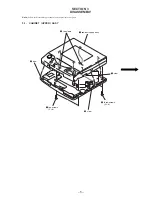
SECTION 5
ELECTRICAL ADJUSTMENTS
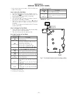
Precautions for Adjustment
1. Before beginning adjustment, set the equipment to service
mode.
After the completion of adjustment, be sure to reset the ser-
vice mode.
For more information, see “Service Mode (Test Mode)” on
page 7.
2. Perform adjustments in the order given.
3. Use YEDS-18 disc (Part No.: 3-702-101-01) unless otherwise
indicated.
4. Power supply voltage requirement: DC6 V
HOLD switch
: OFF
VOLUME control : Minimum
RESUME switch : OFF
Before Beginning Adjustment
Set the equipment to service mode (See page 7) and check the
following. If there is an error, repair the equipment.
• Checking of the sled motor
1. Open the upper lid.
2. Press the
^
key once.
3. Press the
+
and
=
keys and check that the optical pick-
up can move smoothly without sluggishness or abnormal noise
in innermost periphery
→
outermost periphery
→
innermost
periphery.
+
: The optical pick-up moves outwardly.
=
: The optical pick-up moves inwardly.
• Checking of focus searching
1. Open the upper lid.
2. Press the
^
key thrice. (Focus searching operation is acti-
vated continuously.)
3. Check the object lens of the optical pick-up for smooth up/
down motion without sluggishness or abnormal noise.
4. Press the
p
key.
Check that focus searching operation is deactivated. If not,
again press the
p
key slightly longer.
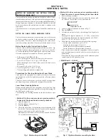
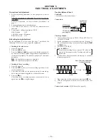
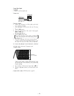
Tracking Balance Check
Condition:
• Hold the set in horizontal state.
Connection:
Checking Method:
1. Connect the oscilloscope to TP524 (TE) and TP534 (VC)
on the MAIN board.
2. Set the equipment to service mode stop state. (See page 7)
3. Move the optical pick-up to the center by pressing the
+
and
=
keys.
4. Put the disc (YEDS-18).
5. Press the
^
key.
From focus searching, focus is turned ON while en-
tering CLV drawing-in mode. Tracking and sled are
turned OFF.
6. Confirm that a waveform on the oscilloscope is vertically
symmetric against 0 V.
7. Stop removing of the disc motor by pressing the
p
key.
8. After the completion of check, reset service mode. (See
page 7)
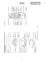
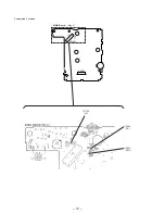
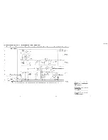
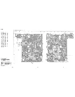
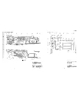
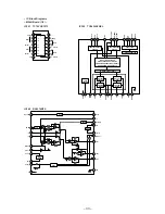
Connection Location: MAIN board (See page 10)
MAIN board
TP524 (TE)
TP534 (VC)
(see page 10)
+
–
oscilloscope
(DC range)
2200 pF
10 k
Ω
A
B
0 V
A
B
0 V
0.7 – 1.1 Vp-p
A=B
A=B
Note: Take long sweep time
for easy monitoring.
Summary of Contents for D-V7000
Page 4: ... 4 SECTION 2 GENERAL This section is extracted from instruction manual ...
Page 10: ... 10 Connection Location CN501 CN701 MAIN Board Side A TP535 RFO TP534 VC TP524 TE ...
Page 12: ......
Page 13: ......
Page 14: ......
Page 15: ......


