


– 42 –
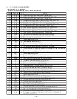
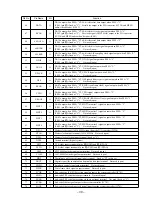
Pin No.
Pin Name
I/O
Function
76
ESP-DATA
O
Serial data output terminal Not used (open)
77
ESP-LT
O
Serial data latch pulse signal output terminal Not used (open)
78
ESP-SENSE
I
Sense serial data input terminal Not used (open)
79
XLASERCTL
O
Laser diode on/off control signal output to the CXA1791N (IC501) “L”: laser on
80
DSP-SCOR
I
Sub-code sync (S0+S1) detection signal input from the CXD2545Q (IC601)
81
OSC1
O
Main system clock output terminal (4.19 MHz)
82
OSC0
I
Main system clock input terminal (4.19 MHz)
83
GND
—
Ground terminal (digital system)
84
XT
I
Sub system clock input terminal Not used (fixed at “L”)
85
XTO
O
Sub system clock output terminal Not used (open)
86
A-SELECT
O
Selection signal output to the DATA, BCLK, LRCK signal select switch (IC301)
“L”: CD play, “H”: video CD play
87
XIRCTL
O
Power supply on/off control signal for the remote control receiver (IC401) “L”: power on
88
SYS XMT RQ
O
Communication request signal output to the MPEG audio/video decoder (IC901)
89
SYS RCV RDY
O
Ready signal output to the MPEG audio/video decoder (IC901)
90
MPG XMT RQ
I
Communication request signal input from the MPEG audio/video decoder (IC901)
91
ESS-DATAO
O
Serial data output to the MPEG audio/video decoder (IC901)
92
ESS-DATAI
I
Serial data input from the MPEG audio/video decoder (IC901)
93
ESS-CLK
O
Serial data transfer clock signal output to the MPEG audio/video decoder (IC901)
94
RESET
I
System reset signal input from the reset signal generator (IC702) “L”: reset
For several hundreds msec. after the power supply rises, “L” is input, then it changes to “H”
95
TEST
I
Service mode setting terminal The stop status is reset with the falling edge of input signal
“L”: service mode, Normally: “H”
96
DBB CTL2
O
MEGA BASS level control signal output terminal
“L”: MEGA BASS level-1, “H”: MEGA BASS level-2 Not used (open)
97
VDDL
—
Power supply output for the liquid crystal display bias
98 to 100 VDD1 to VDD3
—
Power supply output for the liquid crystal display bias
Summary of Contents for D-V7000
Page 4: ... 4 SECTION 2 GENERAL This section is extracted from instruction manual ...
Page 10: ... 10 Connection Location CN501 CN701 MAIN Board Side A TP535 RFO TP534 VC TP524 TE ...
Page 12: ......
Page 13: ......
Page 14: ......
Page 15: ......


