


– 45 –
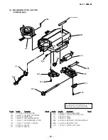
•
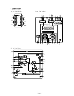
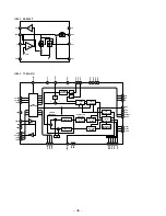
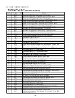
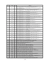
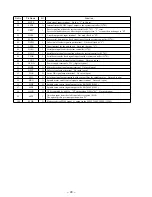
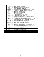
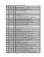
MAIN BOARD IC920 TC90A07U (VIDEO ENCODER)
Pin No.
Pin Name
I/O
Function
1
MIFH
I
Horizontal synchronous signal input from the MPEG audio/video decoder (IC901)
2
MIFFL
I
Vertical synchronous signal input from the MPEG audio/video decoder (IC901)
3
MIFFR
O
Frame synchronous signal output terminal Not used (open)
4
VBLNKI
I
Video blanking signal input terminal “L”: blanking
5
VDD
—
Power supply terminal (+3.3V) (digital system)
6
GND
—
Ground terminal (digital system)
7
YCDI0
I
8 bit pixel data (LSB) input from the MPEG audio/video decoder (IC901)
8 to 13
YCDI1 to
YCDI6
I
8 bit pixel data input from the MPEG audio/video decoder (IC901)
14
YCDI7
I
8 bit pixel data (MSB) input from the MPEG audio/video decoder (IC901)
15
MODE
I
NTSC/PAL mode selection signal input from the MPEG audio/video decoder (IC901)
“L”: NTSC, “H”: PAL
16
VBLNKO
O
Video blanking signal output terminal
17
VDD
—
Power supply terminal (+3.3V) (digital system)
18
GND
—
Ground terminal (digital system)
19
CLPF
I
Low-pass filter on/off control signal input for the internal CbCr “L”: on, “H”: off
Fixed at “L” in this set
20
BF
O
Burst flag pulse output terminal Not used (open)
21
BLK
O
Blanking signal output terminal Not used (open)
22
FLD
O
Field discrimination signal output terminal “L”: odd number field, “H”: even number field
Not used (open)
23
BIAS2
—
Connect a capacitor for the D/A converter bias
24
BIAS1
—
Connect a capacitor for the D/A converter bias
25
VREF
I
Reference voltage input terminal (for D/A converter)
26
AGND
—
Ground terminal (analog system for D/A converter)
27
YOUT
O
Analog Y signal (luminance signal) output terminal Not used (open)
28
AVCC
—
Power supply terminal (+3.3V) (analog system for D/A converter)
29
COUT
O
Analog C signal (chroma signal) output terminal Not used (open)
30
AGND
—
Ground terminal (analog system for D/A converter)
31
CVOUT
O
Analog composite video signal output terminal
32
AVCC
—
Power supply terminal (+3.3V) (analog system for D/A converter)
33
CSYNC
O
Composite synchronous signal output terminal Not used (open)
34
HSYNC
O
Horizontal synchronous signal output terminal Not used (open)
35
VSYNC
O
Vertical synchronous signal output terminal Not used (open)
36
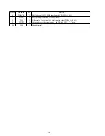
TMS3
I
Mode setting terminal Normally fixed at “H”
37
VDD
—
Power supply terminal (+3.3V) (digital system)
38
CK27I
I
System clock input terminal (27 MHz)
39
XO
O
System clock output terminal (27 MHz)
40
GND
—
Ground terminal (digital system)
41
TMS2
I
Mode setting terminal Normally fixed at “H”
42
CK27O
O
System clock signal (27 MHz) output to the MPEG audio/video decoder (IC901)
43
TMS1
I
Reset signal input from the system controller (IC701) “L”: reset
44
TMS0
I
Video output mode setting terminal “L”: normal output mode, “H”: color bar output mode
Summary of Contents for D-V7000
Page 4: ... 4 SECTION 2 GENERAL This section is extracted from instruction manual ...
Page 10: ... 10 Connection Location CN501 CN701 MAIN Board Side A TP535 RFO TP534 VC TP524 TE ...
Page 12: ......
Page 13: ......
Page 14: ......
Page 15: ......


