


– 46 –
(1)
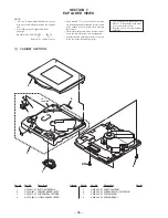
CABINET SECTION-1
SECTION 7
EXPLODED VIEWS
The components identified by
mark
!
or dotted line with mark
!
are critical for safety.
Replace only with part number
specified.
• Items marked “*” are not stocked since they
are seldom required for routine service. Some
delay should be anticipated when ordering
these items.
• The mechanical parts with no reference num-
ber in the exploded views are not supplied.
• Accessories and packing materials are given
in the last of the electrical parts list.
NOTE:
• -XX and -X mean standardized parts, so they
may have some difference from the original
one.
• Color Indication of Appearance Parts
Example:
KNOB, BALANCE (WHITE) . . . (RED)
↑
↑
Parts Color Cabinet's Color
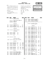
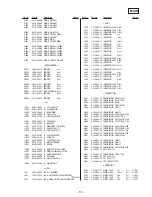
Ref. No.
Part No.
Description
Remark
Ref. No.
Part No.
Description
Remark
4
5
3
2
1
6
6
not
supplied
7
8
1
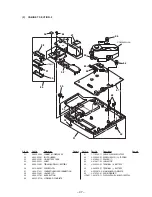
4-996-341-01 BUTTON (CONTROL)
2
X-4950-497-1 CABINET (UPPER) ASSY
3
4-982-475-01 WINDOW, RAY CATCHER
4
A-3320-682-A LID BLOCK ASSY, UPPER
5
4-996-352-01 SHAFT (FULCRUM)
6
3-336-395-01 SCREW (B2X10) (G), TAPPING
7
4-996-347-01 SPRING (LOCK)
*
8
4-996-344-02 SPRING (OPEN)
Summary of Contents for D-V7000
Page 4: ... 4 SECTION 2 GENERAL This section is extracted from instruction manual ...
Page 10: ... 10 Connection Location CN501 CN701 MAIN Board Side A TP535 RFO TP534 VC TP524 TE ...
Page 12: ......
Page 13: ......
Page 14: ......
Page 15: ......


