Chapter 4:
Replacement Procedures
29
Main PCBA Replacement
3
Remove the flex cable from the TGC PCB by lifting on the flex release tab. See
4
Remove the flex cable from the Main PCBA by lifting gently on the flex release tab.
5
Remove the two screws holding the TGC PCBA in place.
6
Reverse steps 1-5 to reinstall the TGC PCB.
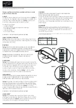
Figure 4.19 TGC PCBA Removal
Release tabs
Screws (2)
Main PCBA
Removal
1
Remove the Power Supply PCBA, SD Card Daughter-card, and TGC PCBA as described in the
previous steps.
2
Remove the 3 screws holding the Main PCBA in place per
. Dissconnect the
speaker wires from the Main PCBA.
Figure 4.20 Main PCBA Screws
Screws (3)
Summary of Contents for M-Turbo
Page 1: ...M Turbo Ultrasound System Service Manual TM...
Page 6: ...2 Chapter 1 Introduction...
Page 20: ...16 Chapter 3 Troubleshooting...
Page 36: ...32 Chapter 4 Replacement Procedures...
Page 44: ...40 Chapter 5 Performance Testing...
Page 52: ...48 Appendix B Service Event Report Service Event Report Form...
Page 56: ...52 Index...
Page 57: ......
Page 58: ...P08144 01 P08144 01...


