background image

Figure 22

Quick Start Guide for HARMONi G3

5.

With the tall side closest to you, install the top shield onto the processor card
shield 

(Figure 21); 

verify that it is snapped securely into place.

Install FireWire Adapter Card

1.

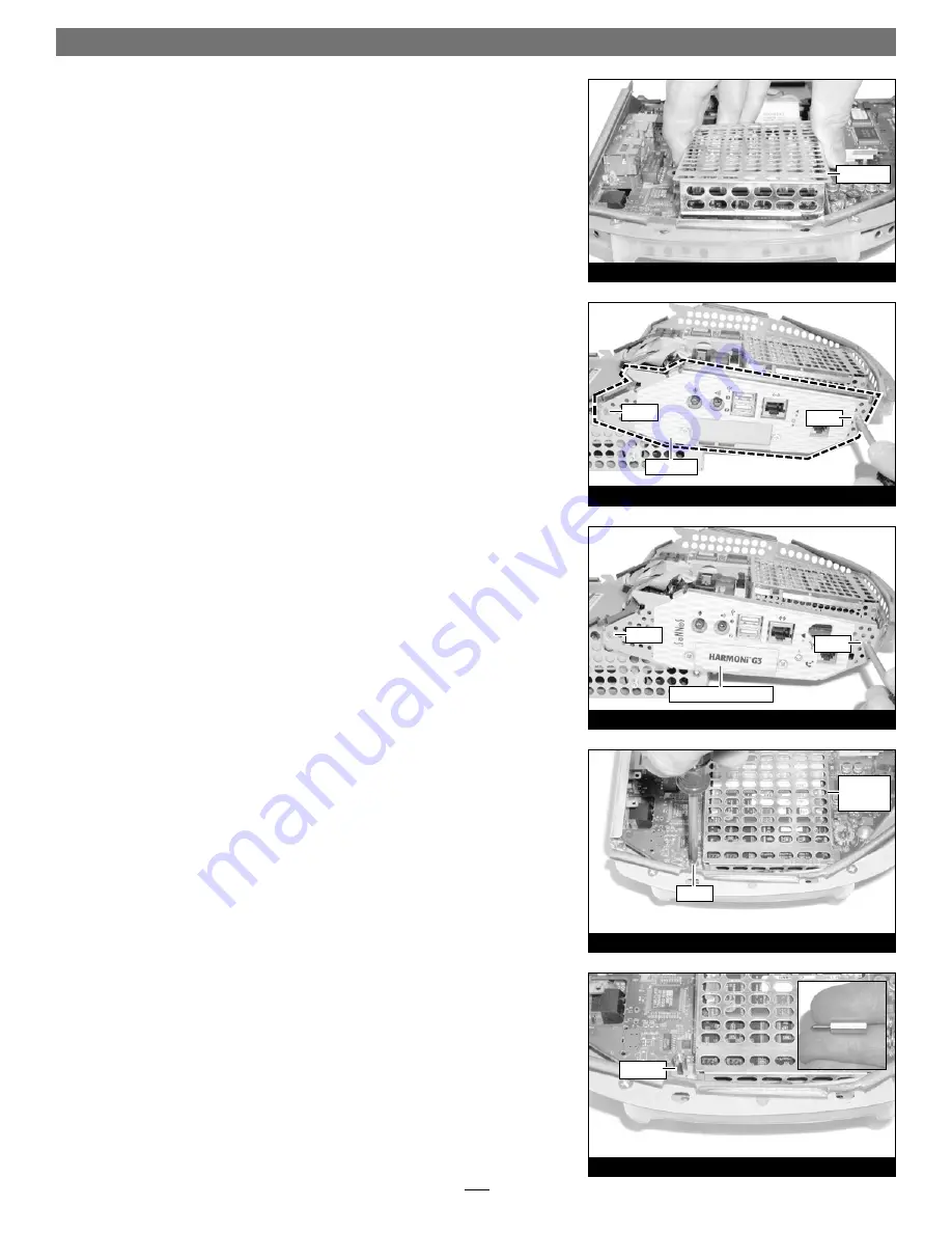
Locate and remove the two screws (#1 Phillips) securing the plate on the side
of the logic board/drive assembly, then remove the plate 

(Figure 22)

. Please

note that the side plate on your iMac may appear different than the one pic-
tured.

2.

Install the replacement side plate, securing it with the original flat head
screws 

(Figure 23)

do not overtighten the screws

. Note that the side plate holes

should line up with the connectors on the logic board/drive assembly. 

3.

Locate and remove the screw (#1 Phillips) securing the lower processor card
shield to the logic board 

(Figure 24)

.

4.

Screw in, finger tight, the supplied support standoff in place of the screw you
just removed 

(Figure 25)

7

Figure 25

Figure 24

Figure 23

Figure 21

top shield

screw

screw

screw

screw

standoff

side plate

screw

replacement side plate

processor

card

shield

Summary of Contents for HARMONi G3

Page 1: ...Phillips screwdrivers Flat blade screwdriver Soft clean towel System Requirements The HARMONi requires the following in order to work in your system Fully operational original processor you must install Sonnet software prior to installing the HARMONi parts FireWire 2 3 3 or later this driver should be installed after HARMONi has been installed instructions follow Software updates and links are ava...

Page 2: ...e click the Shut Down button to shut down your computer Quick Start Guide for HARMONi G3 Support Note Before proceeding with any other part of this installa tion you must ensure that your system has the latest firmware installed If you have already installed Mac OS 9 or later you may skip this section and go to the next section Install Sonnet Software Support Note Before proceeding with the HARMON...

Page 3: ...move the screw if present securing the clamp on the left side Figure 4 Using a flat blade screwdriver unscrew the thumb screws securing the large connector to the assembly then disconnect the cable 3 Disconnect the remaining connectors from the logic board drive assembly Figure 5 Remove Connector 1 by pressing in its locking tab and pulling the connector straight out Remove Connector 2 by pulling ...

Page 4: ...cing you Figure 8 Remove Processor Card 1 Unhook a long edge of the metal shield covering the processor card then remove it from the logic board drive assembly Figure 9 2 While grasping the underside the logic board drive assembly and the top of the heat sink clip with one hand use a flat blade screwdriver to carefully unhook the heatsink clip from the processor card shield Figure 10 Remove the cl...

Page 5: ...rd aside on a static free surface 2 Remove the HARMONi processor card from its anti static bag making sure to handle the card by its edges Figure 14 If present on the card remove the foam block protecting the small 4 pin connectors 3 Turn the HARMONi processor card over so that the two long connectors are face up Figure 15 Align the RAM module removed from the bottom of the original processor card...

Page 6: ...e the card around until the connectors on the bottom of the card engage with the corresponding con nectors on the logic board Figure 17 2 Firmly press on the bottom right portion of the HARMONi processor card until the connectors are completely coupled Figure 18 3 With the two small sections of fins on the left place and center the heatsink on top of the HARMONi processor card above the DIMM slot ...

Page 7: ... different than the one pic tured 2 Install the replacement side plate securing it with the original flat head screws Figure 23 do not overtighten the screws Note that the side plate holes should line up with the connectors on the logic board drive assembly 3 Locate and remove the screw 1 Phillips securing the lower processor card shield to the logic board Figure 24 4 Screw in finger tight the sup...

Page 8: ...age making sure to handle the card by its edges Figure 28 9 Plug in the 2 pin connector at the end of the yellow wire to the adapter card s 2 pin connector Figure 29 Verify the connector is plugged in securely 10 Using the screw holes to align it set the adapter card on top of the side plate s brackets and the support standoff Figure 30 the small connectors on the bottom of the adapter card should...

Page 9: ...ly with the other then slowly lower the assembly into the computer Figure 34 If there is any resistance pull the assembly back out make sure all cables and connectors are routed prop erly then lower the assembly into the computer again 2 Carefully tilt the computer to check and verify that the CD ROM drawer is aligned properly in the opening in the front of the iMac Secure the logic board drive as...

Page 10: ...ight tones 3 Your iMac will restart Your accelerated machine should boot normally If Mac OS 9 2 or later is already installed in your system your iMac is ready to use and your installation is complete Otherwise continue reading Installing Mac OS 9 any version Only if you are upgrading to Mac OS 9 as part of this installation do so now oth erwise skip to the next section appropriate to your version...

Page 11: ... 9 1 CD Complete these steps only if you installed Mac OS 9 1 before installing the HARMONi upgrade If you installed Mac OS 9 1 after installing the HARMONi upgrade your installation is complete 1 Start up your computer from the Mac OS 9 1 CD and double click the Mac OS Install application In the Select Destination window click the Select button Proceed through the next several screens until you r...

Reviews: