4
4.
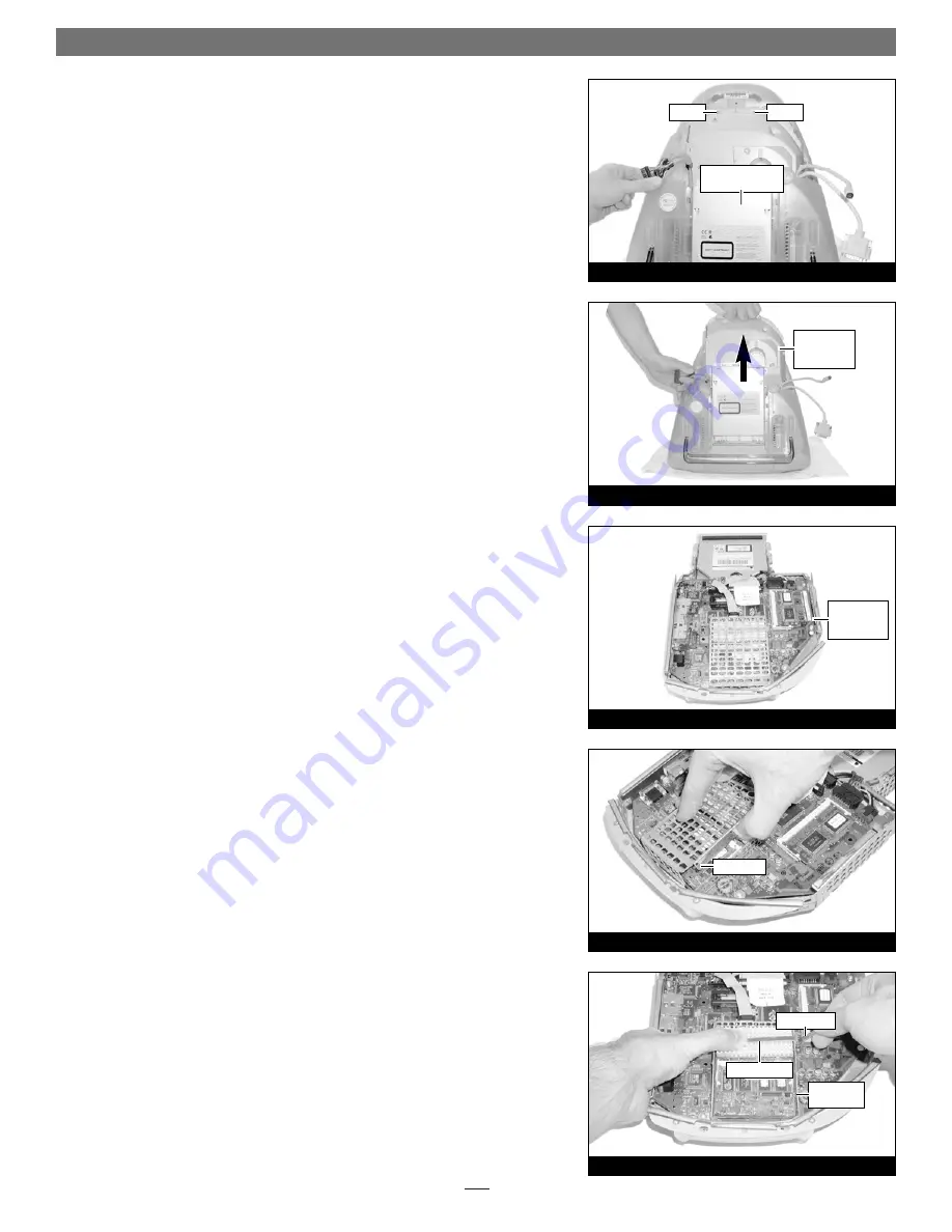
Move the cables off to the sides of the logic board/drive assembly
(Figure 6)
.
5.
Locate the two screws (#2 Phillips
)
inside the plastic handle
(Figure 6)
, then
remove them; set the screws aside.
6.
Using the handle, carefully lift the logic board/drive assembly out of the
computer
(Figure 7)
;
when it becomes possible, use both hands to support the
assembly
.
7.
Set the logic board/drive assembly on a clean, flat surface, with the curved
portion of the assembly facing you
(Figure 8)
.
Remove Processor Card
1.
Unhook a long edge of the metal shield covering the processor card, then
remove it from the logic board/drive assembly
(Figure 9)
.
2.
While grasping the underside the logic board/drive assembly and the top of
the heat sink clip with one hand, use a flat blade screwdriver to carefully
unhook the heatsink clip from the processor card shield
(Figure 10)
. Remove
the clip and set it aside.
Quick Start Guide for HARMONi G3
Figure 10
Figure 9
processor
card shield
top shield
heat sink clip
screwdriver
Figure 7
Figure 8
Figure 6
logic board/drive
assembly
logic
board/drive
assembly
logic
board/drive
assembly
screw
screw


