background image


Stenner Chemical Pump 


Tube Replacement Instructions 


1. 

Remove the three cover screws. Lift the cover free. 


2. 

Set the Feed Rate Dial on #1. Turn the feeder switch 

on. Line up the slot in the roller assembly with the lower 

or "IN" tube fitting. 


3. 

With the feeder dial set on #1, lift the tube housing out 

of the housing slot and pull it toward the center of the 

roller. Start the motor while pulling on the tube until it 

comes completely out of the housing. Turn the feeder off. 


4. 

To install a new tube assembly, position the roller 

assembly until the slot is again in line with the "IN" or 

suction fitting (See drawing for roller position). Place the 

tube fitting into position and push the tube into the slot of 

the roller assembly. With the feed rate dial set on #1, start 

the motor and feed the tube into the slot as the roller 

assembly turns. Be careful of your fingers. Do not force 

the tube. Avoid kinds. When the roller assembly slot lines 

up with the "OUT" tube housing slot, quickly pull the tube 

Summary of Contents for SPC-75S

Page 1: ...Operation Service Manual SPC 75s Close Coupled Pulping System 165 Independence Ct Lancaster Pa 17601 Ph 800 237 6628 Fax 717 291 0878 ...

Page 2: ... Phone Number Rep Dealer Rep Dealer Phone Number Somat Service Dept 800 237 6628 x 176 Somat Parts Dept 800 237 6628 x 133 parts somatcompany com To expedite service or parts please have the above information available before you call The serial number of your machine is located inside of the main electrical control panel for your Somat equipment ...

Page 3: ...r part which shall have been repaired or altered by any person not employed or retained by SOMAT so as in the judgment of SOMAT to affect its operation and reliability nor which has been installed operated or maintained contrary to SOMAT OPERATION or PREVENTIVE MAINTENANCE INSTRUCTION MANUALS or to other written instructions or drawings approved by SOMAT nor which has been subject to misuse neglig...

Page 4: ... Description Definitions Installation Unpacking Mechanical Installation Plumbing Installation Electrical Installation Start up Forms Lists Warranty Validation Operation Cleaning Maintenance Cleaning Maintenance Troubleshooting Replacement Parts Pulper Extractor Electrical Panel ...

Page 5: ...E ADJUSTMENTS OR CLEANING OF THE UNIT BEFORE STARTING BE SURE ALL PERSONNEL ARE CLEAR OF MOVING PARTS KNOW LOCATION AND FUNCTIONS OF ALL START STOP BUTTONS AND SAFETY SWITCHES DURING PERIODIC MAINTENANCE CHECK ALL SAFETY SWITCHES TO BE SURE THEY ARE OPERATING PROPERLY DO NOT REMOVE OR ALTER GUARDS DO NOT REMOVE SAFETY LABELS IF LABELS ARE MISSING OR DESTROYED CONTACT FACTORY FOR REPLACEMENT DO NOT...

Page 6: ...or serious injury can occur if warnings are not followed This equipment has moveable lids protecting you from moving parts Do not alter safety devices or guards Do not reach into any part of the unit with the power turned on This equipment uses High Voltage Only trained and authorized personnel should perform maintenance on the electrical components of this machine This equipment has moving parts ...

Page 7: ...chine s Keep these items out of the machine s to avoid component failure and unwanted downtime When in doubt keep it out of the machine s Glass Bottles Jars Cans Silverware Metal of any kind China Pans Wood Towels Rags Scrub Pads Always turn the power off before servicing the pulper ...

Page 8: ...own flow of water and the rotation of the Pulper impeller create a strong vortex action which pulls the waste down against the cutting blades of the impeller The resultant slurry is then forced through a perforated stainless steel Sizing Ring surrounding the impeller Items such as tin cans silverware nails bolts and other non palpable objects which may be inadvertently fed into the Pulper are sepa...

Page 9: ... plug This plug is broken up at the Hydra Extractor discharge opening by a cutter and the pulp then falls out of the discharge chute TYPICAL HYDRA EXTRACTOR This system is capable of reducing the volume of average non compacted waste by approximately 80 percent The system is powered by electric motors with the associated controls housed in Som A Trols electric control panels Since in the course of...

Page 10: ... that adds de foaming deodorizer and or buffering solutions to the process water 10 Pulp Screw Conveyor Transport screw used for conveying pulp to a point remote from Hydra Extractor 11 Distributing Type Pulp Screw Conveyor Transport screw with discharge ports throughout its length for even distribution in large haul away containers 12 Water economizing tank Reservoir for return water used in larg...

Page 11: ...hed to edge of screw helix which serves to clean the screen 5 Plug Cutter Assists in breaking apart waste to discharge down the chute GENERAL 1 Throttling Valve Full ported gate valve used to control water flow 2 Timer Electrical device used to automatically shut down the SOMAT System at a pre determined time 3 Fresh Water Solenoid Electric valve used to control fresh water make up to the SOMAT Sy...

Page 12: ...Installation ...

Page 13: ...s Installation Drawings UDT UNITS ONLY Stainless Steel Lid Stainless Steel Cone Adapter Unless shipped directly to table manufacturer UDT Gasket TRAY ONLY Gasket Hardware Return Water Assembly TROUGH ONLY Trough Gasket Hardware Trough Nozzles Throttling Gate Valves See Installation Drawing for quantity OPTIONAL EQUIPMENT Remote Push Button Station Trough Magnet Hardware Feed hood ...

Page 14: ... the table as shown in the Installation Drawing using the following diameter SPC 75S Pulper 22 Diameter hole 2 Center the provided UDT Cone beneath the opening and weld it into place as shown Please follow print detail for welding instructions 3 Put the Pulper into position 4 Place the anti vibration pads under each leg of the Pulper and Hydra Extractor 5 Install the UDT gasket onto the Pulper tan...

Page 15: ...erred Locate per detail below and weld into place Optional Drill four 7 32 diameter holes into the trough as shown below Seal the heads of the provided screws with silicone and attach the magnet RECOMMENDED POSITION OF THE GRABBER MAGNETS ...

Page 16: ...MOUNTING DETAIL OF TROUGH ...

Page 17: ...D PIPING FROM FREEZING AND CONDENSATION 7 ALL PIPING TO BE IN ACCORDANCE WITH STATE AND LOCAL PLUMBING CODES 8 F FURNISHED BY SOMAT NF NOT FURNISHED BY SOMAT FRESH WATER NOTE In Massachusetts the Public Water Supplier shall be contacted regarding the proper backflow prevention device to be installed 1 Bring a 1 2 cold water line for theSPC 75S to the pre piped fresh water assembly See enclosed dia...

Page 18: ...ngs 2 Install one side of the provided tubing over the return water elbow on the feed tray and the other side onto the pump return water assembly if not already factory installed 3 Install the provided hose clamps at each connection RETURN PIPING FOR UNITS WITH A TROUGH 1 Pipe from the return pump to the supplied trough end flush nozzle and silver saver connections as well as to the optional troug...

Page 19: ...DE NEC 1993 SPECIFICATIONS 5 INTEGRAL PUSH BUTTONS ARE LOCATED IN PANEL DOOR AND PRE WIRED AT FACTORY OPTIONAL REMOTE PUSH BUTTON STATION IF SUPPLIED TO BE MOUNTED WIRED AT WORK STATION BY ELECTRICIAN BRACKET REQUIRED BY CUSTOMER PANEL OPTIONAL REMOTE PBS MOUNTING 1 Mount the Som A Trol in a suitable location see Installation Drawings so that the bottom of the panel is at least 42 above the finish...

Page 20: ...l the motor wires and control wires thru these conduits separately and do your final wire terminations matching numbers from panel to pre wire junction box REMOTE PUSH BUTTON STATION Mount the remote push button station run the conduit from the remote push button station to the prewired junction box then pull the wires from the remote push button station to the prewired junction box and do your fi...

Page 21: ...FOR REFERENCE ONLY ...

Page 22: ...Start Up ...

Page 23: ...t equipment carries a 1 year warranty from date of start up To accurately track this information we ask that you fill out the Warranty Registration Sheet below and fax back to us This will ensure your equipment is registered with Somat s Service Department and will allow Somat s Service Department to efficiently process a warranty claim if one should arise You will also find copies of instructions...

Page 24: ...____________ State ____________ Zip ______________ Contact Name _____________________________________________________________ Contact Number ________________________ Fax ______________________________ Service Company __________________________________________________________ City ______________________________ State _____________ Zip _____________ Please fax to Somat Company Service Department 717...

Page 25: ...ELEASE STOP BUTTON o PULL OUT ON EMERGENCY STOP o ENSURE POWER IS ON PRESS GREEN START BUTTON TO OPERATE MACHINE TO STOP AND SHUTDOWN PULPER TO STOP PULPER PRESS RED STOP BUTTON ONCE AT END OF DAY PRESS BLACK TIMED STOP PUSHBUTTON ONCE WAIT UNTIL UNIT SHUTS DOWN BY ITSELF PRESS DRAIN PUSHBUTTON ON MAIN PANEL DOOR LOCK IN STOP BUTTON WITH LOCKING LEVER CLEAN UNIT TO START UNIT AFTER TIMED STOP PRES...

Page 26: ...Operation ...

Page 27: ...ore feeding waste to the Pulper either manually or by starting waste down the flushed trough if so equipped Waste Feeding Instructions Best results are obtained if the Pulper is fed waste at a UNIFORM RATE Under normal conditions waste may be fed to the Pulper as long as a strong vortex is maintained in the tank If waste is fed too fast the vortex will diminish to a point where it will no longer p...

Page 28: ...Lock in the STOP button lock and turn power off to perform any cleaning or maintenance 5 Refer to the applicable Pulper and Hydra Extractor maintenance sections of this manual for daily weekly and long term shutdown cleaning procedures and maintenance instructions To ensure all food waste is removed from the extractor you can use Styrofoam plates as a cleaning agent for the unit The Styrofoam will...

Page 29: ...ELEASE STOP BUTTON o PULL OUT ON EMERGENCY STOP o ENSURE POWER IS ON PRESS GREEN START BUTTON TO OPERATE MACHINE TO STOP AND SHUTDOWN PULPER TO STOP PULPER PRESS RED STOP BUTTON ONCE AT END OF DAY PRESS BLACK TIMED STOP PUSHBUTTON ONCE WAIT UNTIL UNIT SHUTS DOWN BY ITSELF PRESS DRAIN PUSHBUTTON ON MAIN PANEL DOOR LOCK IN STOP BUTTON WITH LOCKING LEVER CLEAN UNIT TO START UNIT AFTER TIMED STOP PRES...

Page 30: ...achines Solid Green All safeties are latched and secure system is ready to run Flashing Green System is in timed stop mode extractor will spray after less than 10 minutes system will shut down Slow flashing Green Unit drain is open press Green pushbutton to close drain Two Green flash pause and repeat All safeties are latched and secure tank is filling Solid Red One of systems 3 motors is overload...

Page 31: ... SOMAT Pulper is designed to handle a limited amount of non pulpable material The lighter items are eventually ground and the heavier material is discharged into the junk box However the SOMAT Pulper is not designed to handle heavy masonry materials or tramp iron and other materials of this nature Such items will break away the cutting teeth and seriously reduce the machine s ability to handle mat...

Page 32: ...CLEANING YOUR SYSTEM ...

Page 33: ...ER 2 Wash the interior of the Pulper shell with a hose suitable brush detergent and deodorant or other cleaning solution Exercise particular care in cleaning the underside of the upper shell flange 3 Wipe down the equipment exterior 4 Leave lid open if allowed to let machine air out and reduce odors Close lid and follow start procedure to refill unit To ensure all food waste is removed from the ex...

Page 34: ...o combat bacteria growth and odor 2 Remove the impeller from the Pulper refer to Pulper Maintenance Section Do not remove the mechanical seal Using a hose and brush thoroughly clean the mechanical seal slurry chamber and the underside of the impeller To ensure all food waste is removed from the extractor you can use Styrofoam plates as a cleaning agent for the unit The Styrofoam will force out the...

Page 35: ...n the SOMAT System to keep it clean to deodorize and to reduce grease build up This is an industrial strength product The surfactants in this detergent deodorant are bio degradable SOMAT DEFOAMER 73000 A neutral liquid silicone emulsion specifically designed for suppressing and controlling undesirable foam This is an industrial strength product The surfactants in this de foamer are bio degradable ...

Page 36: ...d corrosion is caused by low pH level in the system water but it can be easily controlled by the addition of commercial grade soda ash Soda ash is readily available and costs only a few cents a pound in bulk lots Alkaline Corrosion is caused by high pH level in the system water While damages done by this condition does not occur as quickly as that of Acid corrosion neutralizing agents should be ad...

Page 37: ...e whether the liquid is acid or alkaline 2 Neutral water is neither acidic nor alkaline and will have a pH of 7 0 An acid liquid will have a pH of less than 7 0 as is indicated by the color change of the litmus paper 3 If the liquid is neutral a pH of 7 0 no treatment is required NOTE SOMAT Company cannot be responsible for failure due to corrosion resulting from improper water conditions ...

Page 38: ...MAINTENANCE ...

Page 39: ...ng teeth as these will sustain the highest degree of wear Continued adherence to these inspections will provide adequate lead time when ordering spare parts thereby minimizing unnecessary and costly equipment downtime PREVENTIVE MAINTENANCE INSPECTION SCHEDULE PULPER DAILY WEEKLY MONTHLY QUARTERLY 1 GENERAL a Check shell and slurry chamber for wear X b Check exterior finish for corrosion X 2 IMPEL...

Page 40: ...R DAILY WEEKLY MONTHLY QUARTERLY 1 GENERAL Overhaul Yearly a Check exterior finish for corrosion X 2 EXTRACTING UNIT a Check screw and brush for wear X b Check screen for wear X 3 DRIVE a Check reducer for noise and leakage X b Check bushing and screw shaft for wear X Lubrication Chart FREQUENCY TYPE OF FITTING LUBRICANT Hydra Extractor speed reducer 6 months to 1 year Oil fill plug Amer Worm Gear...

Page 41: ...DAILY WEEKLY MONTHLY QUARTERLY 1 GENERAL a Check exterior finish for corrosion X b Check pump casing for wear X c Check impeller for wear X 2 DRIVE a Check seals for leakage X b Check bearings for noise and wear X ...

Page 42: ... Remove conduit from motor junction box Remove the drive motor 4 from the slurry chamber assembly by removing four machine screws 5 6 MECHANICAL SEAL REMOVAL Remove spring and upper seal ring prior to removing motor With motor removed push upward on Ni Resist Seal until it can be removed MECHANICAL SEAL INSTALLATION Clean the seal cavity and moisten the o ring of the Ni Resist Seal with soapy wate...

Page 43: ...EAR REPLACEMENT Remove two screws 7 that hold impeller cutter ear 6 to impeller 1 NOTE Screws may be loosened by gently heating with a propane torch IMPELLER CUTTER EAR RE SHARPENING Rotating blades may be re sharpened as cutting efficiency decreases Remove impeller as described above Remove attaching hardware for cutting ears Using a gloved hand firmly grasp blade and with an angle grinder grind ...

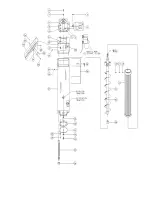
Page 44: ...TOR SCREEN AND SCREW REMOVAL After removing four machine screws 12 13 14 from head assembly 11 lift head with screen 15 and screw assembly 19 attached from the Hydra Extractor shell 27 By removing a machine screw 23 24 25 the plug cutter 22 can be removed from the screw assembly Remove the screw assembly from the screen assembly by pulling the screw assembly through the bottom opening of the scree...

Page 45: ...disc into adapter seat bore with polished side up Take extreme caution to not damage polished side as this will cause immediate leaks Ensure seal is seated to bottom of adapter seat bore If needed use a wooden dowel and gently tap into place to ensure tight seat into bore 8 Replace impeller assembly back onto motor shaft Use a light coating of anti seize on motor shaft to ensure smooth seating 9 P...

Page 46: ...e to motor shaft 5 Remove impeller with drive sleeve as an assembly taking care not to damage mechanical seal or pumping vanes 6 Remove 4 3 8 16 x hex head screws from adapter plate to motor 7 Remove adapter unit from motor 8 Replace motor as required properly wiring unit Ensure that wiring is for correct voltage 9 Replace pump pak as described in MECHANICAL SEAL REMOVAL SECTION s 8 14 ...

Page 47: ...on the tube until it comes completely out of the housing Turn the feeder off 4 To install a new tube assembly position the roller assembly until the slot is again in line with the IN or suction fitting See drawing for roller position Place the tube fitting into position and push the tube into the slot of the roller assembly With the feed rate dial set on 1 start the motor and feed the tube into th...

Page 48: ...er screws left loose Major Components Disassembly Assembly Instructions No tools are necessary TO DISASSEMBLE 1 Unplug feeder power cord and remove chemical lines 2 Grasp the mechanical feed rate control section and turn it clockwise until it stops Pull straight off shaft 3 The tube housing complete can be removed from the feed rate control in the same manner TO ASSEMBLE 1 Align the mechanical fee...

Page 49: ...TROUBLESHOOTING ...

Page 50: ...ned out replace with a new valve SYMPTOM POSSIBLE CAUSE CORRECTIVE ACTION Too much water in Pulper 1 Trough valve open too far 2 Misadjusted PLC POT setting 3 Faulty operation at valve see equipment schematic for location 4 Overflow fitting and line clogged 1 Throttle down valve to decrease water in pulper and increase water in extractor more overflow 2 The PLC controls the circuit to the solenoid...

Page 51: ...e Refer to Pulper maintenance section Check water level control it may be adjusted too low See previous section 2 Refer to Pulper maintenance section for replacement procedure 3 Adjust or replace blades in accordance with Pulper maintenance section of manual 4 Add a de foamer or any other suitable commercial preparation See Section 5 5 See below a See Previous section b Revise waste feeding rate s...

Page 52: ...e Refer to Pulper maintenance section Check water level control it may be adjusted too low See previous section 2 Refer to Pulper maintenance section for replacement procedure 3 Adjust or replace blades in accordance with Pulper maintenance section of manual 4 Add a de foamer or any other suitable commercial preparation See Section 5 5 See below a See Previous section b Revise waste feeding rate s...

Page 53: ... of screen 2 Worn screw and brush 1 Clean the Hydra Extractor screen Refer to Hydra Extractor Maintenance Section of the manual 2 Send worn screw back to SOMAT Company for repair Remove screw and replace Refer to Hydra Extractor Maintenance Section of this manual SYMPTOM POSSIBLE CAUSE CORRECTIVE ACTION Hydra Extractor stops frequently 1 Worn Screw 1 Replace screw Heavy flow from overflow pipe 1 E...

Page 54: ... impeller assembly is excessive Replacement of the impeller assembly and or the security ring is required Slight clicking sound when machine is operating Impeller cutter ear may be loose Tighten the hex head bolts that hold the impeller cutter ear Use Loctite red SYMPTOM POSSIBLE CAUSE CORRECTIVE ACTION Decreased pulping rate or excessive unpulped material left in Pulper tank after shut down Dull ...

Page 55: ...mpeller worn or clogged 2 Clogged lines 1 Check impeller clean or replace as required 2 Check individual cleanouts for loss of pressure to locate blockage Remove blockage Seal Leaking 1 Worn or damaged seal or motor 1 Check seal and motor shaft Replace as required ...

Page 56: ...REPLACEMENT PARTS EXPLODED VIEWS ...

Page 57: ......

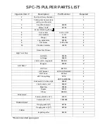
Page 58: ...ation Isolator 16200 4 Items Not Shown High Tank Only Lid latch 35100 1 Lid hinge 35613 2 Limit switch magnetic 54999 1 1 Magnet 55005 1 UDT ONLY UDT Lid 84772 1 1 UDT Gasket SP75 UDTGASKET 1 UDT Cone 57316 1 1 UDT Clamp Ring SP75 UDTCLAMPRING 4 Limit switch in tube style 59942 1 Limit switch cord 59943 1 Pipe Cap 20469 1 Nipple 43041 1 Elbow 26850 1 1 TRAY ONLY Curtain 23 3 4 x 13 23070 1 Curtain...

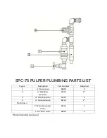
Page 59: ...IST Figure Description Part Number Required 1 Gate valve 64803 2 2 Backflow preventer 11310 2 3 Shock arrestor 11303 2 4 Solenoid valve 64710 2 Not Shown 2 Motor Operated Valve 64742 1 1 1 2 Gate valve 64825 2 Recommended spare part ...

Page 60: ......

Page 61: ...ot shown Lock washer ID 1 4 not shown 75 Impeller washer 89201 1 5 not shown Key stock 5 16x5 16x1 1 6 Rotating blade 24975 2 Rotating Blade Attaching Hardware 7 Screw hex 3 8 16 x 5 8 6 8 Security ring assembly with blades 87075 1 9 Stationary blades 80988 4 Stationary Blade Attaching Hardware 10 Screw socket head flat 20 x 1 1 4 2 ea blade Recommended spare part ...

Page 62: ......

Page 63: ...10 Nut hex 3 8 16 4 11 Head assembly 89306 1 Head Assembly Attaching Parts 12 Screw hex 5 16 18 x 4 13 Lock washer 5 16 ID 4 14 Nut hex 5 16 18 4 15 Screen assembly 54005 1 Screen Assembly Attaching Parts 16 Screw buttonhead 5 16 18 x 1 2 2 17 Lock washer 5 16 ID 2 18 Nut hex 5 16 18 2 19 Screw assembly 86820 1 20 Brush nylon 16000 4 21 Key stock 3 8 x 3 8 x 3 1 22 25 No part 26 Bushing lower 8135...

Page 64: ...crew hex 13 x 1 1 44 Screw hex 3 8 16 x 1 6 45 Lock washer 3 8 ID 6 46 Nut hex 3 8 16 6 47 Discharge Chute 81531 1 Discharge Chute Attaching Parts 48 Screw round head 10 32x 2 49 Nut hex 10 32 2 50 Limit switch magnetic 54999 1 1 Limit Switch Attaching Parts 51 Magnet high energy 55007 1 52 Screw round head 10 32 x 1 1 4 2 53 No part 54 Nut nyloc 10 32 2 55 not shown Rubber hose to return pump 268...

Page 65: ...Seal 1 MP22272 1 4 O Ring MP34555 1 5 Spacer Ring MP34521 1 6 Screw hex 3 8 16 x 4 7 Lock washer 3 8 ID 4 8 Stud 5 16 18 x 1 4 9 Lock washer 5 16 ID 4 10 Nut hex 5 16 18 4 11 Clamp S S 5 16 2 12 Screw hex 5 16 18 x 1 3 4 2 13 Drive sleeve MP30670 1 Recommended spare part Item comes as one piece assembly not individual parts ...

Page 66: ... dangerous nature of all electrical control equipment Somat Company recommends maintenance and repair of the Som A Trol be performed by qualified personnel only Qualified personnel should find the electrical drawings supplied to be sufficient guidance for troubleshooting ...

Reviews: