


4.6
Equaliser Section
Routing Buttons
There are three buttons associated with this section of the unit. Section 5 describes the routing
combinations in more detail but, briefly, these buttons function as described below.
EQ IN –
Switches the EQ section into circuit.
DYN SC –
Switches the EQ section into the sidechain of the Dynamics section. The Filter section can be
switched independently of the EQ section. If both Filter and EQ sections are assigned to the dynamic
sidechain the Filter section precedes the EQ.
E –
Switches the EQ from ‘G’ operation to ‘E’ operation – see below.
Operation
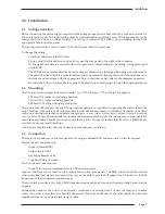
This is a 4-band equaliser that can be switched between two different sets of curves, one based on SSL’s G
Series EQ and the other based on the latest version of the classic E Series EQ.
HF Section: Frequency range 1.5kHz – 22kHz, gain ±20dB.
LF Section: Frequency range 40Hz – 600Hz, gain ±16.5dB.
The HF and LF sections provide shelving equalisers with variable turnover frequency. Normally the curve
has a degree of overshoot/undershoot (depending on whether you are boosting or cutting) below the
selected HF frequency (or above the selected LF frequency). Selecting the ‘E’ button removes the
overshoot/undershoot effect and provides a slightly gentler slope. Selecting BELL in either mode switches
the equaliser to a peaking curve.
HMF Section: Centre frequency 600Hz – 7kHz, gain ±20dB, continuously variable Q (0.7 – 2.5).
LMF Section: Centre frequency 200Hz to 2.5kHz, gain ±20dB, continuously variable Q (0.7 – 2.5).
Normally, at any Q setting, the bandwidth of the HMF and LMF sections varies with gain, whereby an
increase in boost or cut increases the selectivity of the EQ. This type of EQ can sound effective when used
at moderate settings; the gentle Q curve lends itself to the application of overall EQ on combined sources
and subtle corrective adjustments to instruments and vocals.
When the EQ is switched to ‘E’ operation, the bandwidth of the HMF and LMF sections remains constant
at all gains, so at lower gains the EQ curves are comparatively narrower for a given Q setting. This is
particularly useful for drums, since relatively high Q is available at low gain settings. However, it is not
so suitable for overall EQ or subtle corrections, as you need to adjust the Q to maintain the same effect
when the gain is changed.
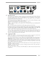
4.7
Output Section
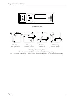
The Output section consists of a ±20dB output gain control, indented at
centre and a 7-segment LED meter. Normally the meter reads the output of
the channel, but selecting
MTR INPUT
will meter the signal immediately
post the input section.
The blue
POWER
LED indicates that the unit is powered (what else?).
The
ADC LOCK
LED indicates that the (optional) ADC card is locked to an
external clock.
Operation
Page 11
KHz
.6
1
5
Q
Q
Hz
40
600
60
400
KHz
.2
2.0
.3
1.6
HF
+
GAIN
LMF
+
GAIN
LF
+
GAIN
HMF
BELL
IN
EQ
E
DYN
S/C
2
150
220
.6
1.0
7
KHz
1.5
22
2
15
+
GAIN
BELL
3
5
10
GAIN
12
6
0
-12
-24
24
18
MTR
INPUT
+20
-20
OUTPUT
ADC LOCK
POWER
Summary of Contents for XLogic Super Analogue
Page 1: ...Super Analogue Channel Owner s Manual ...
Page 2: ......
Page 29: ...Notes Appendix Page 25 ...


