


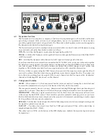


4.0 Operation
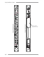
The XLogic Channel unit is a 1U rack mounting unit containing a complete set of signal processing from the
XL 9000 channel strip – Input, Compressor/Limiter, Expander/Gate, Hi and Lo pass filters and Equaliser.
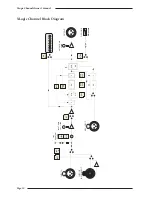
The signal processing order can be changed and the EQ and filter sections used in the dynamics side chain.
providing a wide range of signal processing options.
Obviously there are many different permutations of signal routing, allowing an enormous number of creative
possibilities. This section looks at each control on the XLogic Channel individually, with a brief summary of the
routing possibilities. See Section 5 for more on routing.
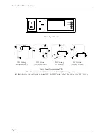
4.1 Channel Input Section
The channel input can pick up any one of three inputs:
INP A
With the
INP B
and
INST
switches released
the input is fed by the INPUT A XLR on the rear of the
unit.
INP B
– Selects the female XLR on the front of the
unit.
INST
– Selects the mono jack instrument input on the
front of the unit. This is a very high impedance
unbalanced input intended to be used with guitar
pickups etc.
The stepped
INPUT GAIN
control has a gain range of +6dB to +72dB in 6dB steps.
HI-Z
– Increases the input impedance of the microphone input (inputs A or B) from 1.2kΩ to 8.45kΩ. This
allows the connection of line level signals to the channel input if required, and provides an alternative
input impedance for some dynamic microphones.
PAD
– This switch reduces the signal level by 18dB. Setting the gain to +18dB and selecting PAD sets the
input gain to 0dB for use with line level signals.
48V
– When selected provides phantom power to the associated microphone.
Please note that connecting a microphone to the XLogic Channel unit with phantom power switched on is not advised
as it may cause damage to either the microphone or the input stage of the XLogic Channel unit. Also note that
phantom power should be switched off before changing the input source to avoid possible damage to connected devices
or to the input stage of the XLogic Channel unit. Take care not to use phantom power when connecting line level
sources (keyboards etc.) as this may damage the output stage of the connected unit.
Ø (Phase)
– This reverses the phase of the selected channel input.
XLogic Channel Owner’s Manual
Page 8
PAD
48V
HI Z
dB
72
INP
B
INST
66
60
54
48
42
36
30
24
18
12
6
INPUT B - INSTRUMENT
INPUT GAIN
Ø
Summary of Contents for XLogic Super Analogue
Page 1: ...Super Analogue Channel Owner s Manual ...
Page 2: ......
Page 29: ...Notes Appendix Page 25 ...


