3.0 Installation
3.1
Voltage Selection
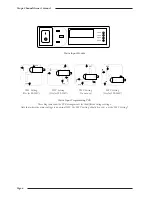
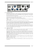
Before connecting the mains supply ensure that the voltage range selector next to the IEC socket on the rear of
the unit is correctly set. The input setting must be confirmed before applying power. The input module can be
configured to be one of 4 voltage settings. The setting is indicated by a plastic pin protruding through the
appropriate hole in the fuse panel.
The setting is altered by a small vertical PCB which can be fitted in 4 positions.
To change the setting:
Switch off and remove the IEC lead.
Using a small flat-bladed screwdriver, lever open the fuse panel to the right of the connector.
At the right hand side is a vertical PCB with a plastic key which indicates the setting. Using pliers, pull
out the PCB.
The PCB has to be rotated until the desired voltage is shown along the edge which plugs into the module.
The plastic key (and this bit is quite fiddly) must also be rotated so that it points out of the module and so
that the round pin aligns with the appropriate hole in the cover panel; (refer to the diagrams opposite).
Re-insert the PCB and replace the fuse panel. The plastic pin should project through the appropriate hole.
3.2
Mounting
The XLogic unit is designed to be rack-mounted. It is 1 RU (44.5mm/1.75 inch) high. Its depth is:
325 mm/12.8 inches not including heatsink.
365 mm/14.3 inches including heatsink
400 mm/15.75 inches including connectors
Please note that the rack ears of early XLogic Channel units are
not
capable of supporting the full weight of the
unit. Therefore if the unit is to be rack-mounted, it must either be mounted on suitable rack shelves or be fitted
with a pair of support brackets to reinforce the rack ears –
do not rely on just the basic front panel for rack-mounting
the unit
. Later XLogic Channel units incorporate reinforcement brackets into the chassis and so are suitable for
direct rack-mounting. Should your unit require them, pairs of support brackets (SSL Part No.: 629943XR) are
available from your local distributor.
A 1RU space should be left above each unit to ensure adequate ventilation.
3.3
Connection
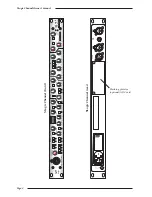
There are four connectors on the rear panel and a single combined XLR and mono jack on the front panel.
The rear panel connections are:
Input A (female XLR)
Output (male XLR)
Key Input (female XLR)
Link Bus (TRS jack socket)
The front panel connections are:
Input B/Instrument (combined female XLR and mono jack)
Inputs A and B are can be used for either microphone or line level signals. The
HI Z
switch should be selected
when using line level signals as some devices may not be able to provide full output level in to the low (1.2kΩ)
impedance of the standard microphone input.
The mono jack provides a very high (1MΩ) impedance input, designed for use with guitar pickups, piezo electric
bugs etc.
Connect the output of the unit to your recorder, workstation or mixing desk. Connect the input to a suitable
source. If you have more than one unit the dynamics LINK jacks on the rear of the units should be connected
together using a mono or stereo jack–to–jack cable.
Installation
Page 7
Summary of Contents for XLogic Super Analogue
Page 1: ...Super Analogue Channel Owner s Manual ...
Page 2: ......
Page 29: ...Notes Appendix Page 25 ...


