Chapter 2: Configuring Your SkyWay Series Unit(s)
26
Configuring ALC/ADFC
The purpose of ALC is to periodically adjust the output power to the target output
power if it has changed due to environmental or configuration changes
(temperature, antenna, user added attenuation.) to ensure that the unit output
power complies with the rules and mandates of the FCC, and other regulatory
bodies.
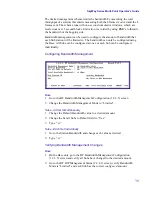
The fields and settings are:
Antenna Detector ADC Value.
This is a reading of the chip code for Solectek
antennas.
Antenna Type.
This is the antenna type based on the channel 1 value.
Maximum Output Power.
This is the maximum output power this unit can
transmit, for the type of antenna it is connected to, under the current country's
laws.
User Added Attenuation.
0-31 dB
(Read/Write). This is the amount of extra
attenuation the user has specified to decrease the transmit output power
Target Output Power.
This is the power in which the ALC will automatically
adjust to. This target is equal to the maximum output power subtracted by the user
added attenuation.
Digital Attenuator Setting.
This is the current amount of dB that the digital
attenuator is adding to the transmit output power signal. Less dB means a higher
output power signal is being sent, more dB means a lower output power is being
sent.
ALC Status.
OFF, Unlocked, Locked, and Locked checking
.
Off
indicates the
port is down and ALC will do nothing.
Unlocked
indicates that the system is
currently adjusting the power to meet the target.
Locked
indicates that the actual
output power and the target output power are equal, and the power is stable.
Locked
checking indicates that the timer has expired, and although it is currently
locked, the ALC will check to ensure that the output power has not changed.
ALC Tx Power Check Timeout.
1 to 30,000 seconds; defaulted to 1800
seconds (30 mins)
(Read-Write). This is the timeout value in seconds that the ALC
will check its transmit output power.
Power Detector ADC Value.
This is the ADC value read from channel 0 which
is the transmit output power level.
Summary of Contents for SkyMate
Page 6: ...About This Manual vi ...
Page 20: ...Chapter 1 Getting to Know Your SkyWay Series 6 ...
Page 100: ...Appendix A RunTime Bios Application Menu Trees 86 ...
Page 102: ...Appendix B SNMP MIB Trap Messages 88 ...
Page 120: ...Appendix C Glossary and Basic Concepts 106 ...
Page 124: ...Index 110 ...


